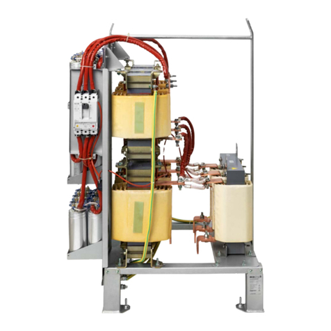
Schaffner Ecosine FN3446 Series Operating manual

1/46 User and installation manual Ecosine Flex Passive Harmonic Filters
Revision: 01 (July 2023)
English version (original instructions)
The most current edition of this document (PDF format) can be obtained from your contact of the
Schaffner organization or at schaffner.com/downloads.
Other technical documentations of our products are also available in the download area of our website
schaffner.com.
Document name:
User and installation manual Ecosine Flex Passive Harmonic Filters rev01.pdf
Valid for Ecosine Flex Passive Harmonic Filters version:
FN3446 series for 380-480 VAC at 50 Hz
FN3458 series for 380-480 VAC at 60 Hz
Version history
Revision
Date
Description
01
July 2023
Initial version

User and installation manual Ecosine Flex Passive Harmonic Filters 2/46
i. Ecosine Flex Passive Harmonic Filters product
highlights
Schaffner Ecosine Flex Passive Harmonic Filters are configurable products which provide an
economical solution for current harmonics mitigation of 3-phase 6 pulse non-linear loads.
The two product lines, FN3446 and FN3458 are applicable for low voltage 50 Hz and 60 Hz systems
respectively and they are particularly suitable for AC and DC motor drives, battery chargers and other
power electronics applications with 6-pulse front-end rectifiers.
Ecosine Flex Passive Harmonic Filters are the most economical harmonic mitigation solution to reach
10% THDi and introduce the following aspects of novelty:
▪Ecosine Flex provides a ready to use solution for the most competitive projects. Ecosine
Flex Passive Harmonic Filters are designed for three-phase diode and thyristor rectifier. It allows
to reach performances below 10% THDi with drives equipped with ≥4% DC-Link choke (Ldc). It
can also be used with drives equipped with a DC-Link choke <4% or without DC-Link choke for
a performance below 15% THDi. The new generation Ecosine Flex Passive Harmonic Filters
targets the requirement of EN 61000-3-12 and IEEE-519 for Isc/IL <50 and other stringent in-
ternational power quality standards.
▪Most compact design, robust, reliable and ready to use.
▪The upgraded version of the Schaffner power quality simulator SchaffnerPQS3
(pqs.schaffner.com) provides the possibility to simulate Ecosine Flex Passive Harmonic Filters
within an electrical system. It furthermore offers quick and accurate performance checks.
This user manual is intended to support designers, installers, and application engineers with filter
selection, installation, application, and maintenance. It provides helpful solutions to overcome harmonics
mitigation challenges and answers frequently asked questions.
If you require additional support, please feel free to contact your local Schaffner representative.
ii. Performance Guarantee
By selecting and installing the appropriate ecosine evo passive harmonic filter in a variable frequency
AC drive application, variable speed drive application within our published technical specifications, we
guarantee that the input current distortion will be less than or equal to 15% THDi for standard Ecosine
Flex series filters at rated power when used with drive not equipped with EMI filter, and 10% THDi for
drives with ≥4% Ldc and no EMI filter. Ecosine Flex filters can also provide similar performance in other
drive applications such as, drive with EMI filter, constant torque, DC drives or other phase-controlled
rectifiers, e.g. SCR drives, but actual THDi levels can vary by load and/or speed and/or firing angle of
thyristors and therefore cannot be guaranteed. Consult your local Schaffner representative for
assistance when applying ecosine filters on these types of equipment.
iii. Minimum system requirements
The guaranteed performance levels of this filter will be achieved when the following system conditions
are met:
▪Type of load: Any 3-phase equipment with front-end six-pulse diode rectifier.
▪Type of source: 3-phase power line without neutral
▪Line impedance: <3% (calculated for the rated filter power)
▪Line frequency: 50 Hz ±1 Hz (FN3446), 60 Hz ±1 Hz (FN3458)
▪Line voltage: Nominal line voltage ±10%
▪Line voltage unbalance: <1%
▪Line voltage distortion: THVD <2%
3/46 User and installation manual Ecosine Flex Passive Harmonic Filters
iv. Important user notice
Schaffner Ecosine Flex Passive Harmonic Filters are designed for the operation on the input (grid) side
of power electronic equipment with six-pulse rectifier front-end in balanced three-phase power systems,
like typically used in AC or DC motor drives and high-power DC supplies. Filter suitability for a given
application must be determined by the user on a case-by-case basis. Schaffner will not assume liability
for any consequential downtimes or damages resulting from use or application of Ecosine filters outside
of their specifications. Ecosine filters are not designed for single-phase or split-phase applications.

User and installation manual Ecosine Flex Passive Harmonic Filters 4/46
v. General Safety Notes and Installation Guidelines
(Cautions and Warnings)

5/46 User and installation manual Ecosine Flex Passive Harmonic Filters
Table of Contents
1Ecosine Flex Passive Harmonic Filters designation.....................7
1.1 Explanation of Ecosine Flex designation...................................................... 7
1.2 Selection of Ecosine Flex filter....................................................................... 7
2Filter selection..................................................................................8
2.1 Filter selection table FN3446 (50 Hz, 3×380 … 480 VAC) ........................... 10
2.2 Filter selection table FN3458 (60 Hz, 3×380 … 480 VAC) ........................... 12
2.3 Filter configurations...................................................................................... 14
3Filter description............................................................................15
3.1 General electrical specifications FN3446 (50 Hz filters)............................. 15
3.2 General electrical specifications FN3458 (60 Hz filters)............................. 16
3.3 Additional electrical specifications.............................................................. 17
3.3.1 Clearance derating by altitude............................................................................................. 17
3.3.2 Current derating by altitude................................................................................................. 17
3.4 Screw size, torque and cable cross-section requirement.......................... 17
3.4.1 Filter terminals..................................................................................................................... 17
3.4.2 Earth terminals .................................................................................................................... 18
3.5 Thermal protection switch specifications ................................................... 18
3.6 Cooling requirement...................................................................................... 19
3.7 Mechanical frame sizes................................................................................. 20
3.8 Ecosine Flex filter footprint and dimensions.............................................. 22
3.9 Filter performance......................................................................................... 28
3.9.1 Additional considerations regarding the performances....................................................... 29
3.10 Functional diagram..................................................................................... 30
4Filter appearance and elements....................................................31
5Performance estimation using SchaffnerPQS.............................32
6Filter application ............................................................................33

User and installation manual Ecosine Flex Passive Harmonic Filters 6/46
7Filter installation ............................................................................34
7.1 Step 1: Visual inspection .............................................................................. 34
7.2 Step 2: Mounting............................................................................................ 34
7.2.1 Fixation................................................................................................................................ 35
7.2.2 Screws and bolts selection.................................................................................................. 35
7.2.3 Filter placement................................................................................................................... 35
7.3 Step 3: Wiring................................................................................................. 36
7.3.1 Verify safe disconnection of all line side power................................................................... 36
7.3.2 Carefully connect protective earth (PE) wire to adequate earth potential close to Ecosine
filter. 36
7.3.3 Connect PE cable of Ecosine filter...................................................................................... 36
7.3.4 Connect Ecosine load side terminals L1’, L2’, L3’ to respective motor drive or rectifier inputs.
37
7.3.5 Use wired trap circuit or install external capacitive current control. .................................... 37
7.3.6 Connect monitor switch TS- TS’.......................................................................................... 37
7.3.7 Connect Ecosine line side terminals L1, L2, L3 to power input protection (current limiting
fuses –see below)............................................................................................................................. 38
7.3.8 Fuses................................................................................................................................... 39
8Filter maintenance .........................................................................41
8.1 Maintenance schedule .................................................................................. 41
8.2 Fan.................................................................................................................. 41
8.3 Power capacitors........................................................................................... 42
8.3.1 Note regarding the storage of capacitors............................................................................ 42
8.4 Electrical connections................................................................................... 42
9Trap circuit disconnect..................................................................43
10 Troubleshooting..........................................................................44
11 Abbreviation ................................................................................44

7/46 User and installation manual Ecosine Flex Passive Harmonic Filters
1 Ecosine Flex Passive Harmonic Filters designation
1.1 Explanation of Ecosine Flex designation
Ecosine Flex is the new generation of Schaffner 10% THDi passive harmonic filter. They are introduced
with a new designation system, which contains of 4 sections connected with ‘-’ as shown in
Figure 1 Ecosine Flex designation
▪The first part of the designation ‘FN34nn-xxx-yy-_ _ _ _ _ _ _’ distinguishes between the two
series, FN3446 for network at 50Hz and FN3458 for network at 60Hz.
▪The second part of the designation ‘FN34nn-xxx-yy-_ _ _ _ _ _ _’ indicates the motor drive
power rating, in kW for 50 Hz filters and in HP for 60 Hz filters. Please note that Ecosine Flex
filters are not using current rating in the designation anymore.
▪The third part of the designation ‘FN34nn-xxx-yy-_ _ _ _ _ _ _’ indicates the power terminal
type. For more information please see section 3.4.1.
▪The fourth part of the designation ‘FN34nn-xxx-yy-_ _ _ _ _ _ _’ contains seven slots, the first
two slots reveal the protection category of the filter, e.g. E0 and E2 represent IP 00 and IP 20
enclosure. The following five slots represent the presence (F,A,R,J,P) or absence (X) of mod-
ules in the filter.
1.2 Selection of Ecosine Flex filter
Ecosine Flex filters are simple to select.
First, define the series according to the network frequency, FN3446 for 50Hz or FN3458 for 60Hz.
Secondly, choose between the IP00 (-E0_ _ _ _ _) or IP20 (-E2_ _ _ _ _) depending on your need.
Note that IP00 versions are not equipped with active cooling and it’s the responsibility of the customer
to ensure the appropriate cooling in the cabinet, see section 3.6 for more details. IP20 version filters are
equipped with fan and the power supply for the fan when a cooling is necessary, no further requirement
regarding cooling and powering of the fan is needed.

User and installation manual Ecosine Flex Passive Harmonic Filters 8/46
2 Filter selection
Ecosine Flex filters are simple to select according to the network frequency and the IP protection degree
needed.
As an additional support from the step below, Schaffner offers the Schaffner Power Quality Simulator
SchaffnerPQS3 (pqs.schaffner.com) to select and verify the most suitable Ecosine filter for your
application.
Step 1: Grid frequency
Determine, whether the system in consideration will be operated in a 50 Hz or 60 Hz electricity grid,
and select the corresponding filter series according to the following table:
50 Hz grid
Europe, Middle East, parts of Asia, parts of South America
FN3446
60 Hz grid
North and Central America, parts of Asia, parts of South America
FN3458
Note: a 50 Hz filter will not provide satisfying harmonics mitigation in a 60 Hz grid, and vice versa.
Step 2: Grid voltage
Verify that the grid configuration is suitable for standard Ecosine Flex Passive Harmonic Filters ac-
cording to the following table:
50 Hz grid
Nominal voltage 380–480 V AC
TN, TT, IT configuration
60 Hz grid
Nominal voltage 380–480 V AC
TN, TT, IT configuration
Step 4: Rectifier/Drive input power
The individual filter must be selected with respect to the rectifier/motor drive input power in kW respec-
tively in HP. It is important to match rated filter power as close as possible with the effective input
power of the rectifier/drive.
Note that if the rectifier/drive is being operated very close to its rated power, then the filter can be se-
lected by the motor drive’s nominal power rating. However, if the drive will be operated e.g. at only
66% of its rated power, then a smaller filter should be selected in order to get maximum harmonics
mitigation performance and the optimum in terms of cost, size, and weight. In that case the customer
is responsible to ensure that Ecosine Flex Passive Harmonic Filters will be operated within specifica-
tion. This is particularly important in terms of overload.
Please refer to the following examples:
Example 1:
Power line rating: 400 V, 50 Hz
Drive rating: 380–500 V, 50–60 Hz, 15 kW, 22.5 A, B6-diode rectifier without DC-link choke
Planned rectifier/drive input real power: 15kW (100% of drive rating)
➔Recommended filter according to the filter selection table FN3446: Type FN3446-15-33

9/46 User and installation manual Ecosine Flex Passive Harmonic Filters
Example 2:
Power line rating: 480 V, 60 Hz
Drive rating: 380–500 V, 50–60 Hz, 30 HP, 41 A, diode rectifier
Planned rectifier/drive input real power: 30 HP (100% of drive rating)
➔Recommended filter according to the filter selection table FN3458: Type FN3458-30-33
Oversizing of passive harmonic filters is not recommended because of the inherent lower harmonic
mitigation performance at partial load as well as higher cost, size, and weight.
Please refer to Table 1 to Table 4 to select suitable filters.

User and installation manual Ecosine Flex Passive Harmonic Filters 10/46
2.1 Filter selection table FN3446 (50 Hz, 3×380 … 480 VAC)
Table 1 FN3446 IP00 filter selection table
Filter
Rated
load
power
@400
V/50 Hz
Rated
load
power
@480
V/50 Hz
Motor
drive in-
put cur-
rent
Rated fil-
ter input
current
Weight
Typical
losses
Input
/output
terminals
TDJ ter-
minals
Frame
size
[kW]
[kW]
[Arms]***
[Arms]
[kg]
[W]****
Type
Type
FN3446-4-44-E0XXJXX
4
4.8
10
5.9
9
75
-44
-44
A
FN3446-6-44-E0XXJXX
5.5
6.6
12.5
8.1
9
129
-44
-44
A
FN3446-8-44-E0XXJXX
7.5
9.0
17.5
11.1
13
129
-44
-44
A
FN3446-11-33-E0XXJXX
11
13
25.1
16.2
16
203
-33
-44
B
FN3446-15-33-E0XXJXX
15
18
33
22.2
18
327
-33
-44
B
FN3446-19-33-E0XXJXX
19
23
42
27.3
21
244
-33
-44
B
FN3446-22-33-E0XXJXX
22
26
50
32.5
26
327
-33
-44
B
FN3446-30-34-E0XXJXX
30
36
67
44.5
34
370
-34
-33
C
FN3446-37-34-E0XXJXX
37
44
81
54.7
40
414
-34
-33
C
FN3446-45-35-E0XXJXX
45
54
99
66.6
43
448
-35
-33
D
FN3446-55-35-E0XXJXX
55
66
120
81.5
52
583
-35
-33
D
FN3446-75-40-E0XXJXX
75
90
160
111
80
618
-40
-34
E
FN3446-90-40-E0XXJXX
90
108
190
132
85
632
-40
-34
E
FN3446-110-40-E0XXJXX
110
132
232
164
92
790
-40
-34
E
FN3446-132-99-E0XXJXX
132
158
271
197
103
711
-99
-35
F
FN3446-160-99-E0XXJXX
160
192
328
236
114
888
-99
-35
F
FN3446-200-99-E0XXJXX
200
240
403
301
124
1105
-99
-40
G
* Filter rating which does not require forced cooling
** Motor drive input current without harmonic filter
*** Typical losses @ 45°C, 400V, 50Hz and rated load power

11/46 User and installation manual Ecosine Flex Passive Harmonic Filters
Table 2 FN3446 IP20 filter selection table
Filter
Rated
load
power
@400
V/50 Hz
Rated
load
power
@480
V/50 Hz
Motor
drive in-
put cur-
rent
Rated fil-
ter input
current
Weight
Typical
losses
Input
/output
terminals
TDJ ter-
minals
Frame
size
[kW]
[kW]
[Arms]***
[Arms]
[kg]
[W]****
Type
Type
FN3446-4-44-E2XXJXX**
4
4.8
10
5.9
10
75
-44
-44
A
FN3446-6-44-E2XXJXX**
5.5
6.6
12.5
8.1
10
129
-44
-44
A
FN3446-8-44-E2XXJXX**
7.5
9.0
17.5
11.1
15
129
-44
-44
A
FN3446-11-33-E2FAJXX
11
13
25.1
16.2
18
203
-33
-44
B
FN3446-15-33-E2FAJXX
15
18
33
22.2
20
327
-33
-44
B
FN3446-19-33-E2FAJXX
19
23
42
27.3
23
244
-33
-44
B
FN3446-22-33-E2FAJXX
22
26
50
32.5
28
327
-33
-44
B
FN3446-30-34-E2FAJXX
30
36
67
44.5
37
370
-34
-33
C
FN3446-37-34-E2FAJXX
37
44
81
54.7
43
414
-34
-33
C
FN3446-45-35-E2FAJXX
45
54
99
66.6
46
448
-35
-33
D
FN3446-55-35-E2FAJXX
55
66
120
81.5
55
583
-35
-33
D
FN3446-75-40-E2FAJXX
75
90
160
111
85
618
-40
-34
E
FN3446-90-40-E2FAJXX
90
108
190
132
91
632
-40
-34
E
FN3446-110-40-E2FAJXX
110
132
232
164
99
790
-40
-34
E
FN3446-132-99-E2FAJXX
132
158
271
197
111
711
-99
-35
F
FN3446-160-99-E2FAJXX
160
192
328
236
122
888
-99
-35
F
FN3446-200-99-E2FAJXX
200
240
403
301
132
1105
-99
-40
G
* Filter rating which does not require forced cooling
** Motor drive input current without harmonic filter
*** Typical losses @ 45°C, 400V, 50Hz and rated load power

User and installation manual Ecosine Flex Passive Harmonic Filters 12/46
2.2 Filter selection table FN3458 (60 Hz, 3×380 … 480 VAC)
Table 3 FN3458 IP00 filter selection table
Filter
Rated
load
power
@400
V/60 Hz
Rated
load
power
@480
V/60 Hz
Motor
drive
input
current
Rated
filter
input
current
Weight
Typical
losses
Terminal
Frame
size
[HP]
[HP]
[Arms]**
[Arms]
[kg]
[W]***
FN3458-5-44-E0XXJXX
5
3.7
5.3
4.6
9
41
-44
B
FN3458-8-44-E0XXJXX
7.5
5.6
7.9
6.9
9
81
-44
B
FN3458-10-44-E0XXJXX
10
7.5
10.6
9.2
13.3
72
-44
B
FN3458-15-33-E0XXJXX
15
11
15.8
13.8
16.2
152
-33
C
FN3458-20-33-E0XXJXX
20
15
21.1
18.5
18.3
214
-33
C
FN3458-25-33-E0XXJXX
25
19
26.3
23.0
20.9
277
-33
C
FN3458-30-33-E0XXJXX
30
22
31.6
27.7
25.6
289
-33
C
FN3458-40-34-E0XXJXX
40
30
42.2
36.9
33.5
383
-34
D
FN3458-50-34-E0XXJXX
50
37
52.7
46.2
40
393
-34
D
FN3458-60-35-E0XXJXX
60
45
64.1
55.9
42.5
493
-35
E
FN3458-75-35-E0XXJXX
75
56
78.7
69.0
45.2
514
-35
E
FN3458-100-40-E0XXJXX
100
75
105
92.2
78
741
-40
F
FN3458-125-40-E0XXJXX
125
93
131
115
83.5
832
-40
F
FN3458-150-40-E0XXJXX
150
112
157
139
91.5
873
-40
F
FN3458-200-99-E0XXJXX
200
149
209
185
101
876
-99
G
FN3458-250-99-E0XXJXX
250
186
261
231
112
984
-99
G
FN3458-300-99-E0XXJXX
300
224
294
280
122
739
-99
G
* Filter rating which does not require forced cooling
** Motor drive input current without harmonic filter
*** Typical losses @ 45°C, 400V, 50Hz and rated load power

13/46 User and installation manual Ecosine Flex Passive Harmonic Filters
Table 4 FN3458 IP20 filter selection table
Filter
Rated load
power
@480 V/60
Hz
Rated load
power
@380 V/60
Hz
Motor
drive in-
put cur-
rent
Rated
filter in-
put cur-
rent
Weight
Typical
losses
Input
/out-
put
termi-
nals
TDJ
ter-
mi-
nals
Frame
size
[kW]
[HP]
[kW]
[HP]
[Arms]***
[Arms]
[kg]
[lbs]
[W]****
Type
Type
FN3458-5-44-E0XXJXX
3.7
5
3
4
6.7
4.6
9
20
60
-44
-44
B
FN3458-8-44-E0XXJXX
5.6
7.5
4.4
5.9
10
6.9
9
20
117
-44
-44
B
FN3458-10-44-E0XXJXX
7.5
10
5.9
7.9
13.4
9.2
13.3
29
99
-44
-44
B
FN3458-15-33-E0XXJXX
11.2
15
8.9
12
20
13.8
16.2
36
174
-33
-44
C
FN3458-20-33-E0XXJXX
14.9
20
11.9
16
27
18.5
18.3
40
253
-33
-44
C
FN3458-25-33-E0XXJXX
19
25
14.9
20
34
23.0
20.9
46
307
-33
-44
C
FN3458-30-33-E0XXJXX
22
30
18
24
41
27.7
25.6
56
380
-33
-44
C
FN3458-40-34-E0XXJXX
30
40
24
32
54
36.9
33.5
74
336
-34
-33
D
FN3458-50-34-E0XXJXX
37
50
30
40
67
46.2
40
88
412
-34
-33
D
FN3458-60-35-E0XXJXX
45
60
36
48
81
55.9
42.5
94
466
-35
-33
E
FN3458-75-35-E0XXJXX
56
75
44
59
99
69.0
45.2
99
490
-35
-33
E
FN3458-100-40-E0XXJXX
75
100
59
79
131
92.2
78
172
634
-40
-34
F
FN3458-125-40-E0XXJXX
93
125
74
99
162
115
83.5
184
805
-40
-34
F
FN3458-150-40-E0XXJXX
112
150
89
119
191
139
91.5
201
615
-40
-34
F
FN3458-200-99-E0XXJXX
149
200
118
158
253
185
101
222
843
-99
-35
G
FN3458-250-99-E0XXJXX
186
250
148
198
311
231
112
246
910
-99
-35
G
FN3458-300-99-E0XXJXX
224
300
177
238
368
280
122
268
1026
-99
-40
G
FN3458-5-44-E2XXJXX**
3.7
5
3
4
6.7
4.6
10
22
60
-44
-44
B
FN3458-8-44-E2XXJXX**
5.6
7.5
4.4
5.9
10
6.9
10
22
117
-44
-44
B
FN3458-10-44-E2XXJXX**
7.5
10
5.9
7.9
13.4
9.2
14.7
32
99
-44
-44
B
FN3458-15-33-E2FAJXX
11.2
15
8.9
12
20
13.8
18
40
174
-33
-44
C
FN3458-20-33-E2FAJXX
14.9
20
11.9
16
27
18.5
19.8
44
253
-33
-44
C
FN3458-25-33-E2FAJXX
19
25
14.9
20
34
23.0
23.4
51
307
-33
-44
C
FN3458-30-33-E2FAJXX
22
30
18
24
41
27.7
28.2
62
380
-33
-44
C
FN3458-40-34-E2FAJXX
30
40
24
32
54
36.9
37
81
336
-34
-33
D
FN3458-50-34-E2FAJXX
37
50
30
40
67
46.2
43
95
412
-34
-33
D
FN3458-60-35-E2FAJXX
45
60
36
48
81
55.9
46
101
466
-35
-33
E
FN3458-75-35-E2FAJXX
56
75
44
59
99
69.0
48.5
107
490
-35
-33
E
FN3458-100-40-E2FAJXX
75
100
59
79
131
92.2
83
183
634
-40
-34
F
FN3458-125-40-E2FAJXX
93
125
74
99
162
115
88.5
195
805
-40
-34
F
FN3458-150-40-E2FAJXX
112
150
89
119
191
139
97.5
215
615
-40
-34
F
FN3458-200-99-E2FAJXX
149
200
118
158
253
185
109
240
843
-99
-35
G
FN3458-250-99-E2FAJXX
186
250
148
198
311
231
120
264
910
-99
-35
G
FN3458-300-99-E2FAJXX
224
300
177
238
368
280
130
286
1026
-99
-40
G
* Filter rating which does not require forced cooling
** Motor drive input current without harmonic filter
*** Typical losses @ 45°C, 400V, 50Hz and rated load power

User and installation manual Ecosine Flex Passive Harmonic Filters 14/46
2.3 Filter configurations
The following block diagrams represent the filter configurations.
FN34nn-xxx-yy-E2FAJXX
FN34nn-xxx-yy-E0XXJXX and
FN34nn-xxx-yy-E2XXJXX

15/46 User and installation manual Ecosine Flex Passive Harmonic Filters
3 Filter description
3.1 General electrical specifications FN3446 (50 Hz filters)
Nominal operating voltage:
3x 380 to 480 V AC
Voltage tolerance range:
3x 342 to 528 V AC
Operating frequency:
50 Hz ±1 Hz
Network:
TN, TT, IT
Nominal motor drive input power rating:
4 to 200kW
Total harmonic current distortion THDi: 1)
< 10% @ rated power with DC-Link choke ≥4%
< 15% @ rated power with DC-Link choke < 4%
Total demand distortion TDD: 1)
According to IEEE 519
Efficiency:
≥98%@ nominal line voltage and power
Drive dc-link voltage:
-5% ~ +10% nominal VDC
High potential test voltage: 2)
P →E 2480 VAC (1s)
SCCR: 3)
100kA, fuses according UL class J or IEC class gG
Protection category:
IP 00, IP 20
Pollution degree:
PD2 (according to standard IEC 60664-1)
Cooling:
Internal fan cooling or external cooling 4)
Overload capability:
1.6x rated current for 1 minute, once per hour
Capacitive current @ no load:
<30% of rated input current, at 400 V AC
Ambient temperature range:
-25°C to +45°C fully operational
+45°C to +70°C derated operation 5)
-25°C to +85°C transportation and storage
Flammability class:
UL 94V-2
Insulation class of magnetic components:
200(N) acc. UL 1446
Design corresponding to:
Filter: UL/IEC 61800-5-1, EN 61800-5-1
Chokes: EN 61558-2-20
MTBF @ 45°C/400 V (Mil-HB-217F):
>300,000 hours
MTTR:
<15 minutes (capacitor modules and fan modules)
Lifetime (calculated):
≥10 years with maintenance
Safety monitor output signal:
Thermal switch NC 180° C (UL-approved) to detect
overload of chokes
1) System requirements: THVD <2%, line voltage unbalance <1%, line impedance <3%
Performance specification for six-pulse diode rectifiers. SCR rectifier front-end produce different results, depending upon
the firing angle of the thyristors.
2) Repetitive tests to be performed at max. 80% of above levels, for 2 seconds.
3) External UL-rated fuses required.
4) Please check the inlet air flow required for cooling in section 3.6.
5) Iderated = Inominal×((70°C-Tamb)/25°C)

User and installation manual Ecosine Flex Passive Harmonic Filters 16/46
3.2 General electrical specifications FN3458 (60 Hz filters)
Nominal operating voltage:
3x 380 to 480 V AC
Voltage tolerance range:
3x 342 to 528 V AC
Operating frequency:
60 Hz ±1 Hz
Network:
TN, TT, IT
Nominal motor drive input power rating:
5 to 300 HP (4 to 224kW)
Total harmonic current distortion THDi: 1)
< 10% @ rated power with DC-Link choke ≥4%
< 15% @ rated power with DC-Link choke < 4%
Total demand distortion TDD: 1)
According to IEEE 519
Efficiency:
≥98%@ nominal line voltage and power
Drive dc-link voltage:
-5% ~ +10% nominal VDC
High potential test voltage: 2)
P →E 2480 VAC (1s)
SCCR: 3)
100kA, fuses according UL class J
Protection category:
IP 00, IP 20
Pollution degree:
PD2 (according to standard IEC 60664-1)
Cooling:
Internal fan cooling or external cooling 4)
Overload capability:
1.6x rated current for 1 minute, once per hour
Capacitive current @ no load:
<30% of rated input current, at 480 V AC
Ambient temperature range:
-25°C to +45°C fully operational
+45°C to +70°C derated operation 5)
-25°C to +85°C transportation and storage
Flammability class:
UL 94V-2
Insulation class of magnetic components:
200(N) acc. UL 1446
Design corresponding to:
Filter: UL/IEC 61800-5-1, EN 61800-5-1
Chokes: EN 61558-2-20
MTBF @ 45°C/400 V (Mil-HB-217F):
>300,000 hours
MTTR:
<15 minutes (capacitor modules and fan modules)
Lifetime (calculated):
≥10 years with maintenance
Safety monitor output signal:
Thermal switch NC 180° C (UL-approved) to detect
overload of chokes
1) System requirements: THVD <2%, line voltage unbalance <1%, line impedance <3%
Performance specification for six-pulse diode rectifiers. SCR rectifier front-end produce different results, depending upon
the firing angle of the thyristors.
2) Repetitive tests to be performed at max. 80% of above levels, for 2 seconds.
3) External UL-rated fuses required.
4) Please check the inlet air flow required for cooling in section 3.6.
5) Iderated = Inominal×((70°C-Tamb)/25°C)

17/46 User and installation manual Ecosine Flex Passive Harmonic Filters
3.3 Additional electrical specifications
Ecosine Flex Passive Harmonic Filters general electrical specifications refer to operating altitudes up to
2000m (6600ft) above sea level.
Operation between 2000m and 4000m (6600ft and 13123ft) requires a derating for clearance and
current.
3.3.1 Clearance derating by altitude
Table 5 Altitude correction factors for clearances (extract from table A.2 in IEC 60664-1)
Altitude [m]
Normal barometric pressure
Multiplication factor for
clearances
[m]
[kPa]
2’000
80.0
1.00
3’000
70.0
1.14
4’000
62.0
1.29
3.3.2 Current derating by altitude
The current derating is the factor to which the nominal current needs to be multiplied. A simplified
equation can be defined as function of ΔH (H –2000). This equation is valid for H up to 4000 meters
(ΔH = 2000 m).
Example: at an altitude of 3’500m, we get ΔH = 1’500m and the current derating = 0.9187. A filter with
a rated current of 100A can only be used up to 91.87A.
Remark: Do not use Ecosine Flex Passive Harmonic Filters in altitudes above 4000m.
3.4 Screw size, torque and cable cross-section requirement
3.4.1 Filter terminals
Several types of terminals are used in Ecosine Flex filters for both the power (input/output) terminals
and the TDJ terminals but their types are not necessary the same for each filter size (e.g. FN3446-11-
33 has power terminals type -33 and TDJ terminals type -44).
The terminals connecting the temperature switch (see section 3.5) is the same for all filters, type TS.
The cable cross-section must be selected according to the rated filter input current or trap current for
TDJ, the maximum current, the environment and other special requirements of the application. It should
be stranded copper wire cable with a temperature rating of ≥75°C.
The power terminals type is given by the filter designation, in the third section, see section 1.1 and in
the filter selection table, see section 2.1 and 2.2 or the datasheet.
The TDJ terminals type is given in the filter selection table, see section 2.1 and 2.2 or the datasheet.
Recommended cable cross-section for each terminal type is given in Table 6. The customer is fully
responsible to define the most appropriate conductor type according to the application and ensure a
proper connection of the filter.

User and installation manual Ecosine Flex Passive Harmonic Filters 18/46
Table 6 Ecosine Flex filter terminals designation
Terminal
designation
LxWxH [mm]
Stranded
wire AWG
Stranded
wire [mm²]
Solid wire
[mm²]
Rec. Torque
[Nm]
Ring cable
shoe
-44
21.9x10x28
20 - 8
0.5 - 6
0.5 - 10
1.0 - 1.2
-
-33
25x11x32
20 - 6
0.5 - 10
0.5 - 16
1.5 - 1.8
-
-34
39x18.5x50.5
10 - 2
6 - 25
6 - 35
4.0 - 4.5
-
-35
45x20x55.5
6 - 1/0
16 - 50
10 - 50
7.0 - 8.0
-
-40
51x25x72.5
1/0 - 4/0
50 -95
50 - 95
17 - 20
-
-99
79x6x25
-
-
-
-
M10
TS
20.5x10x10.9
24 - 10
0.5 - 4
0.5 - 6
0.7 - 0.8
-
3.4.2 Earth terminals
The earth terminals screw size and torque are given in Table 7.
Table 7 Ecosine Flex filter signal and earth terminals
Frame size
Bolt size
Torque [Nm]
A
M6
4.0
B, C
M8
9.0
D, E, F, G
M10
17
3.5 Thermal protection switch specifications
One choke of each type is equipped with a thermal protection switch (temperature switch). The 2
switches are connected in series to the auxiliary terminal TS-TS’. If the temperature switch reaches
the nominal switching temperature (NST), the switch will open.
Table 8 thermal protection switch specifications
Contact type
Normally closed (NC)
Nominal switching temperature (NST)
180°C
Resetting temperature (RST)
145°C (indication only)
Operating voltage
Up to 250V AC
Rated current AC Inom
2.5A cosϕ= 1.0
1.6A cosϕ= 0.6
1.8A cosϕ= 0.4-0.5

19/46 User and installation manual Ecosine Flex Passive Harmonic Filters
3.6 Cooling requirement
Inlet air flow requirements for each frame size are listed in Table 9. Please note that the filters with frame
size A do not require air cooling. For frame sizes B to G, the required inlet air flow must be fulfilled, either
by including the optional fan module or by providing sufficient external air flow.
Table 9 Air flow required for cooling
Frame size
[m3/h]
Min air volume*
CFM [ft3/min]
A
0
0
B, C, D
204
120
E
408
240
F, G
612
360
Remark: External air flow required for filter configurations without embedded
Ventilation.
Important: The required inlet air flow must be provided to guarantee
normal operation of the filter. Insufficient inlet air flow or blocking
of air channel might cause overheating of filter components.
This manual suits for next models
1
Table of contents
Other Schaffner Water Filtration System manuals

Schaffner
Schaffner Ecosine FN34 Series User manual

Schaffner
Schaffner Ecosine max FN 3470 Operating manual

Schaffner
Schaffner ECOsine active FN3420-030-3 Series User manual

Schaffner
Schaffner FN5420 Operating manual

Schaffner
Schaffner ECOsine evo FN 3440 Operating manual

Schaffner
Schaffner FN6840-25-113-E0XXR Operating manual

Schaffner
Schaffner FN 5060 Series Instruction sheet

Schaffner
Schaffner Ecosine FS42842 Series Operating manual

Schaffner
Schaffner FN5420 Operating manual

Schaffner
Schaffner Ecosine evo FN3440 Operating manual