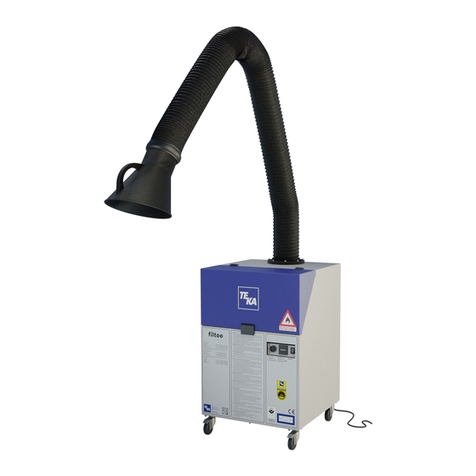
Teka Airfilter MINI User manual

Operating instructions
Airfilter MINI
TEKA Absaug- und Entsorgungs-
technologie GmbH
Industriestraße 13 D-46342 Velen
Postfach 1137 D-46334 Velen
Tel.: +49 (0) 2863 9282-0
Fax: +49 (0) 2863 9282-72
E-Mail: sales@teka.eu
www.teka.eu

BA_Airfilter Mini_151210_GB.doc - 2 - 10.12 2015
Please enter here the specific data relating to the Airfilter you
have purchased, so that if you contact TEKA GmbH by tele-
phone you will have the necessary data immediately on hand:
Description and type of the ap-
pliance:
Airfilter
Year of construction:
Machine no.:
Commission no.:
AU-
Date of commissioning:

Contents
1
Introduction .........................................................................................................4
2
Intended use........................................................................................................5
2.1 Intended use ...................................................................................................................5
3
Safety instructions..............................................................................................6
4
Product description ............................................................................................7
4.1 Overview ......................................................................................................................... 7
4.2 Function description ........................................................................................................ 8
4.3 Connection to the external control................................................................................... 8
4.4 Technical data.................................................................................................................8
5
Transport and Setting up .................................................................................10
6
Commissioning .................................................................................................11
6.1 Commissioning of the Airfilter........................................................................................ 11
6.1.1
Assembly of the suction arm ........................................................................................ 11
6.1.2
Connection of an external control ................................................................................ 12
6.1.3
Connection of the Airfilter ............................................................................................. 13
6.2 Qualification of the operating personnel ........................................................................ 14
6.3 Operation ...................................................................................................................... 14
7
Maintenance ......................................................................................................15
7.1 General information....................................................................................................... 15
7.2 Replacement of the combifilter ...................................................................................... 15
8
Fault and error search ......................................................................................20
9
Disposal .............................................................................................................22
10
Spare parts and parts subject to wear and tear .............................................23
11
Declaration of conformity TEKA-Airfilter ......................................................24
Instruction record for Airfilter MINI........................................................................25

BA_Airfilter Mini_151210_GB.doc - 4 - 22.07.2013
1 Introduction
In recent years, a special type of welding fume extraction systems has become an ever
more prominent factor: Filtering of welding fumes and return of the filtered air into the
workshop area.
This shows that the issue of environmental consideration has turned for the better for all
concerned. There never has been any doubt about the existence of harmful fumes at
welding sites. However, type of fumes depends on the particular welding process and
welding technique. One can generally differentiate between gases and fumes. The
fumes could also be referred to as fine dust. Investigating them under the microscope,
we are able to see particles of a size that will pass through the respiratory tract deep into
our lungs. The size of these particles is a small as 0.001 mm or even less.
Ventilation is the general approach to improve the conditions at the relevant work posi-
tions. Generally, this is effected by continuously exchanging the air in the workshop, i.e.
the total air volume is exchanged at a high rate. This method will reduce the concentra-
tion of harmful particles within the hall to a great extent, however, it will improve the air
within the breathing range of the individual welder to a negligible portion only.
This also applies to overhead suction systems, i.e. the installation of large extraction
hoods overhead of welding places. Here again the heavily polluted air passes upwards
through the breathing range of the welder. Extraction and/or filtering take place overhead
and outside the range of the welder. A point-attack extraction of the welding fumes right
at their place of origin is far more effective than room ventilation or overhead extraction.
Both capital investment for on-the-spot fume extraction as well as the operating costs for
such systems are far below those of the previous conventional solutions.
Environmental and work protection measures are prerequisite for the successful applica-
tion of advanced welding technologies, aside from the optimisation of such welding pro-
cesses. In view of increased awareness of the problems involved and in compliance with
pertinent legal directives, the danger potential for personnel and environment must be
considered at an early stage and it must be minimised using appropriate technical solu-
tions.

BA_Airfilter Mini_151210_GB.doc - 5 - 22.07.2013
2 Intended use
2.1 Intended use
The Airfilters MINI are exclusively for the purpose of suction of gases and fumes, which are
contaminated with harmful substances and which occur in the following areas of activity:
–
Soldering in the electronics industry,
–
Laser processing,
–
Dental and medical technology,
–
Dermatology,
–
Catering and
–
Hairdressers.
An improper use of the device and of live components can cause damag-
es of single elements up to dangers to life and limb!
The unit must not be used to extract welding fumes containing oil, explosive
dusts and gases, hybrid mixes, burning or glowing substances, gases, water
etc. Furthermore, the unit must not be used in explosive zones (If in doubt,
contact the manufacturer!).

BA_Airfilter Mini_151210_GB.doc - 6 - 22.07.2013
3 Safety instructions
The following basic safety measures must be observed to prevent of electric shocks, injury or fire
when using electrical devices:
•Read and follow the instructions listed below before using the filter systems !
•Store the operating and service instructions in a secure and readily accessible space !
•Protect the connecting lead from heat, wetness, oils and sharp edges !
•Confirm the correct voltage. (Refer to the unit type plate)
•Use only original TEKA spare parts !
•Do not operate the unit without a filter cartridge installed !
•Pull the mains plug before opening the unit !
•The exhaust gird must not be obstructed or blocked in any way!
•Always take care that the unit stands secured and that the caster brakes are set !
•Pull the mains plug when cleaning or servicing the unit, when exchanging any parts or
when changing machine settings for a different function !
•The filter cartridges cannot be regenerated for repeated use !
•The filter cartridges must be disposed of according to pertinent legislation and direc-
tives !
•At regular intervals inspect the mains supply lead for signs of damage !
•The unit must not be used when there is any damage or irregularity at the mains supply
lead !
•Use only dry and oil-free compressed air with pressure ratings from minimum 3 bar to 4 bar
maximum.
•Reposition the suction arm during welding operations, if possible by exploiting the thermal
flow of the welding fumes
•The maximum permissible distance of 25 cm to the welding point should not be exceeded.
•Do not use the filter unit when any one or more components of the system are defective,
missing or damaged. In any one of these instances contact the TEKA Service De-
partment: Phone: ++49 (0) 2863 / 92 82 0
•When extracting carcinogenic welding fumes as from the processing of nickel or chrome al-
loys, the requirements of the directives on clean air of the German TRGS 560 ‘Return of
process air when working with carcinogenic media’ must be observed. (And/or the
equivalent national directives for the respective user.) The suction unit TEKA-
STRONGMASTER-BGIA2110/4110 has been checked and approved by the Institute for
Work Safety (BGIA) under the certification number xxxxxx. This certification is part of the
operating instructions.
•Further information regarding the TRGS 560 can be obtained from the
‘BGIA - Berufsgenossenschaftliches Institut für Arbeitssicherheit’
(Institute for work safety of the employers’ liability insurances) at
D-53754 Sankt Augustin, Germany.

BA_Airfilter Mini_151210_GB.doc - 7 - 22.07.2013
4 Product description
4.1 Overview
Figure 1: Total view Airfilter MINI
1 Transparent display, membrane 2 Combifilter
keyboard
3 Pre-filter mat 4 Service flap on the filter housing
5 Castors (partly with brakes) 6 ON/OFF switch, appliance inlet
7 Sub-D-9 plug connection 8 Mains cable
9 Blind plug(various sizes) 10 Blind cover (with 4 screws)
11 Sound absorption module 12 Turbine housing
13 Housing cover 14 Filter housing

BA_Airfilter Mini_151210_GB.doc - 8 - 22.07.2013
4.2 Function description
The Airfilter is used for extracting gases and fumes contaminated with harmful substances.
Either using a suction arm (accessory) extracted directly from the environment of the Airfilter
or a suction hose is directly closed between the machine to be extracted and the Airfilter.
The Airfilter is either switched on or controlled on the membrane keyboard or by the control of
the machine to be extracted (remote switch automatic mechanism).
The gases/fumes extracted by the suction hose/suction arm are extracted into the filter hous-
ing with the used combifilter.
The combifilter consists of the following three filter levels:
–
Pre-filter mat,
–
Air filter and
–
Activated carbon filter with filter end stage.
The clean gas is extracted by turbine below the activated charcoal filter and then emitted to
the atmosphere through the sound absorption module attached at the side.
The Airfilter is connected to the mains supply using a appliance inlet (included). The appli-
ance inlet for the power supply of the Airfilter is positioned on the turbine housing near the
sound absorption module.
4.3 Connection to the external control
A control cable with a sub D9 connection is required for operating the Airfilter via a remote
switch automatic mechanism. The pin terminal assignment of the sub-D9 connection (see in
section 4.5.2) is to be complied with!
4.4 Technical data
Manufacturer:
TEKA GmbH
Industriestrasse 13
D - 46342 Velen
Tel.: ++49 (0) 28 63-92 82-0
Fax: ++49 (0) 28 63-92 82-72
e-Mail: service@ teka.eu
Product designations:
Airfilter MINI
Housing MINI:
Width 365 mm
Height 626 mm
Depth 376 mm
Housing material Sheet steel, lacquered

BA_Airfilter Mini_151210_GB.doc - 9 - 22.07.2013
Atmosphere:
Atmospheric temperature, perm. + 5 °C to + 35 °C
Relative humidity max. 65 %
Data of Airfilter MINI:
Suction output, free blowing 10 - 300 m
3
/h
Connect load 1.2 kW
Power connection 230 V / 50/60 Hz
Max. underpressure 900 - 21.000 Pa
Total weight 28 kg
Sound pressure level 58 dB(A)
Combifilter for Airfilter MINI:
Net weight 4.3 kg
Filter class H 13 (main filter)
and F 7 (Filter end stage)
Filter surface 2.5 m
2
(main filter)
0.5 m
2
(filter end stage)
Pre-filter mat for Airfilter MINI:
Filter class G 4
Filter surface 0.07 m
2

BA_Airfilter Mini_151210_GB.doc - 10 - 22.07.2013
5 Transport and Setting up
•During transport and interim storage, the device has to be protected against weather condi-
tions.
•During transport, the device must be prevented from falling over and shifting.
•Lift and transport the device with the help of a manual lift truck or a forklift.
•When lifting or dropping the device, do not remain under or next to the charge.
•Observe the indications by the manufacturer or contact the manufacturer.
•Only qualified staff is authorized to set up and install the device.
•Wear safety boots equipped with steel toes
•The ground must be free from vibrations.
•If you have doubts, please contact the manufacturer

BA_Airfilter Mini_151210_GB.doc - 11 - 22.07.2013
6 Commissioning
6.1 Commissioning of the Airfilter
6.1.1 Assembly of the suction arm
Note!
Follow the assembly and operating instructions of the respective suction arm!
You will only find general information for this in these operating instructions.
The parts described here are not included in the scope of delivery of the Airfilter.
The suction arm can be assembled on the housing cover of the Airfilter (see the follow-
ing figure).
The suction arm may be assembled in different ways depending on the design.
1 Suction arm, nominal diameter 75 mm
2 Adapter plate NW75/50
3 Suction arm, nominal diameter 50 mm
4 Suction hose
Figure 2: Assembly of various suction arm types on the Airfilter MINI

BA_Airfilter Mini_151210_GB.doc - 12 - 22.07.2013
6.1.2 Connection of an external control
The Airfilter is switched on or controlled (remote switch automatic mechanism) either on the
membrane keyboard or by an external control (e.g. of the machine to be extracted).
The remote switch automatic mechanism is connected to the Airfilter using a nine-pole cable
with sub-D9 plugs.
Figure Pin Designation Explanation
Connector socket
Sub-D9,
on the side of the unit
1 Start contact
In order to put the LMD into operation a contact
between Pin1 and Pin2 have to be established.
Important: LMD switches off first when the time
programmed has been reached. (Overtravel
time approx. 20 s).
2 EXTIN+ Internal switch contact for starting the turbine
and increasing or reducing the motor speed of
the turbine.
3, 4 „Filter alarm“
Floating output (normal open contact) for
interpretation of the warn alarm „Filter alarm“
5, 6 Operation
control
Floating output (normal open contact) for
interpretation of the operation control.
The alarm at this output always occurs when
the unit identifies an operation.
7 Increasing
turbine
motor speed
In order to increase the performance of the
turbine, a contact between Pin7 and Pin2 is
necessary. When spreading a permanent
contact, this motor speed of the turbine will be
increased till the motor speed maximum.
8 Reducing
turbine
motor speed
In order to reduce the performance of the
turbine, a contact between Pin8 and Pin2 is
necessary. When spreading a permanent
contact, this motor speed of the turbine will be
reduced till the motor speed minimum.
9 GND Internal reference potential (Ground)
Table 1: Connection of an external control (arrangement of the plug contact/ terminal assignment of
connection)

BA_Airfilter Mini_151210_GB.doc - 13 - 22.07.2013
6.1.3 Connection of the Airfilter
1 Mains cable
2 Appliance inlet / On/off
3 Connection cable for remote control
(not included)
4 Sub-D9-connection
5 Suction arm (not included)
6 Suction hose (not included)
Figure 3: Connection of the Airfilter
Connect the Airfilter as follows:
●
First you plug the mains cable (Pos. 1) into the appliance inlet (2) on the Airfilter and only
after this the plug of the mains cable into the 230-V socket.
●
Insofar as an external control of the Airfilter is planned, then connect the external control
with the sub-D9 connection (4) to the housing of the turbine using a corresponding cable
(3).
●
Insofar as it is desired, mount the suction arm (5) onto the top of the Airfilter according to
the assembly instructions.
●
Push the air intake fitting of the suction hose (6) into the matching intake opening.
Insofar as the suction output of the Airfilter allows this, several suction hoses may also be
connected, in order e. g. to extract several machines at the same time.
●
Finally check all connections again that they are correct and fitted tightly.
After connecting all hose pipes and checking the connection the Airfilter can be put into oper-
ation.

BA_Airfilter Mini_151210_GB.doc - 14 - 22.07.2013
6.2 Qualification of the operating personnel
Only trained or instructed personnel should be permitted to work at the Airfilter. The respon-
sibilities of the personnel for the installation and maintenance should be clearly defined!
For the instructions we recommended the use of the added instruction record on the last
page of this manual.
Changes to settings on the Airfilter may only be carried out by specially trained service per-
sonnel of TEKA GmbH.
6.3 Operation
Attention:
Possibilities of adjustment of the programme, menu navigation ecc of the system you
will find in the separate attached manual of steering.

BA_Airfilter Mini_151210_GB.doc - 15 - 22.07.2013
7 Maintenance
7.1 General information
All service work must be carried out within the given deadlines and with the corresponding
care.
The life and production quality of the Airfilter can be maintained through precautionary service
of the components.
Besides the regular cleaning you are urgently advised to replace parts subject to wear and
tear as a precautionary measure.
7.2 Replacement of the combifilter
The filter elements are to be replaced, as soon as the measured pressure differential on the
combifilter exceeds the set end value. The display of the pressure differential in the transpar-
ent display shows in this case 100 % and the red error LED (Error) will light permanently.
Some Airfilter models have also been equipped with an acoustic signal (acoustic alarm), that
gives a clear beep sound to report that the filter needs to be replaced.
Note!
The acoustic signal installed in several Airfilter models can be switched off by pressing one of
the buttons +, – or ENTER on the membrane keyboard once.
The acoustic alarm will sound once again every time the Airfilter is switched on.
So that you are regularly reminded that the combifilter needs to be replaced in permanent
operation of the Airfilter, the acoustic signal will be repeated after 8 hours, then after 4 hours,
after 2 hours and then each further hour.
The alarm will cease to sound immediately only after the combifilter has been replaced.
Caution!
Poisonous dust!
When working with /on the filter elements there is the danger that you may breath in raised
dust or come into contact with such.
●
Therefore, before commencement of the work you should put on a fine dust mask of the
protective level 3 and disposal gloves made of polyethylene (long design).
You should proceed as follows when replacing the filter:

BA_Airfilter Mini_151210_GB.doc - 16 - 22.07.2013
Switch off Airfilter
●
Switch off the Airfilter via the membrane keyboard using the button .
Alternatively you can switch off the machine to be extracted. This way the Airfilter will be
switched off automatically after the set post running time.
●
Secure the Airfilter against being switched on again unexpectedly, by:
– first switching the on/off switch to 0and subsequently
– removing the mains cable from the mains socket.
Remove service flap
1 Service flap
Filter housing
2 Filter housing
3 Latch
Figure 4: Remove service flap
●
Hold the service flap (Pos. 1) in both hands and remove it from the
filter housing (2).
Note: You have to pass the resistance of the latch (3)!

BA_Airfilter Mini_151210_GB.doc - 17 - 22.07.2013
Remove combifilter
4 Handle
5 Combifilter
Figure 5: Remove combifilter
●
Hold the handle (4) of the combifilter (5) with one hand and pull the combifilter out of the
filter housing.
Use the other hand to support the combifilter.
●
Place the whole combifilter with the pre-filter mat on top of it into a plastic bag, which can
be seal tightly, and seal it.
●
Dispose of the disassembled combifilter immediately.
Note!
Depending on the consistency of the gases/of the fumes – to be extracted in particular with a
high proportion of dust or fibres – it can be useful, to first check just the pre-filter mat for con-
tamination and if necessary to just replace this.

BA_Airfilter Mini_151210_GB.doc - 18 - 22.07.2013
Insert new combifilter
In principle, the new combifilter will be inserted in the reverse order. Please observe the fol-
lowing work steps:
Figure 6: Insert new combifilter
●
Remove the combifilter, which is to be inserted, with the already integrated pre-filter mat
from the packaging.
●
Push the combifilter into the filter housing.
Make sure that the surrounding gasket on the combifilter is pointing downwards and the
combifilter is pushed in as far as the latch, otherwise the service flap can not be closed.

BA_Airfilter Mini_151210_GB.doc - 19 - 22.07.2013
Close the housing of the Airfilter
6 Service flap
7 Latch
Figure 7: Close filter housing
●
Hold the service flap (6) in both hands and press it evenly onto the service opening, until
the latch (7) engages in the service flap.

BA_Airfilter Mini_151210_GB.doc - 20 - 22.07.2013
8 Fault and error search
Fault Cause Correction
No suction output
(fumes/gases are not
being extracted).
Air intake hose not connected to
the Airfilter.
Connect air intake hose to the
Airfilter.
Air intake hose not connected to
the machine.
Connect air intake hose to the
industrial laser.
Damage to the air intake hose. Replace air intake hose.
Air intake hose is connected to the
wrong machine.
Connect air intake hose to the
correct machine.
Air intake hose is connected to the
wrong point of entry (opening) of
the machine.
Connect air intake hose to the
right point of entry (opening) of
the machine.
Air intake channel blocked. Check air intake channel, if
necessary correct error found.
Clean gas channel blocked. Check clean gas channel, if
necessary correct error found.
Suction output too low
(fumes/gases are hard-
ly being extracted).
Filter package full. Replace filter package, dis-
pose of old filter properly!
Damage to the air intake hose. Replace air intake hose.
Air intake hose not correctly
connected to the Airfilter.
Check fitting of the air intake
hose to the Airfilter, if applica-
ble reinsert into air intake
opening.
Air intake hose not correctly
connected to the machine.
Check fitting of the air intake
hose to the machine if neces-
sary reconnect.
Clean gas channel too narrow. Check clean gas channel, if
necessary correct error found.
Air intake hose is connected to the
wrong point of entry (opening) on
the machine.
Connect air intake hose to the
right point of entry (opening)
on the machine.
Air intake channel too narrow. Check air intake channel, if
necessary correct error found.
Error on the Airfilter. Contact TEKA GmbH, if nec-
essary return Airfilter.
Airfilter is not running. Plug connection power supply not
or wrongly plugged in.
Check/correctly plug in plug
connection power supply.
No power on the socket. Check mains, if necessary cor-
rect error.
Connection cable for external
control not or wrongly plugged in.
Check connection cable for ex-
ternal control, if necessary
plug in correctly.
Table of contents
Other Teka Water Filtration System manuals
Popular Water Filtration System manuals by other brands

purway Crystal Group
purway Crystal Group PUR Quick 6 UF installation manual

Filters itm
Filters itm SEMI AUTO FL user manual

ESK
ESK BOS2-CDM Series Installation and operating instructions

Delta Water Engineering
Delta Water Engineering PFS-M Installation & operating guide

EHEIM
EHEIM Aquaball 2208 manual

AlkaWay
AlkaWay UltraStream user manual

Velcon
Velcon VF-71E installation instructions

AquaSure
AquaSure FORTITUDE PRO Series owner's manual

Donaldson
Donaldson BOFA FireBOX GA user manual

Donaldson
Donaldson AFS-BH430-IBF-ICA instructions

Excalibur Water Systems
Excalibur Water Systems Filtermax EWS POUPCS075 Installation and user guide

Donaldson
Donaldson Ultra-Filter DF 0035 Operation manual