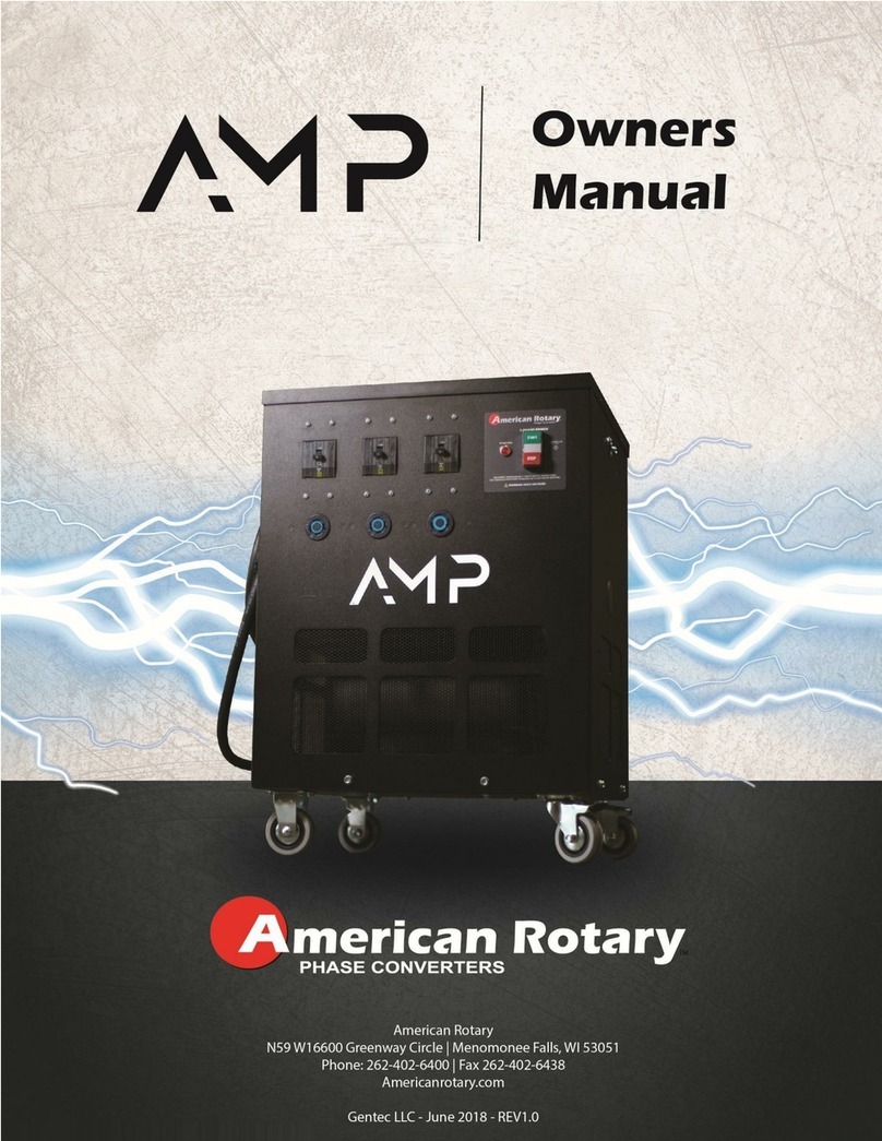
American Rotary 240 VOLT SERIES User manual

ADX-CUL
CNC/HEAVY DUTY
Rotary Phase Converters
240 & 480 VOLT SERIES
SMART SERIES
Operation & Installation Manual
© GENTEC LLC. June 2018 –Rev 1.2

1
TABLE OF CONTENTS
-Warning before starting ….…………………………………………………….2
-Overview ..………………………………………………………………………3
-Warranty .……………………………………………………………………….4
-Return Policy .……………………………………………………………….5
1. Introduction .……………………………………………………………………….6
2. Installation ………………………………………………………………………..7
2.1.Physical Installation ..…………………………………………….………....7
2.1.1. Physical Installation Environmental Considerations .….……7
2.1.2. Installation Guidelines ...……………………………………...……...7
2.1.3. General Wiring Considerations …...…………………....……..9
2.1.4. Wire Sizing Recommendation ....………….…………..……10
3. Operation & Maintenance ..………………………………………………..…...11
3.1. Starting / Stopping ....………………………………...........................11
3.2. Checking Voltages ......………………………………..........................11
3.3. General Maintenance …..………………………………….......................12
3.3.1. Maintenance …...…………………………….............................12
3.3.2. Lubrication .………………………………...............................12
4. Trouble Shooting …......…………………………….....................................13

2
WARNING! READ BEFORE STARTING CONVERTER!
If this phase converter does not start in less than 2 seconds, TURN IT OFF!
1. Make sure the wire size meets our minimum recommended size.
2. All loads INCLUDING TRANSFORMERS must be DISCONNECTED before starting the phase converter
each time. This includes small control transformers that run controls inside your equipment. If you need an
economical 3-phase disconnect switch, please visit www.AmericanRotary.com or call 1-888-743-6832
for assistance.
If your converter still takes more than 2 seconds to start, call our Toll-Free Technical support line 1-888-743-
6832. You will be asked to verify conditions 1 and 2 above are met. Failing to meet these two conditions
account for 99% of starting problems and can result in damage to the starting capacitors.
This converter is quiet. If it does not sound quiet and smooth, TURN IT OFF!
3. Make sure the idler motor is mounted on rubber. DO NOT BOLT THE IDLER MOTOR DOWN! This can
cause bearing failure.
4. Make sure the idler motor is wired properly.
For the American Rotary/Baldor soft-start idler motor
240 Volts Input (1, 7, A), (2, 8, B), (3, 9, C), (4, 5, 6 bolted together and insulated).
480 Volts Input (1, A), (2, B), (3, C). The following bolted together and insulated: (4, 7), (5, 8), (6, 9)
Do not ground any of these connections! Use the supplied bolts and make sure all connections
are insulated. Do not use wire nuts. See pages 8-9 for more in depth instructions.
Failure to wire the idler motor properly will void warranty!
* Make sure the Phase Converter Panel, the Idler Motor, and your equipment is grounded!
5. This phase converter does NOT disconnect the single phase power as it passes through the unit, so the
single phase legs remain energized even when the rotary phase converter is off. In addition to installing a
single phase breaker in front of the phase converter, you need to be aware that the single phase power
DOES flow through the phase converter whether the unit is on or off.
6. Before connecting load, verify proper function of phase converter. This will ensure the protection of the
phase converter and your equipment.
For a stock three-phase motor that uses our Stock Motor Panel, wire
the motor according to the diagram for that motor, NOT according to our wiring diagram.
DANGER: HIGH VOLTAGE
Electric shock could result in death or injury. Please
consult qualified personnel for installation.
DANGER: Risk of Electric Shock
Please wait 30 minutes before servicing
This manual is to serve the purpose of providing recommendations for proper performance
but is not to supersede or replace local or national electric codes. Installation should be done
by a licensed electrician who is familiar with phase converter installations.

3
OVERVIEW
Congratulations on your purchase of a state of the art American Rotary rotary phase
converter. American Rotary along with Baldor Electric have created the ultimate Idler /
Generator to provide balanced voltage and a voltage boost for extra starting torque. The idler
is the phase converter motor which has no shaft and comes as part of the unit. Our super
quiet idler reduces its in-rush starting current by about 75%. The American Rotary / Baldor
Idler is the ultimate in flexibility and smooth true sine-wave power.
All American Rotary rotary phase converters provide the voltage balance and true sinusoidal
3-phase AC output that many of today’s modern machines require. Our control panel has
been engineered to exceed UL, CSA, & NEMA standards. We offer the easiest installation in
the industry with straight line runs, terminal block connections, built-in starter, power guard
restart protection, and no stress capacitor mountings. Rotary phase converters can be
operated from almost any single phase 240/480 VAC power source that has adequate current
carrying capacity. They can operate any type of equipment that requires 3-phase 240/480
VAC.
KEY FEATURES AND CONSIDERATIONS
•Current limiting soft starting idler / generator made exclusively by Baldor
•Built-in starter with power guard restart protection
•Virtually zero harmonic content
•Industrial Control Circuit - the single phase power remains on even when the rotary
phase converter is in the off position, allowing you to activate any single phase control
circuits, DRO’s or other single phase features on your three phase equipment
•Balanced voltages for voltage sensitive equipment
•Convenient terminal blocks for easy connections
•Separate control panel and Idler / generator for optimum space saving installation
•Built in power factor correction
•Loads can be located a large distance from the converter.
•American Rotary rotary phase converters should be wired by an experienced and
qualified electrician into a single phase circuit with proper breaker protection.
•American Rotary rotary phase converters can run any type of load, resistive, inductive,
multiple motor, and in any combination and or number.
•Best warranty in the industry

4
American Rotary Advantage
ADX Panels Only
All American Rotary AD & ADX rotary phase converter control panels are warranted against defects in
material and workmanship for a lifetime. The American Rotary Baldor Idler / Generator is covered by Baldor’s
2 year warranty. The rotor is warranted for lifetime against defects in material and workmanship to the original
owner. Warranty is from the date of purchase by the original owner. American Rotary will repair or replace
(at our option), at no charge, any part(s) found to be faulty during the warranty period specified. The control
panel warranty repairs must be performed by/at American Rotary’s facility. Baldor Idler repairs or
replacements must be performed by/at American Rotary’s facility, or at a Baldor Authorized Service Center.
Baldor Idler repairs or replacements must also be pre-authorized in writing by American Rotary.
Obligations of the Original Owner
1. The original Bill of Sale must be present in order to obtain “in-warranty” service
2. Transportation of control panels to American Rotary is the responsibility of the original purchaser.
Return transportation is provided by American Rotary when the control panel is “in-warranty”
3. American Rotary will not accept Baldor Idler returns or repairs sent to American Rotary. All Baldor
issues are handled by Baldor Authorized Service Centers.
Exclusions of the Warranty
This warranty does not cover any of the following: accident, misuse, fire, flood, and other acts of God, acts of
terrorism, nor any contingencies beyond the control of American Rotary, including water damage, incorrect
line voltage, improper installation, installation where this unit will not meet local electrical codes, missing or
altered serial numbers, and service performed by an unauthorized facility. American Rotary’s’ liability for any
damages caused in association with the use of American Rotary’s’ equipment shall be limited to the repair or
replacement only of the American Rotary’s’ equipment. No person, agent, distributor, dealer, or company is
authorized to modify, alter, or change the design of this merchandise without express written approval of
American Rotary.
Liability Limitation: In no event shall American Rotary be liable or responsible for consequential, incidental or
special damages resulting from or related in any manner to any American Rotary product, third party
installation(s), manufactured or distributed, or parts thereof. A licensed electrician must perform all
installations. Not all American Rotary phase converters are UL listed, this is an option the customer must
specify and additional charges will apply. American Rotary is not responsible for meeting, complying with or
insuring installation inspections. American Rotary does not accept returns on units that have been installed or
energized.
INSTALLATIONS MUST COMPLY WITH ALL NATIONAL AND LOCAL ELECTRICAL CODE REQUIREMENTS AND
MUST BE INSTALLED BY A QUALIFIED LICENSED ELECTRICIAN. CUSTOMER IS RESPONSIBLE FOR MAKING
SURE THIS PHASE CONVERTER CAN PASS INSPECTION WHERE INSTALLED.

5
PRODUCT RETURN POLICY
This policy covers the return of GENTEC/American Rotary products (excluding Warranty
returns, which are covered by a separate policy). Under this policy, original Purchaser
may return product to GENTEC LLC with its PRIOR APPROVAL*, for credit under the
following terms and conditions:
Product MUST BE in its original UNOPENED, UNMARKED carton.
Any product whose carton has been opened (seal broken), installed, or has been
marked on in any way is not considered suitable for resale, and will not be accepted for
credit.
Customers must return the product to the GENTEC/American Rotary warehouse, freight
prepaid. The product carton should be packed in the same condition as it was shipped,
with adequate protection from damage. Upon receipt, the product will be inspected,
tested, and evaluated. If the package is found not to be in “as-new” resalable condition,
the customer will be notified, and will be offered the option of having the product
returned to them, freight collect.
Valid returns will be credited the original purchase price minus a restocking charge of
25%. In addition, the price of any replacement parts will be subtracted. Modified
Stock will be subject to a 50% restocking charge plus the price of any replacement
parts. These products are defined as items that have been upgraded from our
standard product line such as, but not limited to, NEMA 3R, TEFC, UL, 480V.
Custom products are not returnable.
Valid Returns
The unit must have been purchased within thirty (30) days of the date it is received by
GENTEC/American Rotary. Only products sold by GENTEC/American Rotary through its
North American sales network are eligible for this program.
*PRIOR APPROVAL: Contact a GENTEC/American Rotary representative with pertinent
details to obtain an RMA number and shipping instructions.
This form must be signed, dated, and faxed to our company headquarters before credit
is issued. FAX (262) 402-6438
I have read and agree to all of the terms of the above mentioned product return policy:
Signed______________________________________Date_______________

6
1. INTRODUCTION
American Rotary specializes in converting Single Phase electrical power to Three Phase electrical
power. The diagram below provides a very simple view of the layout.
An additional 3-phase breaker panel may be installed on the line between the converter control
panel and the 3-phase equipment. This is recommended to protect each piece of equipment and
the wire that feeds that equipment.
The two single phase lines pass through the phase converter and are used to manufacture the 3rd
line that completes the three phases. The output voltage will always be close to the input voltage.
If a completely different voltage is needed, then a transformer installed in front of the phase
converter will be necessary.
The three-phase output is delta configured. This means that voltage measurements between
phases will be similar to input voltages. Voltages should only be measured line to line. Do not
measure voltages line to ground.Most machinery requires a delta three phase voltage and this
third line voltage to ground should not affect operation. If a piece of equipment requires wye voltage
and a neutral connection, the output of the phase converter must be run through a delta-wye
transformer to create the neutral. The phase converter must be started before the transformer is
connected electrically. This is done with a safety disconnect switch. American Rotary can provide
these transformers and disconnect switches.
Three phase generator (idler)

7
2.0 INSTALLATION
*Note: Each phase converter comes standard with spare fuses for the ones already installed in the
unit.
2.1 PHYSICAL INSTALLATION
All American Rotary ADX rotary phase converter units come standard in NEMA 1 indoor rated
enclosures. NEMA Type 3R rainproof enclosures are available with the AI series converters. If the
idler/generator is to be located outdoors, you should consider the American Rotary AI series or
special order TEFC idler/generator as an option. The control panels should be mounted securely
on a vertical surface. The Idler / Generators should be mounted on a clean flat surface.
2.1.1 PHYSICAL INSTALLATION ENVIRONMENTAL CONSIDERATIONS
The unit should be installed in a location free from the following:
•Dirt
•Corrosive gases or liquids
•Excessive vibration
•Airborne particles (particularly metal particles)
•Ambient temperatures exceeding 50 degrees C
•High humidity
American Rotary offers both wall mount and idler mount control panel locations. In either case, to
minimize heat and vibration in the control panel be sure to use proper isolation mounts on the
idler/generator. The Idler can be mounted in an elevated position to help reduce the introduction
of dust and foreign contaminants into the windings. TEFC idlers need to be protected from dust
buildup on the outside of the motor. This can lead to overheating.
2.1.2 INSTALLATION GUIDELINES (CONTROL PANEL & IDLER)
Steps to install the control panel and idler:
a. Mount enclosure on a secure wall or on the idler (idler mount
models only.) Attach conduit fittings for single phase input line, 3-
phase line to idler and 3-phase line to load.
b. Pull electrical lines into the enclosure. Be sure to pull enough wire
for your load to reach the two terminals on the left side (L1 & L2)
plus the terminal on the right side (T3) of the phase converter
controls. Run the ground lines with each circuit.
c. Connect the lines to the idler/generator to the terminals marked A,
B and C.
d. Connect the three phase output lines to the terminals marked
L1/T1, L2/T2, and T3.
e. Connect the single phase input lines to the terminals marked L1
and L2.

8
The following diagram shows the electrical schematic for the rotary phase converter:
Firmly snap in the green, yellow/white and red switch
terminals into the pushbutton switch body. (In the image
at right, a clear enclosure cover is used for clarity.)
f. Wire the idler:
240V:
Bolt idler leads 4, 5 & 6 together. DO NOT ground 4, 5, and 6! Insulate this
connection with electrical tape, ceramic electrical tape, or heat shrink
tubing. Connect the ground line to the ground screw inside the motor
conduit box. Inside the phase converter panel box, connect terminal A to
(1,7), terminal B to (2,8) and terminal C to (3,9). Insulate these connections
separately. Hardware for these connections is provided. DO NOT use wire
nuts for ANY idler connections!

9
480V:
Bolt idler leads 4 & 7 together, 5 & 8 together, and 6 & 9 together in pairs
inside the motor conduit box. DO NOT ground any of these connections!
Insulate these connections with electrical tape or heat shrink tubing.
Connect the ground line to the ground screw inside the motor conduit box.
Inside the phase converter panel box, connect terminal A to 1, terminal B to
2, and terminal C to 3. DO NOT use wire nuts for ANY idler connections!
Wiring diagram is listed on the idler motor for your reference.
2.1.3 GENERAL WIRING CONSIDERATIONS
-Follow all local, state and national electric codes (NEC) which may supersede
American Rotary recommendations.
-T3 is the manufactured line; DO NOT use T3 for any single phase loads.
-Protect all wire and machinery with proper size breakers
-Always make sure rotary phase converter starts before external load(s) are applied.
-A qualified electrician should do all wiring.
-DO NOT assume that a breaker box neutral is a ground! Be sure to ground all equipment
including breaker boxes, phase converter control panel & Idler, disconnect switches,
transformers, loads etc.
-Run all control voltage and equipment controls from lines L1/T1 and L2/T2. Terminals A
and B are for the idler only.
-See Wire Sizing Recommendations (section 2.1.4) for wire sizes. This is VERY
IMPORTANT, as under sizing the wire may lead to a phase converter that does not start
or work properly.
-To minimize voltage drop, American Rotary recommends increasing wire size one size for
every 50 feet of run and rounding up.
4 & 7
5 & 8
6 & 9
3
2
1
1 & 7
3 & 9
2 & 8
4, 5, 6
(Do not
ground!)
Do not
ground these!

10
2.1.4 WIRE SIZING RECOMMENDATIONS
*For all voltages: Conductors recommended are based off minimum single phase breaker
which is sized based on largest hard starting load & CNC amps. For combined HP’s greater
than 50% of maximum total HP listed in the tables above, consult NEC & local codes for
conductor sizing. The above charts do not replace or supersede any requirements by local,
state, or national electric codes.
FOR 240V:
Converter Selection & Load Chart (208-240V)
Model
KVA
Rating
Largest Load
for Optimal
Performance -
HP(Amps)
Max Total
Load
Running -
HP(Amps)
Min.
1-Phase
Breaker
Size
(Amps)
Min. Recommended
Wire Size
1-Phase
Input
3-Phase
Output (Idler
& Load)
AD/ADX 5
2.5
2.5 (7)
5 (14)
20
10
12
AD/ADX 7
3.75
3.5 (9.8)
7 (19.6)
30
8
12
AD/ADX 10
5
5 (14)
10 (28)
40
8
12
AD/ADX 15
7.5
7.5 (21)
15 (42)
50
6
10
AD/ADX 20
10
10 (28)
20 (56)
60
3
8
AD/ADX 25
12.5
12.5 (35)
25 (70)
80
2
8
AD/ADX 30
15
15 (42)
30 (84)
100
1
6
AD/ADX 40
20
20 (56)
40 (112)
125
1/0
4
AD/ADX 50
25
25 (70)
50 (140)
150
2/0
3
AD/ADX 60
30
30 (84)
60 (168)
175
3/0
2
AD/ADX 75
37.5
37.5 (105)
75 (210)
200
4/0
1
100, 150, 200, and 300 units can be built by linking multiple units in parallel.
FOR 480V:
Converter Selection & Load Chart (480V)
Model
KVA
Rating
Largest Load
for Optimal
Performance -
HP(Amps)
Max Total
Load
Running -
HP(Amps)
Min.
1-Phase
Breaker
Size
(Amps)
Min. Recommended
Wire Size
1-Phase
Input
3-Phase
Output (Idler
& Load)
AD/ADX 5
2.5
2.5 (3)
5 (6)
10
12
14
AD/ADX 7
3.75
3.5 (4)
7 (9)
15
12
14
AD/ADX 10
5
5 (6)
10 (13)
20
10
12
AD/ADX 15
7.5
7.5 (9)
15 (19)
25
10
12
AD/ADX 20
10
10 (13)
20 (25)
30
8
12
AD/ADX 25
12.5
12.5 (16)
25 (31)
35
8
10
AD/ADX 30
15
15 (19)
30 (38)
50
6
10
AD/ADX 40
20
20 (25)
40 (50)
70
3
8
AD/ADX 50
25
25 (31)
50 (63)
80
2
8
AD/ADX 60
30
30 (38)
60 (75)
90
2
6
AD/ADX 75
37.5
37.5 (47)
75 (94)
100
1
6
100, 150, 200, and 300 units can be built by linking multiple units in parallel.

11
ADDITIONAL NOTES ON WIRING:
It is important to have adequate single-phase electrical service. The actual single phase current
that will flow through the converter is approximately 1.73 times the three-phase current. The
National Electric Code requires 2.5 times the three-phase load current to allow for starting current
and a margin of safety. This is a good conservative calculation to determine your single phase
branch circuit wire size and breaker size.
The power needed to run the phase converter is very small and is negligible in figuring out the
power required. The power required is calculated based on the load only.
Wire can never be sized too large, but too small of wire can impede performance and even keep
the converter from starting properly. Increase wire size one size for every 50 feet of run and round
up.
3.0 OPERATION & MAINTENANCE
3.1 STARTING & STOPPING
American Rotary phase converters are started with either a push button or rotary switch. If the
phase converter operates with a push button, momentarily press the start button to start the unit
and momentarily press the stop button to stop it. If the phase converter operates with a rotary
switch, turn the switch to the start position to start. The starting sequence is automatic, so the
switch only needs to be momentarily turned to start and then released. The switch should return to
the run position on its own. Stopping the phase converter is done in a similar manner, by turning
the switch to the stop position. As with most electrical equipment, frequent stops and starts are
harder on the rotary phase converter than steady operation. The rotary phase converter is
extremely low cost to operate at idle (with no three-phase load), and this is preferable to a high
level of stopping and starting. If your load situation dictates that the rotary phase converter must
be started and stopped frequently, call us about our On Demand with Delay Off kit for optimum
product operation.
On AI and ADX American Rotary units, there is a red light on the panel. This red light shows when
the phase converter is engaged in start-up mode. This light should not be on for more than 5
seconds. If this red light is on for longer than 5 seconds, shut off the phase converter. Start-up
mode should not be engaged for extended periods at a time. There are two points in which the light
will turn on: when starting the phase converter and when starting a load. If the light is engaged for
longer than 5 seconds after starting a load, shut off the load first and then the phase converter.
3.2 CHECKING VOLTAGES
Measuring voltage is the easiest way to test to see if the phase converter is working properly. When
voltages are balanced on the three 3-phase lines, currents are balanced. Measuring current is
more difficult as there are different types of current present in the running phase converter
such as regenerative current.
Voltage Measurements:
Measure L1 to L2 This is your single phase voltage as supplied from the utility. To get the
(T1 to T2) most accurate voltage measurements, make sure that the converter is on
and the load is applied.

12
Measure L1/T1 to T3 This is the voltage between the manufactured line (T3) and one of the
single phase lines. This voltage should be up to 5% higher than the T1 to
T2 single-phase voltage.
Measure L2/T2 to T3 This voltage is the least important. It should also be within 5%. This
voltage will drop when a load is applied.
Do not measure line to ground. Voltages will vary widely when doing this.
When the load is applied, this voltage will drop. Ideally it will only drop to 5% below the
average of the 3-phase voltages.
If your load motor runs backwards, the single-phase connections to the load will need to be
reversed. Reverse only the load motor connections at T1 and T2. If lines A and B going to the
idler are reversed, then the direction of all equipment will be reversed.
3.3 GENERAL MAINTENANCE
The rotary phase converter may operate continuously with or without a load. The converter will
run cool and quiet in the no load condition because the voltages are well balanced.
1. Never start the converter with a load applied (including transformers)
2. The converter should start within a second or two. Wait to start loads (including
transformers) until the converter reaches full speed. A timer circuit can be used to
automatically start loads after the converter reaches full speed.
3.3.1 MAINTENANCE
Keep dust and moisture from the control panel and the idler. Keep dust from accumulating in the
motor. Dust can be blown out using compressed air. Keep dust from accumulating on the
surface of a TEFC model as this prohibits proper cooling.
Annually check the wires and connections on the phase converter. No connections or wires
should be loose. Also inspect for damaged or missing insulation. Be sure that power is
disconnected when doing so!
3.3.2 LUBRICATION
American Rotary rotary phase converter idlers/generators are custom made and come with pre-
packed bearings using the lubricant specifically designed for this idler. Exxon Polyrex EM high
temperature bearing grease or equivalent polyurea lubricant is recommended for the Baldor Idlers
and can be purchased through American Rotary.
DO NOT use Lithium based lubricants. These may cause premature bearing failure and will
void any warranty.
Be careful not to force so much grease into the bearings that the excess finds its way into the
windings of the idler. Some idlers have sealed bearings and will never require greasing. If the
idler has grease fittings located on the end bells of the idler, use the following rule of thumb for
scheduled maintenance:
For use of the phase converter that is less frequent, add grease to the idler bearings
approximately every 6 months. For more frequent use, add grease to the idler bearings about
every 3 months. When adding grease, one or two pumps for each fitting should be enough.

13
4.0 TROUBLE SHOOTING
Questions/Problems
Answer
1. Machine does not seem to have enough power to start
A, B, C, L
2. Converter does not start. It makes a growling sound
B, C, D, E, L
3. Converter does not start. Absolutely nothing happens.
C, D
4. Converter does not have a smooth quiet sound
D, F
5. My machine runs backwards
E, H
6. I blew a start capacitor on start-up
M
7. The idler has a squealing noise
F
8. The idler is very hot
G
9. My machine has contactors that are clicking or lights that are flickering
H
10. My CNC machine kicks out when I start the spindle
H, I
11. My voltage is too high
J
12. My voltage is too low
J
13. My voltage balance is not as good as I want
E, J
14. I measure 120 volts from T1 and T2 to ground, but not from T3 to ground
K
15. My Idler generator motor makes a ringing noise
N
16. My breaker is popping
D, O, B, P
Answer A: Check to make sure your converter is big enough. If not, a second converter
of equal size can be installed in parallel to your converter to double its size.
Ask us about our Autolink.
Answer B: Make sure your wire is big enough. Use the minimum wire size suggested on
pages 9 or 10. Go up at least one size for every 50 feet of run. Wire may
need to be upsized for hard loads.
Answer C: Check the connections. L1 and L2 are the single phase input and should
measure about the same voltage from line to line as the incoming.
Answer D: Check to make sure the idler is hooked up for its rated voltage. If it is 208-
240 volts, make sure lines 4, 5 & 6 are electrically tied together, insulated,
and not grounded. If it is for higher voltages (480 volts), make sure lines
(4,7), (5,8), and (6,9) are electrically tied together, insulated, and not
grounded.
Answer E: By switching any two of the three output lines to the idler, the direction can be
reversed. Trying different combinations of A, B and C will result in a slightly
varying voltage balance.
Answer F: Although small, the vibrations caused by the idler can resonate depending on
how it is mounted. Never bolt the motor to a rigid structure. Visit
www.AmericanRotary.com
Answer G: The GENTEC/BALDOR idlers are rated up to 150°C. It may be normal for
them to run hot. High current on one or more lines may also cause them to
run hot. A good voltage balance means a good current balance.
Answer H: All controls should be run from T1 and T2 (the single phase lines). These
lines do not fluctuate voltage as much as T1 to T3 or T2 to T3. If your
machine does not have these clearly marked, try different combinations of
T1, T2 and T3.
Answer I: You are probably getting a low voltage error. Slow the acceleration down on
the spindle in order to reduce the inrush current.

14
Answer J: The voltage that the phase converter will produce is based off the incoming
single phase voltage. The phase converter will use your voltage measured
leg to leg on single phase as a baseline for balancing the voltage. Leg to leg,
voltage may vary by about 5% while under load. The phase converter does
not transform the voltage up or down. If you need to raise of lower your
voltage, a transformer may need to be added. Please contact American
Rotary for assistance.
Answer K: Do not measure line to ground. T3, the manufactured line references a
floating ground. The output of a phase converter is a Delta three phase
voltage. If a neutral or 120 volts to ground is needed from all three lines, a
Delta-Wye transformer is needed. American Rotary stocks the correct
transformers for this.
Answer L: You may need bigger service. Everything may be big enough on your end,
but sometimes the power company’s transformer is not big enough. Call your
power company for service.
Answer M: Blowing a start capacitor is a result of too frequent starts or having a load on
when starting. Make sure all loads are disconnected when starting, including
transformers.
Answer N: Check and tighten the bolts on the conduit box and all 4 through bolts on
both end bells.
Answer O: Popping or blowing breakers might mean that there is a short from improper
wiring installation. There may also be grounding connected somewhere that
should not be. Check the phase converter and the idler for both of these
potential problems.
Answer P: Your breaker may be undersized. Check sizing requirements for your current
setup. If further assistance is needed in sizing, contact American Rotary.
This manual suits for next models
23
Table of contents
Other American Rotary Media Converter manuals
Popular Media Converter manuals by other brands

RGBlink
RGBlink MSP 203 quick start

LevelOne
LevelOne Infinity IEC-1020 Quick installation guide

SRS Lighting
SRS Lighting DTA16 instruction manual

Transition Networks
Transition Networks SPOEB10 105 Series user guide

AFi
AFi MX1M-FX-SC MX 1MSeries Installation and operation manual

RGBlink
RGBlink VSP 3500 quick start