ISSUED:
REVISED:
MODEL No:
Accessory Specialties
AMERICAN
DISPENSER
D
esert
R
ay
P
roducts
,INC.
THIS MANUFACTURER RESERVES THE RIGHT TO MAKE CHANGES IN DESIGN OR DIMENSIONS WITHOUT FORMAL NOTICE
PARTITION MOUNTED SEAT COVER & TOILET PAPER DISPENSER W/ SANITARY DISPOSAL
0481
AMERICAN SPECIALTIES, INC.
www.americanspecialties.com
441 Saw Mill River Road, Yonkers, NY 10701 (914) 476-9000 8-07
12-07
SPECIFICATION
Partition Mounted Dual Access Seat Cover and Toilet Paper Dispenser and Sanitary Disposal shall hold and dispense 1000
paper seat covers and four (4) rolls standard or 1800 sheet 4-1/2" x 5-1/4" diameter (114 x Ø133) toilet paper. Removable waste
container shall have a waste capacity of 1.3 gal (4.9 liters) or 300 in3(.005 m3). Seat dispenser, waste disposal door and toilet paper
dispenser door shall be fabricated of 18 gauge type 304 stainless steel alloy 18-8. Face frame and cabinet shall be 22 gauge. All exposed
surfaces shall have No4 satin finish and be protected by PVC film easily removed after installation. Seat cover cutout shall have a fully
deburred edge for snag-free dispensing and user safety. Disposal door shall be hung on spring-tensioned hinges and shall have
international graphic waste disposal symbol. Cabinet door shall be attached to cabinet at side with a full-length 3/16" diameter (Ø5)
stainless steel multi-staked piano hinge and shall be held closed with two (2) tumbler locks keyed alike to other ASI washroom
equipment. Face trims shall be 1" (25) wide formed from one piece with no miters, welding or open seams and have 1/4" (6) square
returns to face of partition. Structural assembly of all components shall be of welded construction. Internal baffles shall prevent line
of sight view from either side through unit at any time. Cabinet shall include theft and vandal resistant rollers that shall be of
molded high-impact resistant plastic with integral molded-in stainless steel endpins and four (4) rollers [p/n R-004] shall be
supplied.
Partition Mounted Seat Cover and Toilet Paper Dispenser with Sanitary Disposal shall be Model No0481, as manufactured by
American Specialties, Inc., 441 Saw Mill River Road Yonkers, New York 10701-4913
INSTALLATION
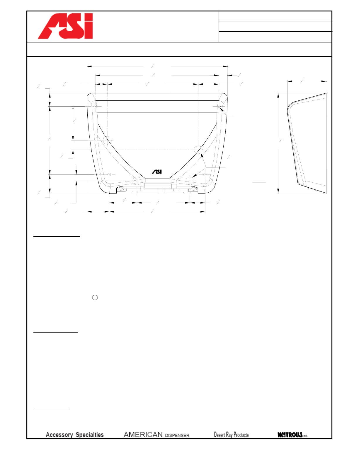
Mount unit in partition using No10 x 3/4" Philips oval head self-tapping screws (supplied). Holes in flanges are offset to prevent
screw interference. Install unit so that top of face trim is 57" to 61" (1448 to 1549) AFF (Above Finished Floor). Note partition
cutout is 7/8" (22) below top of face trim.
Partition Cut Out Required: 15-1/2"W x 28-7/8"H x ½”to 2"thick partition (394 x 733 x 13 to 51)
OPERATION
Push self-closing disposal door to deposit waste material. Doors operate independently and may be used simultaneously. Seat
covers are self-feeding until supply is depleted. Toilet paper rolls feed freely until depleted and level of supply is constantly
visible for low-level warning. Waste receptacle is emptied manually on cycle determined by maintenance needs. Toilet paper
rolls, paper seat covers and waste receptacle are serviced by unlocking and opening door. Locked door prevents inadvertent
dumping and unauthorized removal. Waste container safety-edged finger hole provides convenient grip for service. Toilet
paper spindles are carried in vandal resistant sub-frame accessible when door is opened. Barrier baffle panels preserve privacy
between stalls at all times.
15-38"
[391]
17-38"
[441]
30-58"
[778]
18-12"
[470]
16-38"
[416] NOTE: ALL DIMS ARE INCH [MM]
5-916"
[141]
28-58"
[727]
4-14"
[108]
1-58"
[41]
14"
[6]
12"-2"
[13-15]
57"-61" [1448-1549] AFF
18-12"
[470]
30"-34" (762-864) AFF REF
ADJUSTABLE
FLANGE
FIXED FLANGE
TUMBLER
LOCK
TUMBLER
LOCK
2-78"
[73]
6-916"
[167]