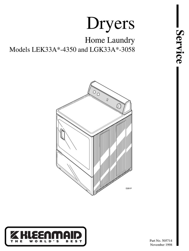
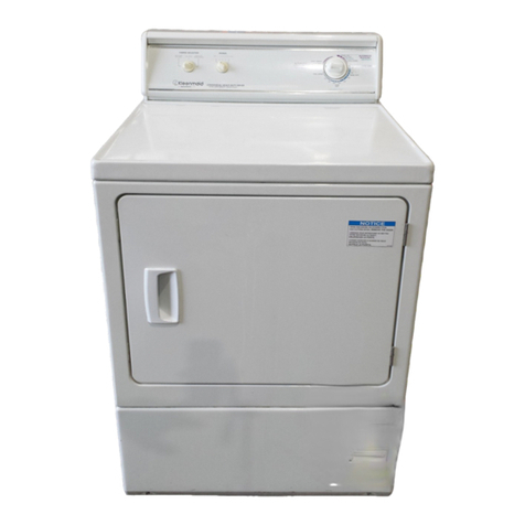
Kleenmaid KED2000 Setup guide

K
K
KL
L
LE
E
EE
E
EN
N
NM
M
MA
A
AI
I
ID
D
D
D
D
DR
R
RY
Y
YE
E
ER
R
R
R
R
RE
E
EP
P
PA
A
AI
I
IR
R
R
I
I
IN
N
NS
S
ST
T
TR
R
RU
U
UC
C
CT
T
TI
I
IO
O
ON
N
N
1SAFETY ........................................................ 2
2INSTALLATION............................................ 3
2.1 Basic installation ................................................................ 3
2.2 Exhaust vents...................................................................... 3
2.3 Feet (leveling legs).............................................................. 3
3OPERATION................................................. 4
3.1 Controls ............................................................................... 4
4COMPONENTS............................................. 5
4.1 Dryer Components.............................................................. 5
5REPAIR......................................................... 9
5.1 Disassembly / Reassembly ................................................ 9
5.2 Diagnosing (troubleshooting).......................................... 13
5.3 Dryer noise ........................................................................ 14
5.4 Customer diagnosing ....................................................... 14
5.5 NTC ratings........................................................................ 15
5.6 Control voltages................................................................ 16
5.7 Maintenance ...................................................................... 16
6FAULT DIAGNOSTICS............................... 17
6.1 Heater relay ....................................................................... 20
7TECHNICAL SPECIFICATIONS ................ 21
7.1 Dryer ratings...................................................................... 21
702_58300000135249_ara_en_a Page 1 of 21

1 SAFETY
cDanger of electric shock.
cWARNING Modern appliances are very powerful and use high
technology devices to safely control that power. Failure to use
the correct procedures and the approved parts can create
serious hazards for the person servicing the appliance and for
the user of an appliance with a bad repair. If you do not know
how to service the appliance, do not attempt to do so!
To avoid the risk of serious injury or death while servicing these
appliances:
cBe certain that all power is removed from the appliance before
beginning service.
cCarefully follow all servicing instructions. Verify the instructions
if there are any that you don't fully understand.
cRead and heed all Cautions and Warnings on the appliance
and those with the replacement parts.
cUse caution and proper protective gear when handling chassis
panels. Some of the edges that are not normally exposed may
be very sharp.
To avoid risk of serious injury or death to the users of the appliances:
cCarefully follow all service instructions.
cUse only parts authorized for the application.
cKnow the testing requirements needed to verify the safety of
the service action.
cUse proper, calibrated test equipment.
cDo all indicated safety tests and record results.
702_58300000135249_ara_en_a Page 2 of 21

2 INSTALLATION
2.1 Basic installation
Dryers shall be installed according to national and local codes.
2.2 Exhaust vents
2.2.1 Locating exhaust vent
Vent can be installed to the rear or right side of dryers. Rear factory
vent can be changed to the right side by moving the connector to the
side and the cap to the rear. Rotate both to the left to remove and to
the right to install, aligning the cap/connector notch with the vent tab.
2.2.2 Installing vent ducts
For best drying, use shortest possible duct length and fewest # of
elbows.
Use the table below when selecting ducting.
# 90º Turns / Maximum Length
Elbows Rigid Duct Flexible Duct
0 20 m 14 m
1 17 m 11 m
2 14.5 m 9 m
3 12 m 7 m
4 9 m 5 m
2.3 Feet (leveling legs)
Using a level front to back and side to side, adjust feet (leveling legs)
until dryer is level. When moving dryers, screw in feet completely
before moving dryers to avoid damage.
To adjust feet
(leveling legs),
rotate left to right
to lower dryer.
702_58300000135249_ara_en_a Page 3 of 21

3 OPERATION
3.1 Controls
Controls are shown below. Rotate the knob to the desired drying
program and push the Start/Pause button.
Start/Pause button – Starts,
stops and interrupts drying.
Options
buttons Display
Lint filter LED – Reminder (only)
to clean the lint filter. There is no
sensor showing lint levels.
LED indicator
lights
Program (cycle)
selector knob
Additional options buttons
– Menu chooses options and
Select changes settings.
mCAUTION – The Lint filter LED is only a
reminder to empty lint screens. Dryers are
operating normally. There are no fault codes
or diagnostics associated with the LED.
702_58300000135249_ara_en_a Page 4 of 21

4 COMPONENTS
4.1 Dryer Components
Basic components are control module, electric heater, drive motor with
fan, two NTC temperature sensors, two hi-limit temperature
protectors, moisture sensor and broken belt switch.
4.1.1 Electric heater
Dryers have 2700W heaters, which include an NTC temperature
sensor and a manually resettable hi-limit temperature protector.
NTC temperature sensor
Heater
terminals
Front (bearing) shield
Control module Push red
button to
reset Hi-limit
p
rotector.
Hi-limit protector
Fan
Moto
r
4.1.2 Drive motor
Drum
Fan wheel
shaft
Heater
Heate
r
Motor is rated 220-
240 VAC, 50 Hz, 1/3
HP (248.5 W), 3.0 A,
1425 RPM, 40ºC
ambient, class F
insulation. It drives
the fan (in front) and
drum (in rear, using
pulley shown).
Fan
Broken belt switch Drum belt
pulley
702_58300000135249_ara_en_a Page 5 of 21

4.1.3 Lint screen sensors
The front (bearing) shield contains two sensors – accessible after the
lint screen is removed. Along with the heater NTC and hi-limit
protector, the lint screen NTC and hi-limit protector provide
temperature regulation and safety.
4.1.4 Broken belt switch
The broken belt switch prevents the dryer from running if the belt has
broken or been left disconnected. It must be manually reset (by
pushing the left plunger in (viewing rear of dryer) – the dryer will not
run if the switch hasn’t been reset.
4.1.5 Air exhaust duct
Air exhaust duct connects to the fan and allows exhausting through
the rear or right side of dryers.
Side
Rear From fan
Hi-limit NTC
Hi-limit
NTC
4.1.6 Fascia (control) panel
Fascia panel contains knob and all buttons – knob and buttons are
factory built into the panel and cannot be obtained separately.
Push left plunger (toward
right) to reset broken belt
switch whenever drum or
belt has been removed for
any repair.
702_58300000135249_ara_en_a Page 6 of 21

4.1.7 Moisture sensor
Moisture sensor consists of two electrodes (located just left of the lint
screen on the front bearing shield). Moisture from clothes completes
the circuit between the two sensors, showing clothes aren’t dry.
Placing the moisture sensor on the front shield eliminates sensors
inside drums and conductance brushes outside drums.
4.1.8 Door pin
Door pin engages the door switch, notifying the dryer the door is
closed for drying. If the door pin is damaged, the entire door
assembly must be replaced.
A T-20 screw on the door pin cover can be tightened to align the door
pin. Don’t over tighten the screw.
4.1.9 Door switch
Door switch engages the door pin, turning the light on and off and
notifying the dryer the door is closed for drying. To remove it, push
the two latches inward and slide the switch toward the rear of the
dryer.
Latch
Latch
Door pin
702_58300000135249_ara_en_a Page 7 of 21

4.1.10 Door glass cover
The plastic door glass cover can be replaced by carefully prying it out
and snapping it into place.
4.1.11 Front felt drum seal
Dryers have a self-adhesive, Teflon coated, felt front seal which can
be replaced. When replacing the seal, make sure all old adhesive is
removed and no new adhesive gets onto the drum. Any excess
adhesive or residue may cause squeaking.
4.1.12 Drum with bands
Drums have two steel bands around them to make them quieter.
Drum Band
Belt
Felt seal
4.1.13 Empty drum detection
Felt seal
Drum wheels
Dryers shut down after 11 minutes if no moisture is detected. Dryers
can be immediately restarted.
702_58300000135249_ara_en_a Page 8 of 21

5 REPAIR
mCAUTION – 75% of all controls
returned for analysis check out OK. Most
control issues are due to loose connections.
5.1 Disassembly / Reassembly
5.1.1 Fascia (control) panel
Carefully pry off four screw cover, remove four T-20 Torx screws and
lift up panel.
5.1.2 Control module
Remove control module from fascia panel progressively from left to
right, carefully releasing inside and outside plastic latches (1-8 below)
so latches don’t break. Gently pry up left side of control so latches
don’t re-close. Module will release from fascia panel and knob.
Don’t cut cable mounts – cut cable ties holding cables to mounts.
When reassembling, use new cable ties.
5.1.3 Top panel (worktop)
Remove two T-20 Torx screws (with washers) from rear of dryer, slide
panel toward rear of dryer (~ ½ cm) and lift up panel. When
reassembling, place panel over two plastic mounting tabs, slide panel
forward and replace two screws.
T
-
20
5.1.4 Rear panel
Remove top panel (5.1.3). Remove two T-10 Torx screws holding
rear panel to rear exhaust vent. Remove T-20 Torx screws holding
rear panel to frame and to mains connection sheet. Lift panel out.
Pry moduleLocate module tabs
1
2
3
4
5
6
7
8
Cord terminals
outside dr
y
e
r
Mains
connection
sheet RFI filter and
cord terminals
inside dryer
702_58300000135249_ara_en_a Page 9 of 21

5.1.5 Drum and drum cover (with drum bearing)
1) Remove rear panel (5.1.4).
2) To remove belt tension, disconnect belt (from motor pulley).
3) Remove dryer shaft clip and two T-20 Torx drum cover screws,
then lift cover from dryer. Drum cover holds drum rear bearing,
so drum isn’t supported once drum cover has been removed.
4) Drum sleeve bearing can be removed from drum cover by
removing four T-20 Torx screws.
Drum (sleeve) bearing
Outer bearing race
Drum axle
5.1.6 Heater
Drum
Drum cove
r
Belt
Belt
Disconnecting belt
Remove rear panel (5.1.4) and drum cover (5.1.5). Disconnect wire
harnesses, then slide heater toward rear of dryer. When sliding
heater back into dryer, make sure heater tabs engage slots.
Drum
cover
Drum
shaft cli
p
702_58300000135249_ara_en_a Page 10 of 21

5.1.7 Motor, belt tensioner and broken belt switch
All three are mounted on motor cradle, located behind air duct
(viewing rear of dryer), and can be accessed from front or rear of
dryer. Motor must be disconnected from fan (5.1.9) and belt from
motor pulley before motor can be removed. Once disconnected,
motor cradle with motor, belt tensioner and broken belt switch can be
unscrewed and slid out from dryer. To remove motor from cradle,
remove two spring clips and lift up from cradle.
5.1.8 Front panel and bearing shield
1) Remove fascia panel (5.1.1). If necessary for access, remove
top panel (5.1.3).
2) Remove door and door hinge.
3) Remove two T-20 Torx screws at top and bottom of panel, then
lift panel up (from six plastic mounting tabs).
4) To remove belt tension (so drum doesn’t shift when front
bearing shield is removed), remove rear panel (5.1.4) and
disconnect belt (from motor pulley).
5) Disconnect door seal from front bearing shield, then remove
shield by removing T-20 Torx shield screws.
Belt tensioner
Motor
Broken
belt
switch
Slide out
Screw Screw
Cradle
Cradle
Motor
Tab
Fan screw
Cradle tab
Motor
cradle
702_58300000135249_ara_en_a Page 11 of 21

5.1.9 Fan
Remove front panel and bearing shield (5.1.6). Remove fan front
cover to access fan. Fan is located on front of motor shaft, which has
left-handed thread. To remove fan from motor shaft, use a 1” wrench
and rotate fan (clockwise) from left to right.
When removing fan, hold motor shaft, not motor rotor fins, to avoid
damaging fins.
5.1.10 Anti Crease/end light
If the Anti Crease/end light is on while the display is off, an internal
switch (S3) on the control board has been damaged and the entire
control module has to be replaced.
5.1.11 Serial # (E-Nr) label
The serial # label is located below the door and shows the model (E-
Nr) and serial # of the dryer.
Turn cw to loosen (left-handed thread)
702_58300000135249_ara_en_a Page 12 of 21

5.2 Diagnosing (troubleshooting)
Problem Possible Causes Suggested Repairs
Power not on or has been disconnected. Reconnect and turn on power.
Door switch misaligned & doesn't get activated
by door pin.
Tighten screw (where door pin engages door switch) to realign front shield with door.
Do not overtighten screw.
Door pin broken, so door switch doesn't get
activated.
Replace entire door.
Control module failed. Check control module output voltages (see section 5.6). Replace module if faulty.
Dryer won't run
Door switch or wire harness failed. Check door switch & wire harness resistances. Replace faulty part.
Motor overheated. Wait for motor to cool down and thermal protector to reset.
Broken belt switch tripped. Reset broken belt switch.
Motor control or motor failed. Check motor control voltage & motor resistance. Replace faulty part.
Lint screen hi-limit (thermal cutout) tripped. Clean lint screen and clean lint and other debris from front shield, then replace hi-limit.
Also check exhaust duct length & # of elbows.
Heating element failed. Check voltages to and resistances of parts. Replace faulty parts.
Heater hi-limit (thermal cutout) tripped. Correct what caused overheating, then reset hi-limit.
Heater won't work
Wire harness failed. Run resistance or continuity checks to track down broken wire or connector. Replace
failed wire harness.
Motor overheated. Wait for motor to cool down and thermal protector to reset.
Broken belt switch tripped. Reset broken belt switch.
Motor control or motor failed. Check motor control voltage & motor resistance. Replace faulty part.
Motor won't work
Lint screen hi-limit (thermal cutout) tripped. Clean lint screen and clean lint and other debris from front shield, then replace hi-limit.
Also check exhaust duct length & # of elbows.
Wire harness failed. Run resistance or continuity checks to track down broken wire or connector. Replace
failed wire harness.
702_58300000135249_ara_en_a Page 13 of 21

5.3 Dryer noise 5.4 Customer diagnosing
Problem Possible cause Remedial action
Main plug not inserted or not
inserted correctly.
Insert main plug correctly.
A power supply fuse has
blown or circuit breaker has
tripped.
Replace fuse/turn on breaker.
Start/Pause button not
pressed.
Press Start/Pause button.
No program selected. Select program.
Door not closed. Close door.
In Time–Programs duration
not chosen.
Chose time via Select button.
Dryer doesn’t
start.
Start/Pause
indicator light
doesn’t
illuminate.
Ambient temperature below
5 °C.
Increase room temperature.
Filter dirty. Clean filter, then turn dryer off and
on again (see section 5.7.1).
Exhaust air duct is blocked or
is too long.
Clean or shorten exhaust air duct
then turn dryer off and on again.
Fault in program sequence or
malfunction.
Turn off dryer, leave to cool for 30
min. and then turn on again.
Restart program.
Program has
been
interrupted.
A warning
signal
sounded and
the display
shows E:01
and/or the
Filter indicator
light flashes.
The room/cabinet is not
adequately ventilated.
Provide an adequate supply of
fresh air and then turn dryer off
and on again.
No program selected. Select program.
Light bulb defective, light bulb
burned out.
Change light bulb.
No power supply. Guarantee power supply.
Drum light
doesn’t
function.
Light bulb is loose. Tighten light bulb.
Dryer has a noise
Is dryer level?
NO Level dryer
YES
Clean out debris
Check exhaust for
debris
Spin drum to check if
drum shaft is bent
Check if 4 drum bearing
screws are loose
REAR OF DRYER
Tighten screws NO
YES
NO
Replace drum
YES
Check front bearing
shield for cracks or
damage
Replace cracked
front bearing shield
Check if drum wheels
are worn, damaged or
noisy
YES
NO
FRONT OF DRYER
YES
Replace wheels
YES
NO
Check front of drum for
cracks
YES
Check rear of dryer
NO
Check if drum belt isn’t
centered or is damaged
NO
Center or
replace belt NO
Remove belt and check if
tensioning roller is worn,
damaged or noisy
Replace
tensioning roller
YES
Spin motor shaft and
check for noise
NO
Replace motor
YES Check front of dryer
NO
Replace drum
YES
Remove rear panel if not
already removed
Remove rear panel and run the dryer a few minutes to find the noise
Remove metal front panel
If belt or drum has
been removed, reset
broken belt switch (by
pushing in left plunger)
702_58300000121945_ara_en_a Page 14 of 21

Problem Possible cause Remedial action
Start/Pause
indicator light
d
indicator
lights.
The display
shows 0:00.
l for 30
min. and then turn on again.
doesn’t
illuminate.
Anti
Crease/en
Fault in program sequence or
malfunction.
Turn off dryer, leave to coo
Restart program.
Moisture sensor dirty. Clean moisture sensor, then
dryer off and on again.
turn
Exhaust air duct is blocked or
too long.
Clean exhaust air duct or sh
it below maximum length
orten
allowed.
Turn dryer off and on again.
Filter dirty. Clean filter and then turn dryer off
and on again
Laundry was too wet. Spin laundry at higher speed in
the washing machine. Turn dryer
off and on again
Unsuitable program selected. gram and then
Select suitable pro
turn dryer off and on again
Maximum drying time
exceeded.
Clean filter and exhaust air duct.
Spin laundry at a higher speed in
your washer (t
water).
o remove more
Motor limit temperature was
exceeded.
Turn off dryer, leave to cool for 30
min. and then turn dryer off and
on again.
Degree of
drying has not
been reached
or the drying
time is too
y may
.
s not set
correctly.
for degree of
dryness.
long.
Displa
indicate E:03
Degree of drynes Change settings
5.5 NTC ratings
5.5.1 NTC R2 ratings (@ heater)
5.5.2 NTC R3 ratings (@ lint screen)
• @ 25ºC (77ºF) = 10 kΩ
• @ 40ºC (104ºF) = 5.3 kΩ
• @ 50ºC (122ºF) = 3.6 kΩ
• @ 60ºC (140ºF) = 2.4 kΩ
Hi-limit
NTC
Heater
NTC
• @ 25ºC (77ºF) = 25 kΩ
• @ 50ºC (122ºF) = 7.2 kΩ
• @ 80ºC (176ºF) = 2.4 kΩ
• @ 100ºC (212ºF) = 1.3 kΩ
702_58300000121945_ara_en_a Page 15 of 21

5.6 Control voltages
□Hea
□
□
□
□Sen
□NTC
□
□Hi-l
□
te
Pump motor (M8) – 240 VAC
Lamp (E8) / Door lock (F1) – 240 VAC
sor, door lock (F1) – 5 VDC
, heater (B20) – 5 VDC
NTC, lint screen (B21) – 5 VDC
imit (HTC), lint screen (F32) – 240 VAC
Broken belt switch (F34) – 240 VAC
oist – 5 VD
g
r (E1) – 240 VAC
RFI filter (R2) – 240 VAC
□M
Numbers in
diagram.
ure sensor (B25) C
parentheses “()” refer to part designations from the wirin
5.7 Maintenance
5.7.1 Cleaning lint filter
The lint filt
on after e
running) to remind customers
occurs when dryer runs too hot due
vent duct. When
1. Immediately stop dryer by rota Off
position, then open do
2. Remove and clean filter.
3. Replace filter and let dryer cool down.
4. Close door, then rotate cycle selector knob to desired cycle and
press .
If the
with dis
clogged ov
er should be cleaned after each use. The Filter light comes
ach cycle and when the door is open (while the dryer is
to clean the filter. An E:01 error code
to clogged lint filter or exhaust
E:01 error code occurs:
ting cycle selector knob to
or.
Start/Pause button to restart dryer
E:01 error code keeps occurring, clean the lint filter (by hand)
h soap and water. The lint filter is very fine and can be
er time when fabric softener or softener sheets are used.
702_58300000121945_ara_en_a Page 16 of 21

6 FAULT DIAGNOSTICS
2. S c
Obs c
Display
ele ting the test program
erve orrect method for setting program selector!
LEDs(Indicator)
y Cupboard
dry
End
Display
Button
LED Drying Iron dr
Activ e
men
ate t st Program selector switch to OFF position Off
u:
One time last errorTurn the appliance on by pressing the Start
and Delicates button simultaneously and
Start is
flashing
turning the selector switch (either direction). quick
Activ e is
flashing
quick
ate t st In test menu set program selector switch to
program: a test program:
Read out error storage
1st position to the right
2nd position to the right
Test program for safety test
3rd position to the right
Display test (LED/LCD)
4th position to the right
Control elements test
5th position to the right
Consumer test
6th position to the right
Laundry resistance measurement test
7th position to the right
Demo program
8th position to the right
Changeover 10A/16A (208V/240V)
operation
1st position to the left
Automatic end-of-line program
Start test
program:
Press START button LED Start is illuminating
Abort test
program:
Adjust program selector switch or press
START button
LED Start is flashing
Switch off appliance
Leave test
program:
Switch off appliance
t on one side with the phase ) switch on. The test must be done using
For this propose the following Inspection Process is adaptive
Connect app ine
tton Extra dry
4. The current consumption on tester (Motor and Heater Elements must be switch on)
1. Safety test
For the safety test must Heater Element (at leas
different current method.
1. liance with tester and power l
2. Choose program with Heater; example Co
3. Program start
The Maximal Different Current must be under allowable limit while checking procedures is running.
Annotation:
Depending on used tester (for example Meratester 5-f) can be necessary inspection process with 180° twisted power
connector ones again do.
Inspection Process must be done with cold Appliance to prevent that Heater Element is switch on.
2.1 Fault display
DisplayTest: Sequence:
Standard Indicator Display
E: failure number
C: numbers of failure
Last fault - the last fault is displayed at first Start and finished LED’s are E:XX is displayed
flashing
Fault history - after further operation the START button, the
content of the error register (of the last 8 cycles)
is indicated
LED Start is illuminating
Status-LED’s: failure code
E:XX is displayed
C:XX is displayed
Or blank if no failure
Last fault - if all register were indicated, the first fault is Filter- outflow hose LEDs E:XX is displayed
displayed again by operation the START button are flashing C:XX is displayed
Or blank if no failure
LEDs (Indicator)
Drying Iron dry Cupboard dry End description cause
Display Fault / fault Remarks, possible Results
No fault
is
flashing
E:11 Fluffing level 1 - Fluff filter, container
or air routes blocked
- Clean components
and air routes
is flashing E:12 Fluffing level 2 - Fluff filter, container
or air routes blocked
- Clean components
and air routes
is
flashing
is flashing E:13 Maximum drying
time exceeded
- Heater or heater
control damaged
- Bimetal switch was
triggered
- Laundry load (to
heavy or to wet)
- Check heating
circuit and bimetal
switch, replace
damaged parts
- Reduce laundry
load or select
adequate program
is
fl
ashing
is flashing E:15 Fault in heating
circuit
- Excess temperature
of the heater is
detected
- Check air routes,
heater function and
heater control;
replace damaged
parts
is
fl
ashing
is flashing is flashing E:17 Door-NTC fault
(TD)
- Damaged sensor
- Short circuit in sensor
wire
- Open sensor circuit
- Control interpretation
fault
- Check wires and
connectors, replace
damaged parts
- Short circuits and
breaks are detected
by control after
switch-on
702_58300000121945_ara_en_a Page 17 of 21

LEDs (Indicator)
Drying Iron dry Cupboard
dry
End
Display Fault / fault
description
Remarks, possible
cause
Results
is flashing E:18 Heater-NTC fault
(TH)
- No temperature rise
after starting a program,
break in heater circuit,
- Damaged sensor
- Short circuit in sensor
wire
- O
- Check heater circuit and
bimetal switch, replace
damaged parts
- Check sensor wire,
check connectors; replace
damaged parts
- Sh ts and breaks
of wires are
etected by control after
switch-on
pen sensor circuit
- Contro
fault
l interpretation
d
ort circui
the sensor
is flashing is flashing E:20
is flashing is flashing E:21
is flashing is flashing is flashing E:22
is flashing is flashing is flashing E:24
is flashing is flashing is flashing E:25
Control faul
lid)
Proces oftware s t
incorrect program d
software or
repl
t 1
(Update inva
- s s e
is e
- Update
ace control
is flashing is flashing is flashing is flashing E:26 Control fault 2 - Control fault is
detected
lace control- Rep
2. est P Test
e Display
2 T rogram for Safety
T st: Sequence: :
START butto ter will with the
ngle sited connected
LED Start is illuminatingn Starts the motor, the hea
centrifugal switch si to
mains voltage
- Do Safety Test
START butto ith pushing the start button LED Start is flashingn - Program ends w
Depending on used tester can be neces ry
process with 180° twisted power
es again do.
sa
inspection
connector on
2.3 Indica d LCD)
Display:
tor Test (LEDs an
Test: Sequence:
START butto /or LCD segments are illuminating
continuously for 4 sec.
All LED and/or LCD segments are illuminatingn - All LEDs and s
CD segments are activated All LEDs and/or LCD segments are illuminating
successive in 0.5 sec steps
- All LEDs and/or L
successive in 0.5 sec steps
- Sequence starts again
2.4 Opera
ting Elements
Test: Sequence: Display:
START butto utton uminatingn - Press a START b LED Start is ill
OPTION butt e pressed button is illuminatingons - Press OPTION buttons successiv LED of the
CHANGE bu the seven segment display inclusive the
colon and the dot are illuminating.
tton - Press a CHANGE button All segments of
MENU butto button Another existing segments (excepting the colon, the dot)
of the LC display are illuminating.
n - Press a MENU
Program selector - Select each position with the program selector Illuminating elements see the table below
buzzer - Keep pressed the MENU button Continuous output of the acoustic signal sound level
steps inclusive "0"
LEDs Position
or display Off 1 2 3 4 5 6 7 8 9 10 11 12 13 14 15 Off
symbol
Dr g X X Xyin X X X X X
Iro Dry X X X Xn X X X X
Cupboard Dry X X X X X X X X
An rease/End X X X X Xtic X X X
2.5 Consumer test
Prüfung: Ablauf: Anzeige:
Motor u. Heizung - Motor u. Heizung werden mit einem zeitlichen Siehe Tabelle
Ablauf angesteuert
Time/s
absolute 0 5 10 15 20 25 30 35 40 45 50 55 60 65 70 75 80 85 90 95 100 105 110
Duration/s 5 10 60 30
LED Drying X X
LED Iron dry X X
LED Cupb
Dry
oar
d X
Display :01 :02 :03 :04
Motor
O
n
Of
f
Heating
On
Off
2.
6 Laundry resi ance mea ure te
est: q nce: sp
st s ment st
T Se ue Di lay:
- Open the dryer door
- Th function of the induc inpu
tested by making a short circuit betw
conductance electrodes and the drum
e tance t can be
een the
702_58300000121945_ara_en_a Page 18 of 21

2.8 Changeover 10A/16A (208V/240V) operation (EU: not used, function without any
s)
S n p
Test descriptio lay symbol L pla emn: LED or disp
Drying
ED or Dis
Iron Dry
y symbol R arks:
O Off Fault bypass in measuring circuit.ff ! There is a
O On ff No fault
- Drum empty, no
connection
between
conductance
electrode and drum
Off
circu
On Fault! There is a bypass or sh
it.
ort- circuit in measuring
Off Off No fault
On Off Fault it
circu
! There is a open circu or resistance in measuring
it is too high
- Bypass on the
conductance
electrode with the
hand or with define
resistance of
100kOhm...1MOhm
Off On Fault
circ
! There is a bypass or sh
uit.
ort- circuit in measuring
- electrical
onnection
c
between
conductanc
lectrode a
e
e nd drum
O O Fault ing
cu
ff ff ! There is a open circuit
it is too high
or resistance in measur
cir
2.7 Demo program
rüfung: Sequence: Display:
P
START button The demonstration program
sequence on the display an
simulates a program
d uses the status
dingly.
Siehe Tabelle
LED’s accor
Consumers are not activated during the d
program.
emo
Step Time tes/ All Status LC DisplayLED for Delica
Reduced Ironing LEDs
1 1 s Off blankOn
2 1 s Off On blank
3 1 s On Off blank
4 1 s blankOff On
5 1 s blankOn Off
6 1 s On blankOff
7 30 s Off only drying -LED ON Counts from 0:30 to 0:00 descending
8 5 s Off only Anticrease / End -LED ON 0:00
9 1 s On Off blank
10 1 s On blankOff
11 1 s On Off blank
12 1 s On blankOff
13 1 s On Off blank
14 1 s Off On blank
15 10 s only drying -LED ON Counts from 0:30 to 0:20 descendingOff
16 10 s Off only “Damp Dry” -LED ON Counts from 0:20 to 0:10 descending
17 10 s Off only “Regular Dry” -LED ON Counts from 0:10 to 0:00 descending
18 5 s Off only Anticrease / End -LED ON 0:00
19 back to step 1
effect
Test: eque ce: Dis lay:
START button i del ate angeabl
ED art is illumi ting
ele n lo (10
- Delicates LED: O
Disp y: „lo“
le n h (1
- Delicates LED: On
- Display: „hi“
State w th ic s button ch e L
S
St
ctio
w
na
A)
ff
- la
Se ctio igh 6A)
START button Abort program for storage LED Start is flashing
2.9 Automatic end-of-line program
Test: Sequence: Display:
Taste START h te p ra is e o t to ti ly
l o t
he sture sensor input must co ted with a
M resistor (+/-5%) , while th is
D a s m
T
th
is
e co
st
ntro
rog
l fun
m
ction
us
s du
d t
ring
tes
app
au
ianc
ma
e pr
cal
duc
ion.
T moi
Ohm
nnec
e st
2 te
running.
LE St rt i illu inating
2.9 Automa e line program
Test: Sequence: Display:
tic nd-of-
Taste STAR This test program is used to test aut matically
the trol functions during applianc production.
The moisture sensor input must connected with a
2M resistor (+/-5%) , while the st is
running.
LED Start is illuminating
T o
con e
Ohm te
Seque r yer
Time/s
12 13 14 15 16 17 18 19 20 21 22 23 24 25
nce Elect ical Dr
absolute -1 0 1 2 3 4 5 6 7 8 9 10 11
Duration/s 4 s 4 s 12 s 5 s
On
Motor
Off
On
Heater
Off
On
NTC Test
Off
On
Moisture
Sensor
Test
Off
702_58300000121945_ara_en_a Page 19 of 21

Failure Code fo
LED->
rt ne test program
g damp dry
he li
dryin regular dry extra dry lint filter
NTC in th
channel
e exha E:17 X
ust
NTC above the
heater
E:18 X
Overheating E:11 und E:12 X
Conductance
error(*)
X
6.1 Heater relay
Heater rel board the control mod there’s additional heater
screen NTC’s detect
overheatin clogged vent ducts), an E:01 fault code will
e test program (7.2)
1. 11 Overheati (fluffing) level 1. Heater temperature rose
or an 8ºC in econds once.
2. 12 Overheati (fluffing) level 2.
or an 5ºC in econds 25 times.
3. 5Heater fa pe
5º or lint scre temperature rose more than 85ºC. Motor
d ater shut o
e mean he r relay contact has f . To check heater
relay, run nsumer T ition)
ren ur Step 2 (5 tes l
w ). Motor should be on and heater should be off – if so,
ontrol is OK and shouldn’t be replaced. If heater and motor turn on
together during Step 2, relay has failed and control must be changed.
ay is on ule –
relay diagnostics on the control. If heat
g (e.g. from
er or lint
appear during drying. Running customer servic
and checking fault codes can show any of the following codes:
E: – ng
m e th 5 s
E: – ng Heater temperature rose
m e th 5 s
E:1 – ilure. Heater tem rature rose more than
11 C en
an he ff.
E:15 cod can ate used
Co est 2.5 (5th pos and check total dryer
cur t d ing -15 seconds after t started – display wil
sho “.02”
c
Notes:
•Don’t reset control after fault codes occurred. Fault codes are
aut ly cleared after ng cycles without failures. If
r on and off 8 times
successively.
•
only when motor is running or shuts off, heater
omatical 8 dryi
fault codes “must” be clea ed, turn dryer
Heater is connected to motor centrifugal switch, so heater runs
. When mot
shuts off.
702_58300000121945_ara_en_a Page 20 of 21
Other manuals for KED2000
1
Table of contents
Other Kleenmaid Dryer manuals

Kleenmaid
Kleenmaid LEK33A-4350 Series User manual

Kleenmaid
Kleenmaid KED2000 User manual

Kleenmaid
Kleenmaid Automatic dryers User manual

Kleenmaid
Kleenmaid KCDV60 Installation guide

Kleenmaid
Kleenmaid KED601 User manual

Kleenmaid
Kleenmaid KED500 User manual

Kleenmaid
Kleenmaid KED602 User manual

Kleenmaid
Kleenmaid LEK37A User manual

Kleenmaid
Kleenmaid KCDV60 Installation guide

Kleenmaid
Kleenmaid KED300-Compact User manual