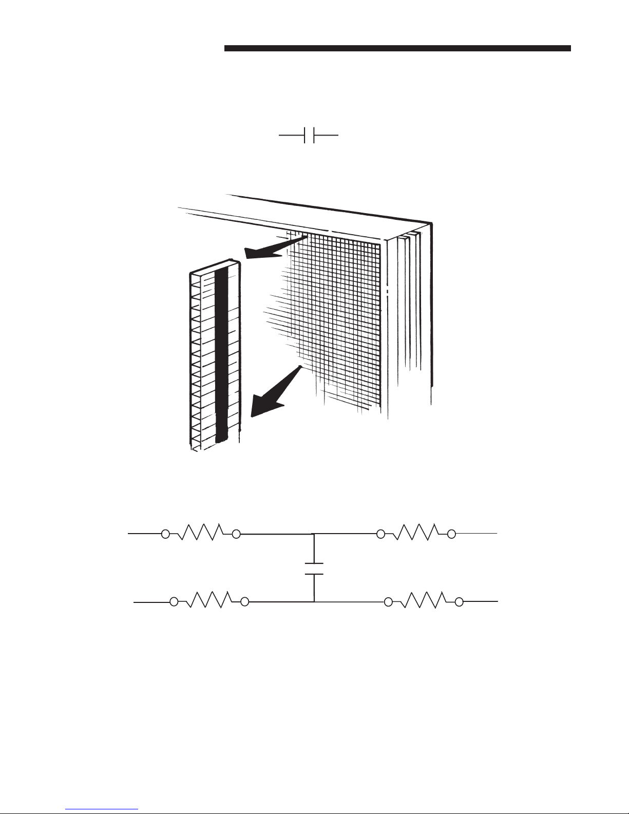
American Standard IFD AIR CLEANER User manual

IFD AIR CLEANER SERVICE MANUAL
PUB NO. 34-3446-01

© 2005 American Standard Inc. All Rights Reserved SF
Service Manual
1) Pre-filter - traps large particles such as hair and lint before
they can enter the cell section.
2) Field Charger - Charges the contaminants
3) Collector Cell (2) - removes and collects small impurities
from the air.
4) Cabinet - mounts between the furnace/air handler and
return air duct work and houses the collector cells, field
charger and pre-filter.
COMPONENTS OF THE AIR CLEANER
11
11
1
22
22
2
33
33
3
44
44
4
55
55
5
77
77
7
66
66
6
88
88
8
33
33
3
11
11
122
22
233
33
3
AIR
FLOW
1
5) Power Door -the solid state power supply components
that convert the 24 Volt AC to the high-voltage, direct
current required to power the field charger and cells. Allows
access to the fluted collector cells, field charger and pre-
filter.
6) Transformer - supplies 24 Volts to the indoor unit and air
cleaner
7) 24 Volt Power / Control Cable
8) Gasket, Literature and Hardware Packet
THEORY OF OPERATION
Air in the home is circulated through the heating and cooling system, maintaining the temperature at a comfortable
level. At the same time, the circulated return air is passing through the indoor equipment millions of small air-born
particles such as smoke and pollen, most of them are to small to be visible, are carried by the returning air to the
Electronic Air Cleaner. The reasons this Electronic Air Cleaner efficiency is so superior to previous models is the new
design of the ionizing section call the field charger section and the radical departure from charged metal collector
plates to charged insulated collector cells. The air-born particles in the return air pass through the field charger section
where the positive high voltage ionizer pins are located. The positive high voltage on the field charger pins will cause
the air-born particles passing by them to become positively charged. The collector cells surfaces are insulated from the
high voltage, which will reduce electrical arcing noise. These charged collector cells attract and hold the positively
charged air-born particles to their negative insulated charged surfaces. An electrostatic electronic air cleaner makes
use of the basic law of attraction, opposite charges attract.
▲WARNING
!
RISK OF ELECTRIC SHOCK: These servicing instructions
are for use by qualified personnel only. To reduce the risk of
electric shock, do not perform any servicing other than that
contained in these operating instructions unless you are
qualified to do so.

SF 3
Service Manual
FIELD CHARGER IONIZER PINS ARE POSITIVE CHARGED.
AT THE NORMAL POWER SETTING THE IONIZER PINS WILL HAVE
9,600 VOLTS DC APPLIED TO THEM.
THE POWER SETTING CAN BE CHANGED IN THE SET UP MODE OF
OPERATION.
COLLECTOR CELLS ARE INSULATED CELLS WITH ONE SIDE OF THE
CELL POSITIVELY CHARGED AND THE OTHER SIDE OF THE CELL
NEGATIVELY CHARGED. A POSITIVELY CHARGED AIRBORNE
PARTICLE WILL BE ATTRACTED AND HELD IN PLACE TO THE
NEGATIVELY CHARGED AREA OF THE COLLECTOR CELL.

4SF
Service Manual
COLLECTOR CELL CONSTRUCTION
Collector cells start out as a strip of corrugated box plastic strips. On the top and bottom of the strip a conductive
ink strip is applied. These inked plastic strips are then glued together, one on top of the other forming the collector
cells. Electrically the cell is now a capacitor.
Capacitor Symbol
10 meg ohm resistors are placed in each leg of the cell to limit high current surges.
The standard Digital Ohm Meter will not read over 10 meg Ohms. The total resistance from the Collector High
Voltage input terminal to it’s High Voltage output terminal is 20 Meg Ohms.
10 Meg Ohms 10 Meg Ohms
Cell Strips
OUTPUT INPUT

SF 5
Service Manual
Collector Cell
Collector Cell Guide Strips
CAUTION
!
Do Not expose filter to UV light. UV light can cause plastic
material to deteriorate which may lead to filter damage

© 2005 American Standard Inc. All Rights Reserved SF
Service Manual
BLUE
RED
GROUND (BLK)
TRANSFORMER
Wall Mount Transformer
Wiring Diagram and
A/C Voltmeter Test Hookup
Power / Control
24 V
Common
Furnace
Heating Signal
Fan Signal
WIRING DIAGRAM
ELECTRICAL CONNECTIONS
The air cleaner requires 24 Volt AC power and indoor fan
signal for heating call to operate. A transformer adequately
sized to power both the system and air cleaner is provided
with the air cleaner.
NOTE: A 50 VA transformer is required for Furnace
applications and 75 VA required for Air Handler applica-
tions. If the indoor air handler already has a properly
sized transformer, no replacement is required.
Plug the air cleaner power/control cable into the air cleaner
door and route the cable into the indoor unit low voltage
wiring location.
NOTE: If Volt meter reads above 10
VAC, reverse the 24 Volt AC leads
coming from the wall mounted trans-
former to the Electronic Air Cleaner
cable plug.
2
3

SF 7
Service Manual
DISPLAY FEATURES (Fig. 4)
The air cleaner display can be used for several functions.
• Provide the homeowner the operating status of the air
cleaner, including an indication the pre-filter or cells need
cleaning.
• The installer access the set-up mode to change the time to
clean settings for the pre-filter and collection cells as well as
reduce the ozone generated by the air cleaner if needed.
• The unit will display fault codes for the homeowner indicating
there is a problem with the air cleaner and various fault codes
for the service technician to assist in troubleshooting the
problem.
AIR CLEANER OPERATION
Turn the electronic air cleaner on by pushing and releasing
the Power button . The back lighted Power and Filter
Reset buttons will illuminate along with the first green LED
(G1) indicating 24 volt power is present to the air cleaner.
When the indoor fan is operating the first LED (G1) will
slowly flash. This indicates the field charger and collection
cells have power and the unit is operating normally. There is
a slight time delay between the indoor fan starting and LED
(G1) flashing. Time delay for "G" fan is 10 seconds. Time
delay for heating is 90 seconds.
NOTE: There is a 10 minute delay after the indoor fan operates,
before the air cleaner starts to operate, each time the power to
the air cleaner is turned off/on. This can be bypassed by going
into and then out of the set-up mode
SET-UP MODE
A combination of RED, YELLOW, and GREEN LED's are
used to indicate the following settings.
• The three GREEN LED's are used to indicate pre-filter
cleaning interval. This is measured in actual run time of the
indoor fan. The default setting is 2 months.
• The four YELLOW LED's indicate the collection cell cleaning
interval. This is measured in actual run time of the indoor fan.
The default setting is 6 months.
• The three RED LED's indicate the power setting. The default
setting is normal.
• A combination of flashing green, red and yellow LED's are
fault codes. See Fault Codes on Page 9.
SET-UP MODE OF OPERATION
To enter the Set-up Mode press and hold both the Power and
Reset buttons for a minimum of 5 seconds. The display will
go blank and then the programmed settings are displayed. If
this is the desired setting or at any time you want to exit the
set-up mode, press and hold BOTH the Power and filter
Reset buttons for a minimum of 5 seconds to exit.
To change any of the settings, press the Power button once.
PRE-FILTER SETTING (Fig.5 )
One or more of the GREEN LED’s will come on indicating
the pre-filter cleaning time setting. Repeatedly press the
Reset button to cycle through the time options for the pre-
filter cleaning cycle until the desired setting is displayed.
Press the Power button once to accept that setting and
move to the cell cleaning settings.
GREEN LED PRE-FILTER SETTINGS
1 Month 2 Months** 3 Months
G1
G2
G3
Y1
Y3
Y4
R1
R2
R3
Y2
CLEAN
DIRTY
G1
G2
G3
Y1
Y3
Y4
R1
R2
R3
Y2
CLEAN
DIRTY
G1
G2
G3
Y1
Y3
Y4
R1
R2
R3
Y2
CLEAN
DIRTY
CELL CLEANING SETTING( Fig.6)
One or more of the YELLOW LED’s will come on indicating
the collector cell cleaning time setting. Repeatedly press the
Reset button to cycle through the time options for the
collector cells cleaning cycle until the desired setting is
displayed. Press the Power button once to accept that
setting and move to the power settings.
YELLOW LED COLLECTOR CELL SETTING
2 Month 4 Months 6 Months** 9 Months
G1
G2
G3
Y3
Y4
R1
R2
R3
Y2
CLEAN
DIRTY
G1
G2
G3
Y3
Y4
R1
R2
R3
Y2
CLEAN
DIRTY
Y1
G1
G2
G3
Y3
Y4
R1
R2
R3
Y2
CLEAN
DIRTY
Y1 Y1
G1
G2
G3
Y3
Y4
R1
R2
R3
Y2
CLEAN
DIRTY
Y1
5
6
LED DISPLAY
** Factory Setting
In normal operation, the air cleaner may make a slight sound
as the air passes through it and is cleaned. In some
applications, you may notice this sound coming from the
return air vent(s). If desired, this sound level can be
reduced with minimal impact on air cleaning efficiency by
reducing the power setting of the field charger in the set-up
mode

8SF
Service Manual
LitePort DATA
When the air cleaner has detected a fault and it is flashing it’s
three RED LEDs on and off it will also be sending the fault data
to the pre-filter LED causing it to flash on and off. This fault data
can be read using a LitePort Optical Coupler. To activate the
LitePort data port during normal operation remove 24VAC power
from the electronic air cleaner. Push and hold in the reset button
while applying the 24VAC power to the electronic air cleaner. The
LitePort data will then be outputted via the prefilter LED. The
LitePort data will now be continuously outputted until the 24 VAC
power is remover from the electronic air cleaner.
THREE RED LEDs & THE Pre-filter LED FLASHING
This means service is needed. For these THREE RED LEDs to
be flash on and off the control must have detected the SAME
FAULT, see Fault Code Table on page 9, THREE TIMES in a row
after an automatic High Voltage Shut Down cycle.
FAULT CODES RETRIEVAL
To retrieve the last three faults that the Air Cleaner Control
has detected enter the Set Up Mode of operation.
Press and hold the Power/On button and the Reset button
for a minimum of five seconds. When the control enters the
SET UP MODE of operation some of the Green, Yellow and
Red LEDs will be on. The color and number of LEDs that are
on indicates how the control is presently programmed. (See
SET UP CHARTS on a previous page). To enter the Fault
Codes section press and hold the Reset Button for ten
seconds. After ten seconds the main LED display will go out
for one second and then some of the LEDs may began to
flash on and off. If no fault has been detected then only the
first Green LED will be flashing on and off. The flashing Green
LED or LEDS identifies the fault number being reported out.
One Green Led flashing on and off means the last fault
detected is being reported out, two Green LEDs flashing
means the second fault detected is being reported out and
three Green LEDs flashing means the last fault stored in the
control memory is being reported out. The last three faults
detected will be stored in the control’s memory and the last
fault detected will be the first fault reported out.
You are now in the Fault Log report section and the last fault
detected is now being reported out.
To step through the faults press the Power/On button again
to get the second fault and again pressing the Power/On
button will take you to the last fault stored in the control’s
memory. Push the Power/On button again and the control
will again display the last fault detected.
To exit the Set-up mode, press and hold both thePower/On
and Filter reset buttons for a minimum of 5 seconds.
FAULT CODES
When a fault is being reported out check the position number
of any of the Yellow and Red LEDs flashing on and off.
Compare this combination of flashing LEDs position numbers
to the Fault Code chart to see which fault has been detected.
The number one Yellow LED will always be out in the Fault
Code report section.
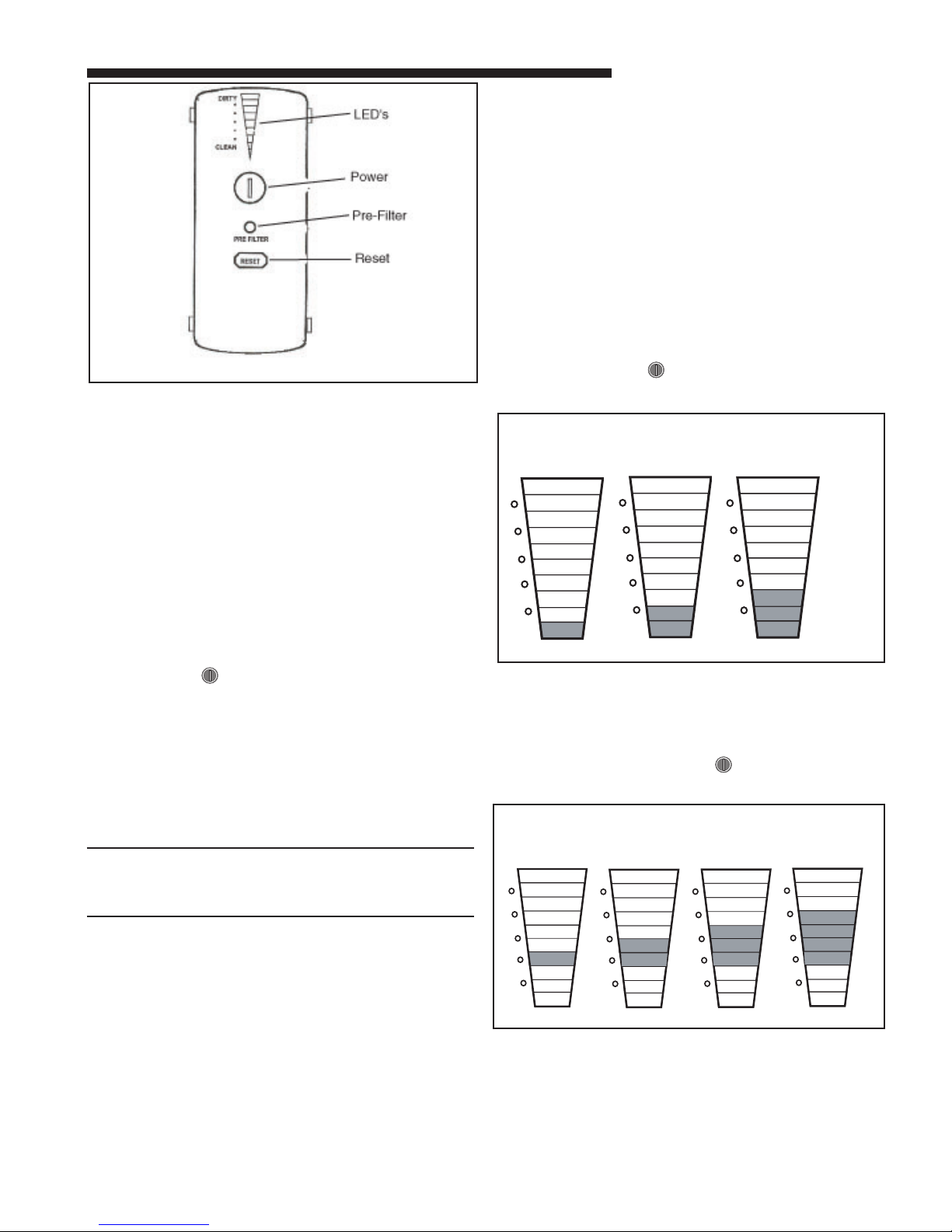
SETTING THE POWER LEVEL
All electronic air cleaners produce a small amount of
ozone that is within established limits. Some customers
may notice an odor especially at high altitudes and low air
flow rates.
The average person can detect the odor of ozone in the
range of 3 to 10 parts per billion (ppb) The air cleaner will
contribute 5 ppb of ozone to the indoor air on the
NORMAL setting. The U.S. Food and Drug Administration
recommends indoor ozone concentrations should not
exceed 50 ppb.
One or more of the RED LED’s will come on indicating the
Power setting. Repeatedly press the Reset button to cycle
through the Power setting options until the desired setting
is displayed.
To exit the set-up mode, press and hold BOTH the Power
and filter Reset button for a minimum of 5 seconds. The
current settings will be saved.
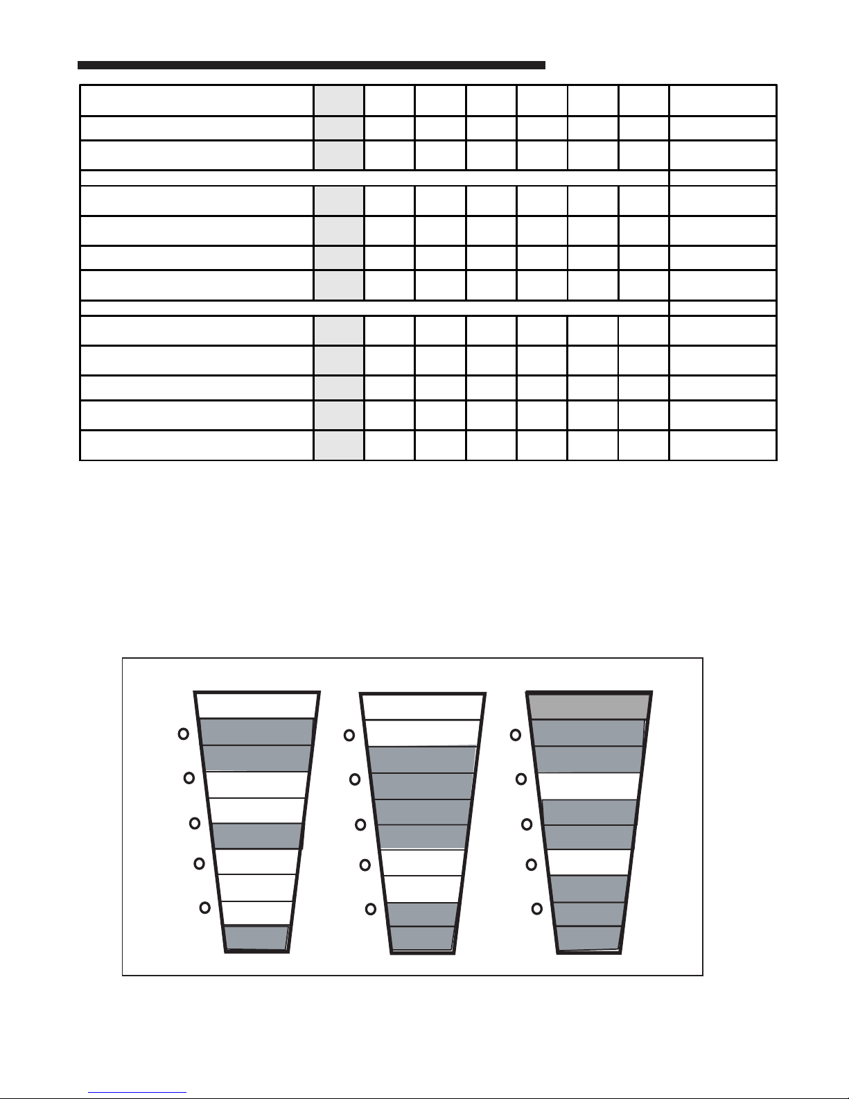
RED LED POWER SETTINGS
Lowest Medium Normal*
G1
G2
G3
Y1
Y3
Y4
R1
R2
R3
Y2
CLEAN
DIRTY
G1
G2
G3
Y1
Y3
Y4
R1
R2
R3
Y2
CLEAN
DIRTY
G1
G2
G3
Y1
Y3
Y4
R1
R2
R3
Y2
CLEAN
DIRTY
*Factory Setting
FAULT CODES
The air cleaner LED’s will display a fault indication, three
yellow or three red LED’s, when a fault has been detected.
A log of the last three faults is recorded and can be
accessed by going into the set-up mode. The unit will
repetitively check the system to determine if the fault
persists. The fault indication will be displayed as long as
the fault condition remains.
If the fault is no longer present, the system will return to
normal operation and no longer display the fault indication.
Even if the fault has been cleared, a log of the last 3 faults
is recorded.
THREE YELLOW LEDs FLASHING
These LEDs flashing on and off means that the Pre-Filter
or the Collector cells need to be cleaned. The air cleaner
control has detected ten consecutive automatic High Voltage
Shut Down (HVSD) cycles. An automatic HVSD cycle is
normally activated by the control system when an internal
electrical arc occurs.
7

SF 9
Service Manual
Examples: see fig. 8
Ex. #1: The most recent fault condition was a High Voltage “HV was Low”
Ex. #2: The second fault condition was “Internal Control Lockout”
Ex. #3: The third fault condition was “Input Current too High”
To clear the all three faults codes from the control’s memory press and hold the Reset button for 2-4 seconds when the fault codes
are displayed. When the fault memory is cleared the Yellow and Red LEDs will go out for all three fault locations. The Green LED or
LEDs will remain on to mark the fault number, first, second or third fault.
1. Check AC line voltage, is ship with transformer installed?
2. Check set up / Replace power door.
3. Remove power door and recheck high voltage-still low
replace power door, if now OK, check cells and field
charger.
4. Replace power door.
5. Clean Collector cells and Field Charger - If they are clean
check for arcing through the plastic frame.
6. Check set up / Replace door.
7. Check Collector cells and Field Charger connector pins.
8. Clean Collector Cells and Field Charger. Check for arcing
through the collector cell and field charger cases.
9. Repower air cleaner - check for normal operation.
Replace door if same fault comes back.
10. Check to see if buttons operate smoothly and are not
obstructed.
G1
G2
G3
Y3
Y4
R1
R2
R3
Y2
CLEAN
DIRTY
G1
G2
G3
Y3
Y4
R1
R2
R3
Y2
CLEAN
DIRTY
Y1
G1
G2
G3
R1
R2
R3
CLEAN
DIRTY
Y1
Y4
Y3
Y2
Y1
Ex 1. Ex. 2 Ex. 3
8
FAULT CODES YEL-1 YEL-2 YEL-3 YEL-4 RED-1 RED-2 RED-3 SERVICE
PROCEDURE
No Fault Detected OFF OFF OFF OFF OFF OFF
Input AC Voltage too Low ON 1
HV OUTPUT VOLTAGE FAULT
HV off when it should be on ON ON 2
HV too LOW ON ON ON 3
HV too HIGH ON ON ON ON 4
Repetitive Arcing ON ON ON 5
INPUT CURRENT FAULTS
Input Current off when it should be on ON ON ON 6
Input Current too LOW ON ON ON ON 7
Input Current too HIGH ON ON ON ON ON 8
Internal Control Lockout ON ON ON ON 9
One or More Buttons Stuck ON ON ON ON ON ON 10

10 SF
Service Manual
TESTING COMPONENTS USING THE UNIT’S OWN MICRO & LEDs
There are four tests that can be performed in the field. These Tests are for testing the High Voltage Relay, LEDs,
High Voltage Output and the Thermostat Inputs.
To enter the TEST Mode of this control perform the following.
1.Push and hold the Power Button until all ten LED come on, then release the Power Button . The air-cleaner is
now off and the LEDs should step off one at a time.
2.Press the Reset Button three times in a row within 20 seconds and the Prefilter LED will come on.
3.Quickly push and hold the Power Button and the Reset Button at the same time, the Prefilter LED will then go out
and then come back on flashing. The Prefilter LED will continue to flash as long as the control is in the test mode.
The Prefilter LED is now sending LitePort data.
4.There are three ways to exit the test mode, (1)remove power, (2)press the Power Button and the Reset Button in
and hold them in for five seconds or (3)do not push any buttons for five minutes.
5.The Green LEDs chart, below, will show which of the four tests you are in.
At this time the first Green LED should be on. This indicates that you are in the HV(HIGH VOLTAGE) Relay Test
mode.
6.There are three tests in the HV Relay Test section. See Chart below. A Yellow LED will show which test you are in.
Test 1 the 1st Yellow LED will be on, Test 2 the 2nd Yellow LED will be on and in Test 3 the 3rd Yellow LED will be on.
Push the Reset Button once to move to the next test in this section.
7.One of the three Red LED will indicate the condition of the each test.
When the Third Red LED is on this indicates that the High Voltage measured is out of range.
When the Second Red LED is on indicates that the High Voltage Current and Voltage are in their proper operating range.
When the First Red LED is on indicates that the High Voltage Input Current is out of range.
8.Push the Power Button once, this will move the control into the LED test Mode. All 10 barograph LEDs and the two
backlight LEDs below the two buttons should come on. The communication LED on the main printed circuit board
will light also.
9.By pushing the Reset Button you can cause one of the 12 LEDs after another to come on and go off.
10.Push the Power Button once, this will move the control into the High Voltage Output Test. There are four HV (High
Voltage) tests in this section. See chart below. A Yellow LED will show which test you are in. For Test 1 the first Yellow
LED will be on, Test 2 the 2nd Yellow LED will be on, Test 3 the 3rd Yellow LED will be on and Test 4 the 4th Yellow
LED will be on. Push the Reset Button once will move you in to the next test of this section.
TEST 1st Green LED 2nd Green LED 3rd Green LED
HV Relay Test ON
LED Test (All LEDs will initially energize upon entry into LED Test mode.)
HV Output Test ON ON
Thermostat Input Test ON
TEST Yellow LEDs Description
0% Duty Cycle on HV
Relay PWM output 1st Yellow HV relay should remain off. The control will
check the HV. It should be 0 volts.
HV Input Current Test 2nd Yellow
HV relay should remain off after brief double
click. The control will expect the HV output to
be 0 volts.
90% stepping down to 75%
Duty Cycle on HV Relay
PWM output
3rd Yellow Control will check the HV supply, it should be
9.6KV. +/- 600 volts

SF 11
Service Manual
11. One of the three Red LED will indicate the condition of the each test.
When the Third Red LED is on this indicates that the High Voltage measured is out of range.
When the Second Red LED is on indicates that the High Voltage Current and Voltage are in their proper operating
range.
When the First Red LED is on indicates that the High Voltage Input Current is out of range.
12. Push the Power Button once, this will move the control into the Thermostat Input Test. There are two Thermostat
Input test in this section. See chart below.
13. The 24 volt signal AC input voltage will be measured in this test. If the AC input voltage is detected below the minimum
level of 17.5 - 18.75 VAC then the control will turn on the 3rd Red LED. The control will turn on the 2nd Red LED if
the AC input voltage is detected above the 17.5 -18.75 VAC minimum level.
Test Yellow LED Description
HV Output = 0V 1st Yellow HV Supply output should be off. Indicate a fault if the
input current and HV checked are out of range.
HV Output = 9.6KV 2nd Yellow HV Supply output should be 9.6KV. Indicate a fault if the
input current and HV checked are out of range.
HV Output = 9.0KV 3rd Yellow HV Supply output should be 9.0KV. Indicate a fault if the
input current and HV checked are out of range.
HV Output = 8.0KV 4th Yellow HV Supply output should be 8.0KV. Indicate a fault if the
input current and HV checked are out of range
Test Description
WThermostat Signal
/Heating Call
When the “W” input signal is present, the 3rd Yellow LED will be on. If there is no
W Thermostat Signal the 3rd Yellow LED will be off.
GThermostat Signal
/Indoor Blower Call
When the “G” signal is present, the 4th Yellow LED will be on. If there is no G
Thermostat Signal the 4th Yellow LED will be out.

12 SF
Service Manual
TESTING THE POWER DOOR
HIGH VOLTAGE POWER SUPPLY
Tools Required
A High voltage Probe and a compatible Volt /Ohm Meter or a
Screwdriver, Jumper Wire with Alligator Clips on each end, tape
and dry paper.
TESTING WITH A HIGH VOLTAGE PROBE
1. Turn off the Air Cleaner and remove the Power Door.
2. Form a piece of wire that will go through the interlock switch
opening and depress the interlock switch blade. Tape it in
place.
CAUTION HIGH VOLTAGE PRESENT FOR THIS TEST
3. Turn on the air cleaner, and then enter the Set Up Mode
by pushing and holding both the Power button and
the Reset button for 5 seconds. The barograph display
will show the air cleaners current settings. ( See Set
UP Mode instructions) The top three Red LEDs should
be on for this test. The three Red LEDs being on
indicates that the air cleaner Power setting is set at the
Normal / 9.6 KV position. If all three are NOT on press
the Power button three times and then press the
Reset button until you get all three Red LEDs on. Now
press and hold both the Power button and the Reset
button for five seconds then release these buttons to
leave the set-up mode. The first Green LED should be
on and then start flashing after the time delay to on has
expired. The air cleaner has to have a call for operation
for the first Green LED to flash on and off. (A call for
indoor blower or heat is a call for operation.)
4. When the first Green LED is flashing on and off connect
the High Voltage Probe and compatible volt/ohm meter
per their manufactures instructions.
5. Touch the tip of the High Voltage Probe to the Power
Door High Voltage (center) terminal and read the volt
meter
6. If the voltage read during this test is 9.6 KV + or – 600
volts the power door is working correctly. Replace
door if the high voltage is not correct.
7. Turn off the air cleaner by pushing the Power button .
TESTING WITH A SCREWDRIVER, A JUMPER WIRE AND A
DRY PIECE OF PAPER
1. Turn off the Air Cleaner and remove the Power Door.
2. Form a piece of wire that will go through the interlock
switch opening and depress the interlock switch. Tape
it in place. See Fig. 11
3. Tape a piece of paper to a screwdriver blade with ½
inch of the paper sticking out in front of the blade. Do
not put the tape over the end of the screwdriver blade.
4. Connect the jumper wire using the alligator clips to the
screwdriver and the power door metal frame or Nega-
tive contact.
INTERLOCK
SWITCH
ACCESS
q
w
Negative
Positive
Negative

SF 13
Service Manual
FUSE REPLACEMENT
A fuse, located inside the power door, protects the power
supply components against damaging electrical currents.
This fuse has a rating of 3 amps and is a Purple color
automobile style fuse.
TO CHECK OR REPLACE THE FUSE
Disconnect the power cord from the front of the power pack
door. On the inside of the door remove the screws along the
outer edge to separate the metal door from the plastic cover.
The Purple Colored 3 amp fuse is located on the main printed
circuit board. Replace the fuse if blown and reassemble the
power door.
NOTE: When reassembling the inter panel to the power
pack door, ensure that the wiring is positioned to avoid
interference.
Re-install the door on the cabinet, plug in the power/control
cable and check for proper operation of the electronic air
cleaner.
The other electrical components inside the power door are
not field replaceable, the power door is available a complete
assembly from your distributor.
FUSE
CAUTION HIGH VOLTAGE PRESENT FOR THIS TEST
5. Turn on the air cleaner, and then enter the Set Up
Mode by pushing and holding both the Power button
and the Reset button for 5 seconds. The barograph
display will show the air cleaners current settings. (
See Set UP Mode instructions) The top three Red
LEDs should be on for this test. The three Red LEDs
being on indicates that the air cleaner Power setting is
set at the Normal / 9.6 KV position. If all three are NOT
on press the Power button three times and then
press the Reset button until you get all three Red LEDs
on. Now press and hold both the Power button and
the Reset button for five seconds then release these
buttons. The first Green LED should be on and then
start flashing after the time delay to on has expired.
The air cleaner has to have a call for operation for the
first Green LED to flash on and off. (A call for indoor
blower or heat is a call for operation.)
6. When the first Green LED is flashing on and off take the
screwdriver by the plastic handle and move the blade
end of the screwdriver near the Power Door High
Voltage terminal. When the end of the paper touches
the High Voltage terminal the High Voltage should arc
across the paper. When the arc occurs the High
Voltage Supply will shut down and stay off for ten
minutes.
7. Turn off the air cleaner by pushing the Power button .
8. If the arc occurred when the end of the paper was near
or touching the Power Door High Voltage terminal
during this test the Power Door assembly is OK, if no
arc occurred replace Power Door.
e
r
r

14 SF
Service Manual
400 CFM 600 CFM 800 CFM 1000 CFM 1200 CFM 1400 CFM 1600 CFM 1800 CFM 2000 CFM
*FD145ALFR 0.04 0.09 0.14 0.20 0.27
*FD175ALFR 0.03 0.06 0.10 0.14 0.19 0.24 0.30
*FD210ALFR 0.02 0.04 0.07 0.10 0.13 0.17 0.21 0.26 0.31
*FD245ALFR 0.01 0.03 0.05 0.07 0.10 0.13 0.16 0.19 0.23
*FD14DALFR 0.07 0.14 0.22 0.32 0.44
*FD17DALFR 0.05 0.09 0.15 0.22 0.30 0.39 0.49
*FD21DALFR 0.03 0.07 0.11 0.15 0.21 0.27 0.34 0.42 0.50
*FD24DALFR 0.02 0.05 0.08 0.12 0.16 0.20 0.25 0.31 0.37
*FD215ALAH 0.03 0.06 0.10 0.15 0.20
*FD235ALAH 0.02
* May be "A" or "T"
0.05 0.09 0.12 0.17 0.22 0.27
*FD260ALAH 0.02 0.04 0.07 0.10 0.14 0.18 0.23 0.28 0.33
PRESSURE DROP AT SPECIFIC AIRFLOW PER MODEL

SF 15
Service Manual
CAUTION
!
High Voltage is present within the air cleaner for operation.
Before removing the door, turn the power off and wait at
least 15 seconds to allow voltage to discharge.
CLEANING
1. Turn the air conditioning system off at the thermostat
2. Turn off power to the air cleaner by pushing and holding the
power button for three seconds. The LED's will remain on
until the voltage has discharged and it is safe to remove the
door. This requires approximately 15 seconds. Do not
remove the door till all lights are off.
3. Disconnect the power/control cable if required to place the
door in a secure location.
PRE-FILTER CLEANING
The pre-filter may be vacuumed or washed to clean. The pre-
filter should be completely dry before re-installing.
NOTE: Do not replace the plastic pre-filter with a metal
type pre-filter. A metal pre-filter will cause reduction in
efficiency and potential failure of the electronics in the
air cleaner
COLLECTION CELL CLEANING
The collection cells may be cleaned either by vacuuming
(recommended method) or by washing.
VACUUM CLEANING
Vacuum both sides of the collection cells to clean.
WASHING
Use low-pressure water spray, such as a sink sprayer or
garden hose to clean the cells. Some residue may require
warm water to be removed.
• Do NOT use soap or detergent in cleaning
the collection cells.
• Do NOT immerse the cells completely in
water.
• DO NOT PLACE THE CELLS INTO A DISH-
WASHER TO CLEAN
Slightly tap the collection cells to remove water retained in
the filter. Allow the collection cells to dry before re-installing.
Re-install the pre-filter and collection cells. Be sure to fold
the collection cell handles flat. Install the door and plug in the
power/control cable if removed. Turn on power to the air
cleaner. by pressing and releasing the Power button
.
NOTE: The first green LED will be on but will not flash for
the first 10 minutes the indoor fan is operating. This is a
drying cycle for the pre-filter and collection cells.
RESET TIMERS
To reset the pre-filter timer, press and hold the RESET button
until the pre-filter LED turns off. (1 to 2 seconds)
To reset the collection cell timer, press and hold the RESET
button until the collection cell LED’s turn off. (4 to 5 seconds)
CLEANING THE FIELD CHARGER
1. Turn off the air cleaner and remove the power door.
2. Bend the field charger metal locking tabs down against the
case.
3. Remove the field charger from the case. Lay the field
charger on a secured flat surface.
CAUTION FIELD CHARGER PINS ARE SHARP.
DO NOT BEND FIELD CHARGER PINS. WEAR APPROPRI-
ATE GLOVES WHEN HANDLING THE FIELD CHARGER.
4. Wipe down the face Plate of the field charger with a dry
shop towel or use a vacuum cleaner. Do not disassemble
the field charger.
5. Push a block of foam down over the Field Charger Pin.
6. Rotate the foam block on the Field Charger Pin.
9
0
7. Use the foam block to clean the faceplate opening edges.
8. Repeat steps 5,6 and 7 for each Field Charger Pin.
9. Put face plate back on Field Charger frame if removed in step
#4.
10. Put Field Charger back into the air cleaner frame and bend
the locking tabs back up against the Field Charger.

American Standard Inc.
6200 Troup Highway
Tyler, TX 75707
For more information contact
your local dealer (distributor)
Service Manual
TROUBLESHOOTING
Service Indications Service Checks
Indoor Blower ON
/
1. Check that the Power Door is installed correctly
and the latches closed. The actuator tab has
en
g
a
g
ed the door switch.
2. Check the air cleaner power/control cable.
3. Push the power button once.Button back li
g
ht should be on.
4. Check for 24 Volts AC at the Air Cleaner Power
plug.
5. Check the Fuse inside the Power Door.
Indoor Blower ON
/
Air Cleaner First
Green LED ON, Not Flashin
g
1. Air Cleaner is in the 10 minute DRY CYCLE.
2. No call for Air Cleaner Operation due to no
24 volts AC call
g
oin
g
to G or W from the
Furnace or Air Handler.
3. There is no Hi
g
h Volta
g
e bein
g
provided to
the Field Char
g
er or the Collection Cells. Inspect
the Field Char
g
er assembly and Collection Cells
for any forei
g
n material that may be lod
g
ed in them.
Clean as needed, reassemble and test.
4. If the Air Cleaner still does not work, remove
Power Door from the Air Cleaner housin
g
.
CAUTION HIGH VOLTAGE WILL BE
PRESENT FOR THE REMAINDER OF
THIS TEST.
5. With the indoor blower running and the power
cord plugged into the Air Cleaner, use a tool to
activate the Power Door interlock switch. Push the
power button once. The first green LED should
come on and after the time delay it should start to
flash. If the LED starts to flash then the fault is with
the Collection Cells or the Field Charger.
If the first Green LED does not start to flash the fault
is with the Power Door.
Indoor Blower ON/ Four Yellow 1. Remove the Power Door, Field Char
g
er &
LEDs Flashin
g
Collection Cells. Inspect for forei
g
n
material, clean if needed.
Indoor Blower ON 1. This indicates service is needed.
three Red LEDs Flashin
g
See Service Facts for fault code information.
Air Cleaner First Green
LED OFF
This manual suits for next models
22
Table of contents
Other American Standard Air Cleaner manuals