10 Pub. No. 18-HE56D1-3
Field Upgrade Guide
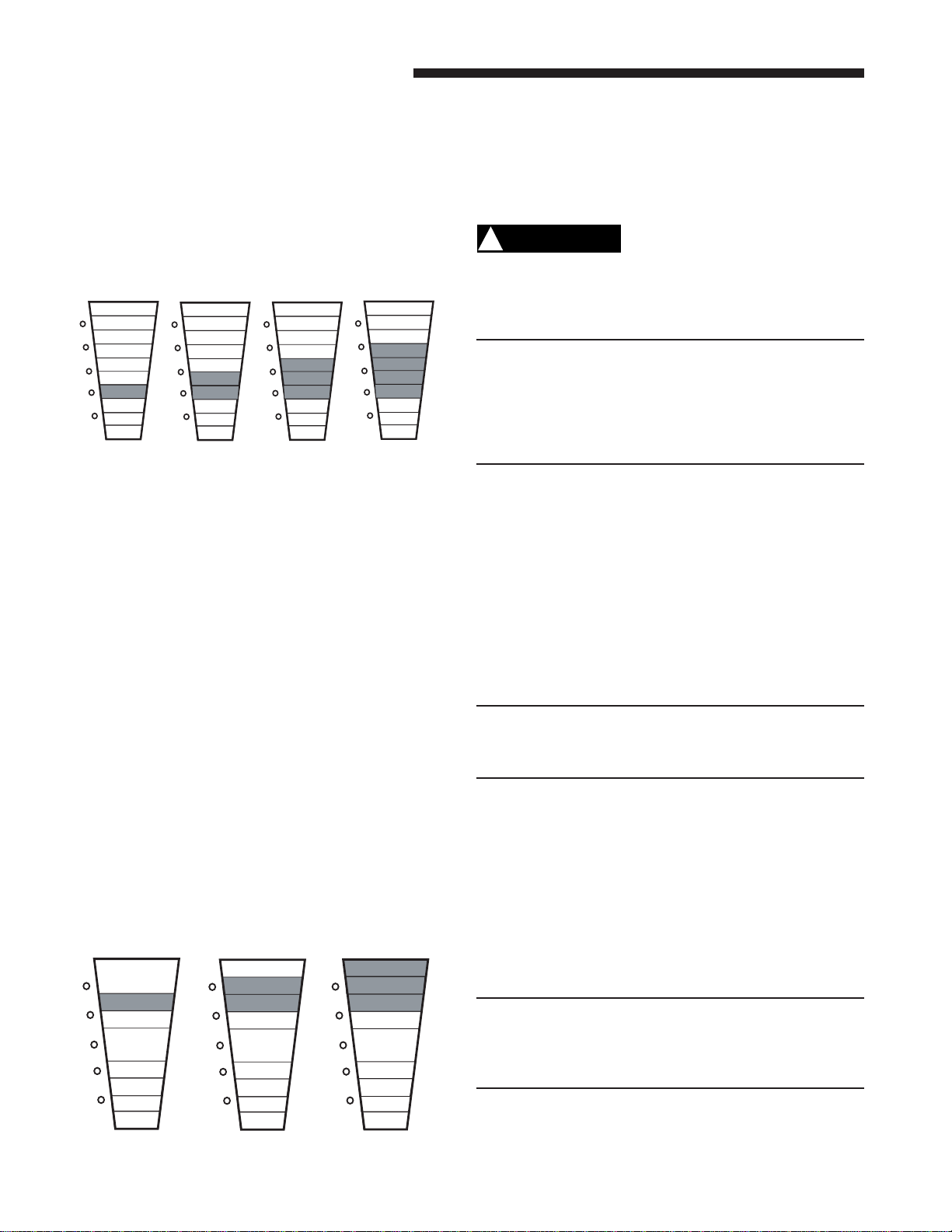
CELL CLEANING SETTING (Fig. 17)
One or more of the YELLOW LED’s will come on indicating
the COLLECTION CELL cleaning time setting. Repeatedly
press the RESET button to cycle through the time options for
the COLLECTION CELLS cleaning cycle until the desired
setting is displayed. Press the POWER button once to accept
that setting and move to the power settings.
Fig. 17 YELLOW LED COLLECTION CELL SETTING
2 Month 4 Months 6 Months* 9 Months
G1
G2
G3
Y3
Y4
R1
R2
R3
Y2
CLEAN
DIRTY
G1
G2
G3
Y3
Y4
R1
R2
R3
Y2
CLEAN
DIRTY
Y1
G1
G2
G3
Y3
Y4
R1
R2
R3
Y2
CLEAN
DIRTY
Y1 Y1
G1
G2
G3
Y3
Y4
R1
R2
R3
Y2
CLEAN
DIRTY
Y1
*Factory Setting
FIELD CHARGER POWER LEVEL
The RED LED lights are used to set the power level of the
FIELD CHARGER for maximum, medium, or minimum. The
number of illuminated RED LED lights indicates the current
setting. The factory setting is for maximum.
Lower settings will reduce the slight sound emitted by the
unit with minimal loss of air cleaning efficiency, if desired.
Lower settings will also further reduce the very low ozone
produced by the air cleaner. The U.S. Food and Drug
Administration recommends indoor ozone concentrations
should not exceed 50 parts per billion. Your air cleaner will
contribute only 5 parts per billion at the factory setting and
can be reduced to 3 parts per billion at the minimum setting.
FIELD CHARGER POWER LEVEL SETTINGS
One or more of the RED LED lights will illuminate. To
change the power level setting, press the RESET button
until the desired setting is indicated.
To save your new settings and exit the Set-Up mode, press
and hold BOTH the POWER and filter RESET buttons for a
minimum of 5 seconds.
Fig. 18 RED LED POWER LEVEL SETTINGS
Minimum Medium Maximum*
G1
G2
G3
Y1
Y3
Y4
R1
R2
R3
Y2
CLEAN
DIRTY
G1
G2
G3
Y1
Y3
Y4
R1
R2
R3
Y2
CLEAN
DIRTY
G1
G2
G3
Y1
Y3
Y4
R1
R2
R3
Y2
CLEAN
DIRTY
*Factory Setting
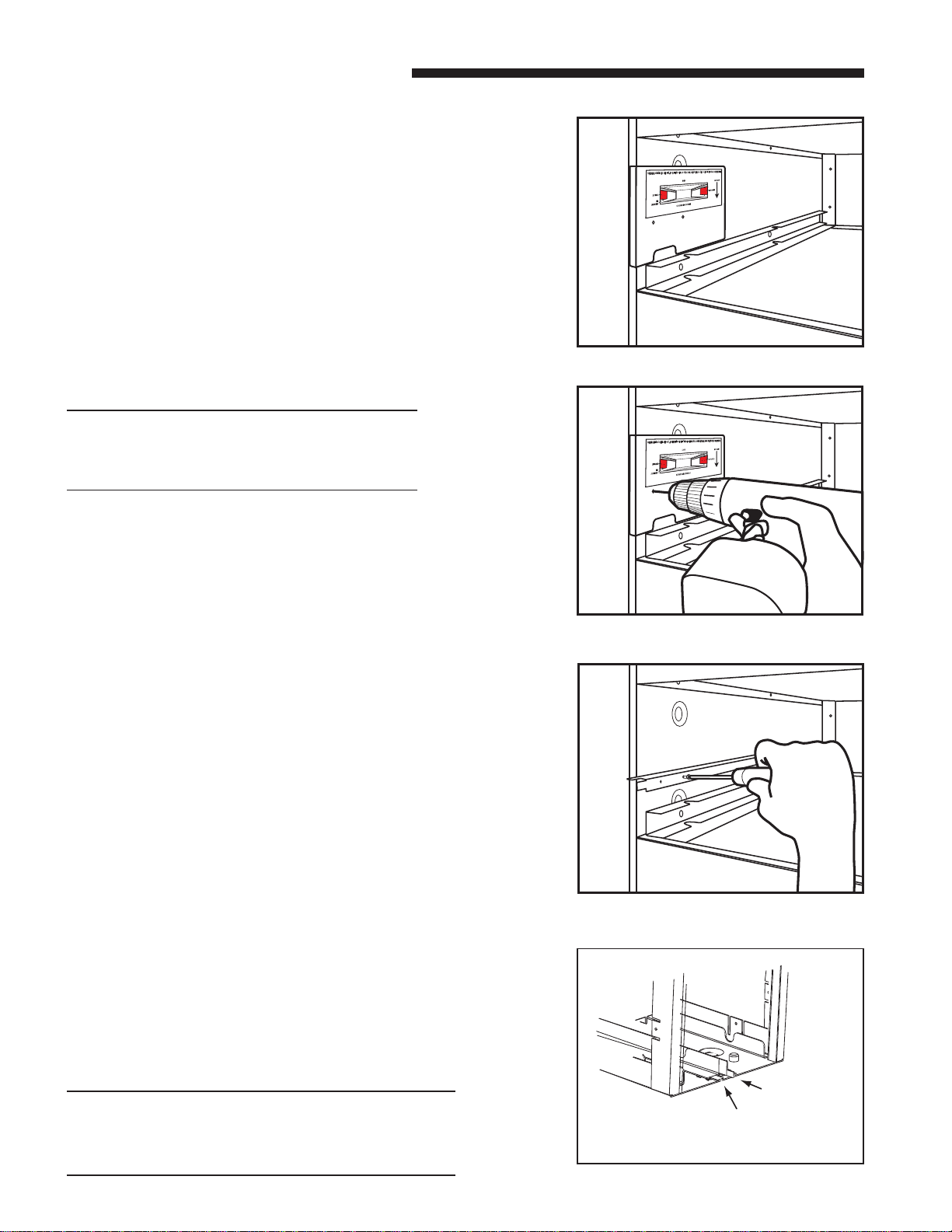
MAINTENANCE
For maximum efficiency the COLLECTION CELLS and PRE-
FILTER should be inspected and cleaned on a regular basis.
The FIELD CHARGER should only be removed and cleaned
annually by an authorized service professional.
CAUTION
!
High Voltage is present within the air cleaner for operation.
Beforeremovingthedoor,turnthepoweroffandwaitatleast
15 seconds to allow voltage to discharge.
NOTE: Before cleaning the coil or ducts in the air handler
or furnace, remove the COLLECTION CELLS, FIELD
CHARGER, and PRE-FILTER from the air cleaner.
Chemicals used during the cleaning of the air handler,
furnace, or ductwork can damage the air cleaner
components and degrade the performance of the air
cleaner.
CLEANING
1. Turn the air conditioning system off at the thermostat.
2. Turn off power to the air cleaner by pushing and holding the
POWERbuttonforthreeseconds. TheLED'swillremainon
until the voltage has discharged and it is safe to remove the
door. This requires approximately 15 seconds. Do not
remove the door until all lights are off.
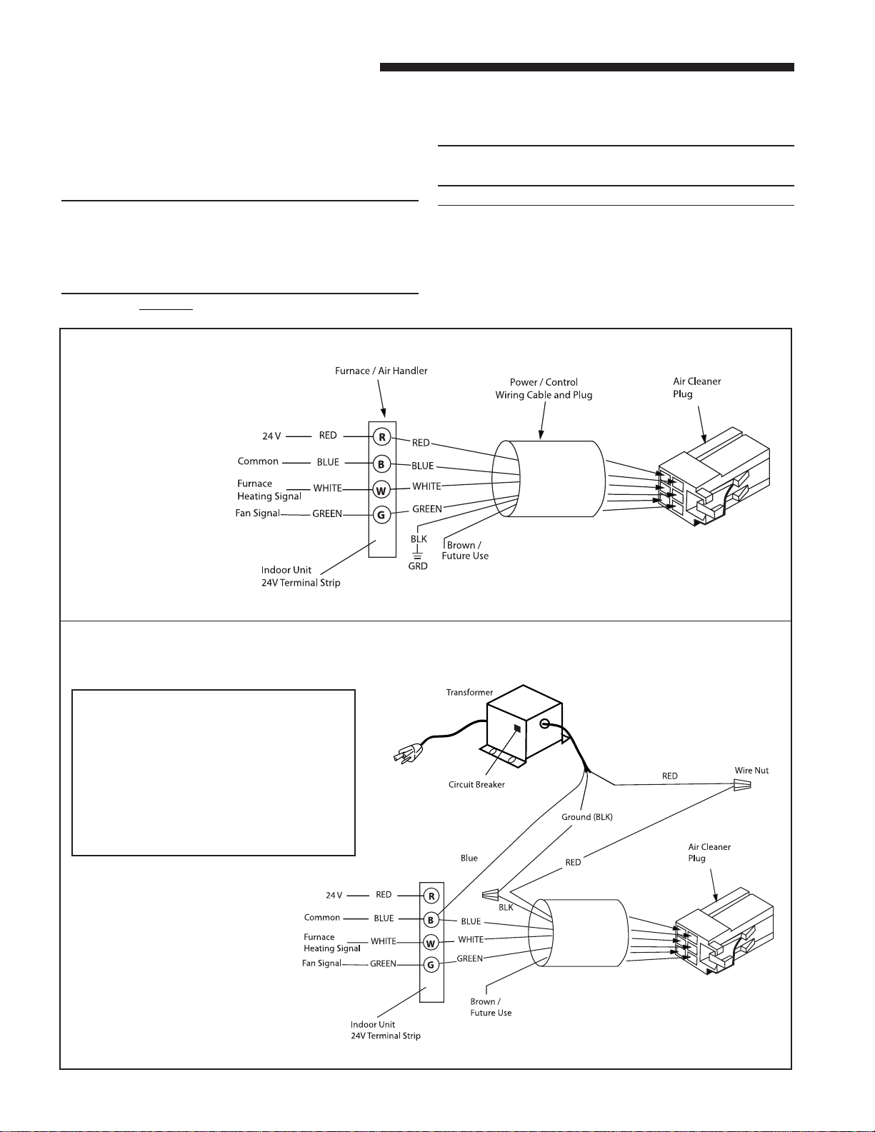
3. Disconnect the power/control cable if required to place the
door in a secure location.
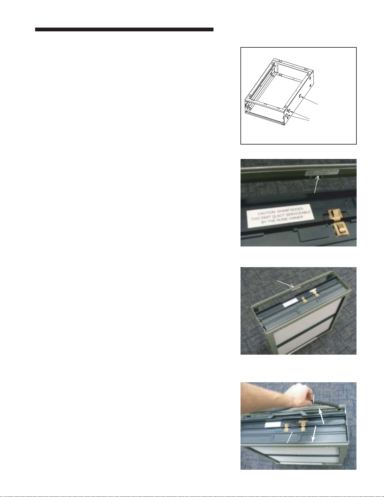
PRE-FILTER CLEANING
The PRE-FILTER can be vacuumed or washed to clean. The
PRE-FILTER should be completely dry before re-installing.
NOTE: Do not replace the plastic PRE-FILTER with a metal
type PRE-FILTER. A metal PRE-FILTER will cause
reduction in efficiency and potential failure of the
electronics in the air cleaner
COLLECTION CELL CLEANING
The COLLECTION CELLS can be cleaned either by
vacuuming (recommended method) or by washing.
VACUUM CLEANING
Vacuum both sides of the COLLECTION CELLS to clean.
WASHING
Use low-pressure water spray, such as a sink sprayer or
garden hose to clean the cells. Some residue may require
warm water to be removed.
• DO NOT USE SOAP OR DETERGENT IN CLEANING THE
COLLECTION CELLS.
• DO NOT IMMERSE THE CELLS COMPLETELY IN WATER.
• DO NOT PLACE THE CELLS INTO A DISHWASHER TO
CLEAN
.
Slightly tap the COLLECTION CELLS to remove water
retained in the filter. Allow the COLLECTION CELLS to dry
before re-installing.