American PRO TIM-615 User manual

INDEX
A. TIM-615: GENERAL OVERVIEW
1) LCD Display
2) User Buttons
3) Measurement Chamber
4) Batteries
B. INSTALLATION
C. DAILY USE
D. CALIBRATION
1) Denitions
2) Reasons to Calibrate
3) Calibration Procedure
4) Display the K Factor & Restoring the
Factory K Factor
5) In-Field Calibration
6) Direct Calibration of the K Factor
E. UNIT OF MEASURE SETUP
F. METER MAINTENANCE
G. TROUBLESHOOTING GUIDE
H. PARTS BREAKDOWN AND SPECIFICATIONS
A. AMERICAN LUBRICATION TIM-615: GENERAL OVERVIEW
TIM-615 is an electronic digital oval-gear meter, designed for precise
measuring of oil and other liquids that are compatible with the
materials found in the meter. The TIM-615 features a non-volatile
memory for storing calibration and dispensing data in the event of
a complete power loss. The meter is unique in that the electronic
section is completely isolated from the uid section. This means that
the electronics can be easily eld replaced while the meter is still
installed in-line using a replacement electronics “head”.
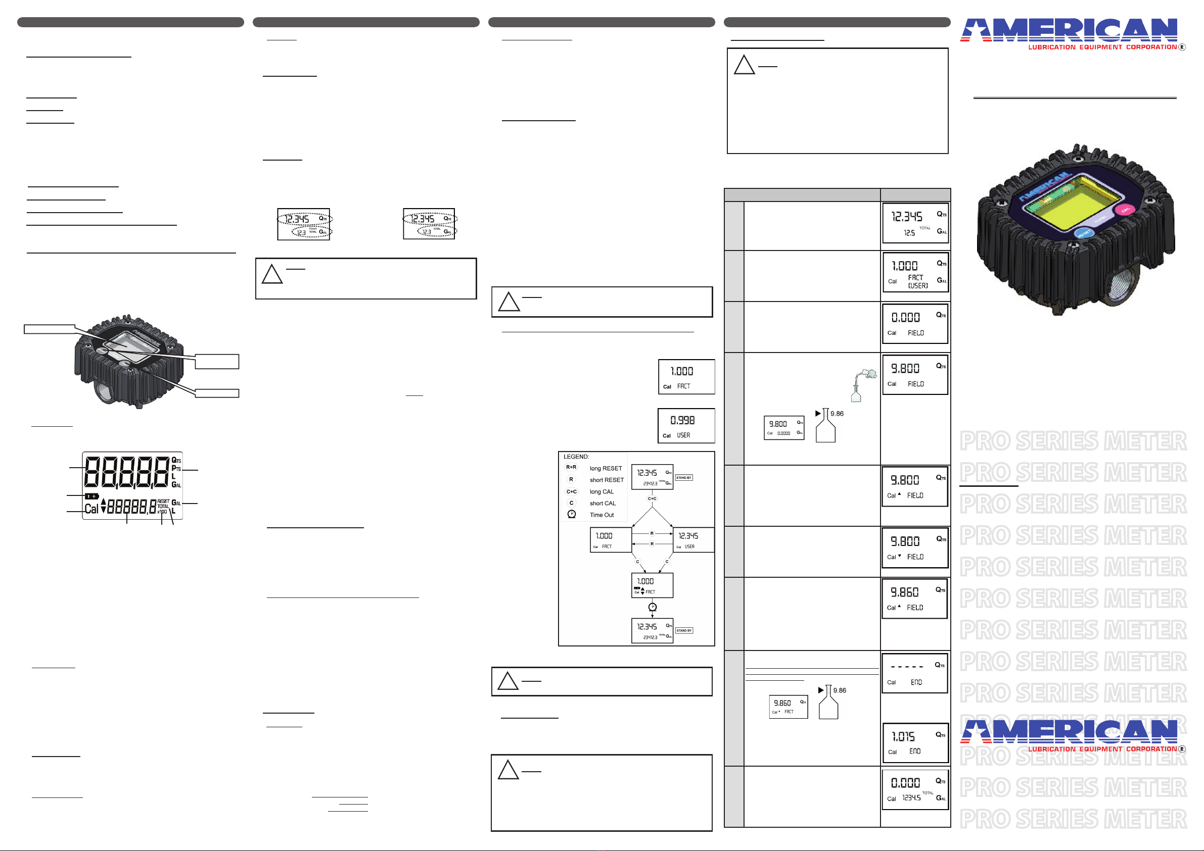
1) LCD Display
The “LCD” of the TIM-615 features two numerical registers and
various symbols that are displayed only when required.
Batch register indicates volume dispensed
Battery charge Indicator
Calibration Mode
Total register; display can show (2) different totals,
one which is resettable and one that is non-
resettable.
Total multiplication factor ( x10 or x100 )
Total type (TOTAL / RESET TOTAL)
Total unit of measurement (Gal=Gallons, L=Liters)
Batch unit of measurement (Qts=Quarts, Pts=Pints,
L=Liters, Gal=Gallons
2) User Buttons
The TIM-615 meter features two buttons (RESET and CAL )
which individually perform two main functions and when pressed
at the same time together perform secondary functions. The
functions are:
For the RESET button, resetting the batch register and the
resettable totalizer.
For the CAL button, entering meter calibration mode.
Pressing RESET and CAL together enters the conguration
mode where the desired unit of measurement can be set.
3) Fluid Chamber
The measurement chamber is located in the lower part of the
meter. It features a 1/2” NPT(F) inlet and outlet. The cover on the
bottom provides access to the chamber for contaminate cleaning.
Inside the chamber are two oval gears that generate electrical
pulses which are counted by the microprocessor. By applying a
calibration factor, the microprocessor translates the pulses into
units of measurement, displayed on the batch and total registers
of the LCD. All TIM-615’s are factory set with a calibration factor
(FACTORY K FACTOR) equal to 1,000.
4 5 6
8
7
1
2
3
2. Reasons to Calibrate
The TIM-615 is supplied with a factory calibration that ensures
precise measuring in most operating conditions. Meter accuracy
might be compromised when dispensing uids like low-viscosity
automatic transmission uid or high-viscosity gear oils. The
meters’ accuracy also might be compromised when operating at
ow rates that are close to the minimum or maximum.
When the meter’s accuracy is less than ideal, user calibration can
be performed to better suit the actual conditions in which the TIM-
615 is required to operate.
3. Calibration Procedure
Two procedures are available for changing the Calibration
Factor:
Dispensing Calibration, performed by means of a dispensing
operation.
Direct Calibration, performed by directly changing the
calibration factor inside the meter.
The calibration phases can be entered (by keeping the CAL button
pressed for a few seconds) to:
Display the current user calibration factor
Return to factory calibration (Factory K Factor) after a previous
calibration by the user
Change the calibration factor using one of the two previously
indicated procedures.
During calibration, the batch and total dispensed quantities
indicated on the display screen take on different meanings
according to the calibration procedure phase.
In calibration mode, the TIM-615 cannot be used for normal
dispensing operations. During the calibration process, the totals
are not increased.
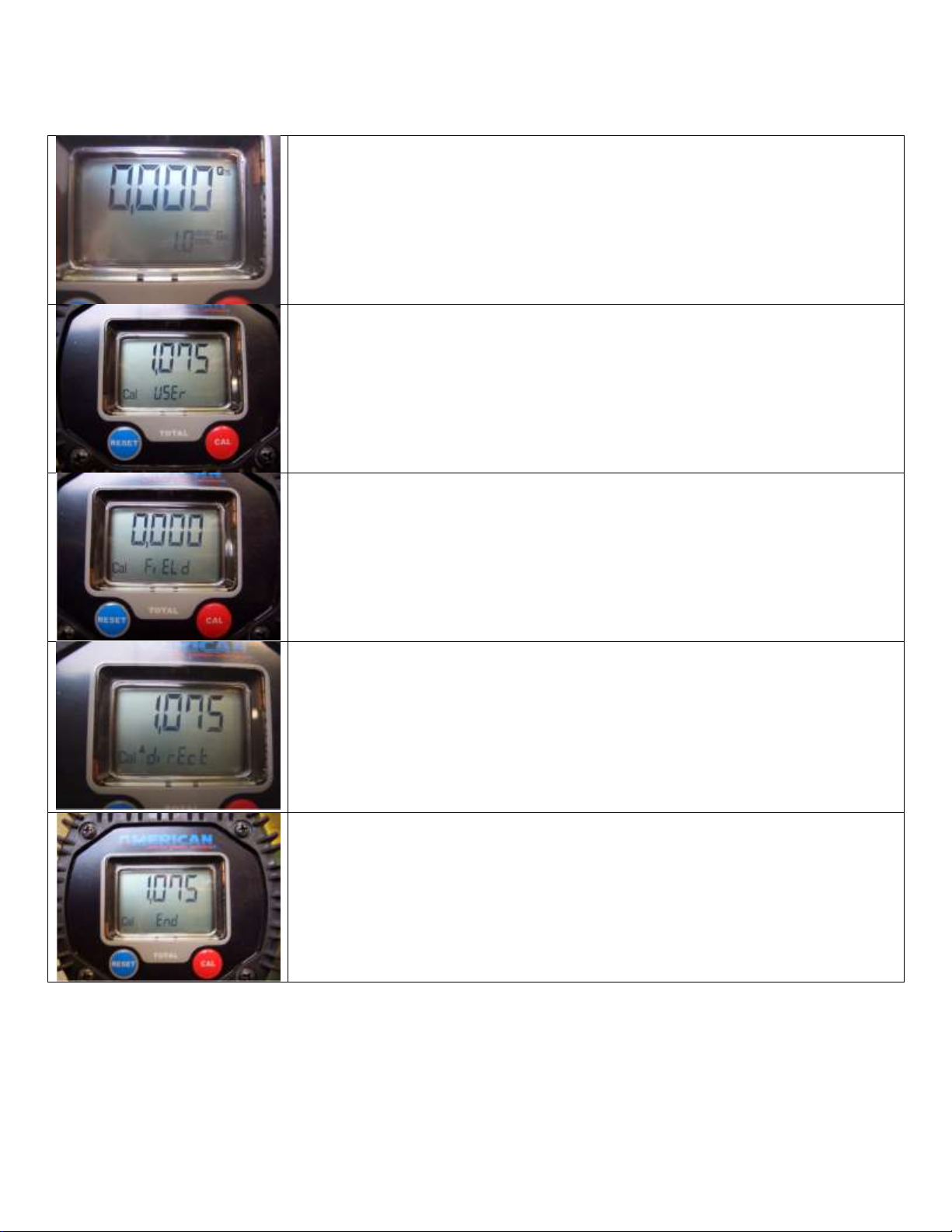
4. Displaying the K Factor & Restoring the Factory K Factor
By pressing the CAL button while the meter is in standby mode,
one of two display pages will appear showing the current
calibration factor.
The following display page will appear if
calibration has been performed or the meter
has been restored to factory calibration.
The word “FACT” (abbreviation for “factory”)
indicates that the factory calibration factor is
being used.
This display page will appear if a calibration
has been made by the user. It shows the
current used calibration factor (in the example
0.998) and the word “USER” (indicating that
the user calibration factor is being used)
The ow chart shows
the switch-over logic
from one display page
to another
In this condition, the
Reset button permits
switching from the
User factor to the
Factory factor.
To conrm the choice
of the calibration
factor, quickly press
the CAL button while
“USER” or “FACT”
are displayed.
After the restart cycle,
the TIM-615 uses
the calibration factor
that had just been
conrmed
5. In-Field Calibration
This procedure requires the uid to be dispensed into a certied
graduated container. For best accuracy, perform this procedure when
the meter is installed in the system it is going to be used on.
5. In-Field Calibration (continued)
ACTION DISPLAY
1Make sure the meter is in standby mode.
If you are unsure, press the REST button and wait 10
seconds.
2Hold down the CAL button until the display reads
“CAL”.
The TIM-615 enters calibration mode, shows <<CAL>> and
displays the calibration factor in use. The words “FACT” and
“USER” indicate which of the two factors (factory or user)
is currently in use.
3Hold down the RESET button until the display reads
“FIELD”.
The TIM-615 shows “CAL” and the batch register set to
zero. The TIM-615 is ready to perform in-eld dispensing
calibration.
4Dispensing into a calibrated container.
Without pressing any buttons, start dispensing
into the graduated container.
Dispensing can be stopped and started again
at will. Continue dispensing until the level of
the uid in the sample container has reached
the graduated area.
Make sure dispensing is correctly nished before performing
the next step.
5Press the RESET button, and quickly release.
This tells the meter that the dispensing is nished. To
nish calibrating the meter, the value on the meter’s batch
display (example 9.800) must be adjusted to equal the
actual amount in the calibrated container. In the bottom left
part of the display an arrow appears (pointing upwards or
downwards), that shows the direction (increase or decrease)
that the value on the batch display will be changed when
performing step 7.
6Changing the Arrows direction in the display
Quickly pressing the RESET button changes the arrows
direction in the display. This operation can be repeated to
alternate the direction of the arrow.
7Adjusting the Batch Display Value (The indicated value
changes in the direction indicated by the arrow)
1) The amount on the display changes one unit each
time the CAL button is pressed quickly.
2) The amount on the display changes continuously
if the CAL button is kept pressed. The speed
of change increases the longer the button is
held.
If you accidentally program the wrong value, repeat the
operation starting from step number 6
8Saving the New Calibration Factor
Before performing this operation, double-check to make
sure the display value on the meter is the same value that is
in the calibrated container.
Press the RESET button for at least one second. The TIM-
615 calculates the new USER K FACTOR. This calculation
could require a few seconds to compute. At the end of the
calculation, the new USER K FACTOR is shown for a few
seconds.
9Finishing
The meter will re-start and enter into the standby mode. The
meter is now programmed with the new calibration factor
and is ready to use.
Note: The calibrated USER K FACTOR is now the factor
used in the TIM-615. This will be the factor the meter will
use even after battery failure and battery replacement.
CAL BUTTON
RESET
BUTTON
LCD DISPLAY
a) For a few seconds after the RESET button is pressed.
b) During the entire dispensing stage and for ve seconds after
dispensing. Once this short time has expired the TIM-615
switches to standby mode and the lower register switches
back to the non-resettable total (TOTAL).
NOTE: 6 digits are available for TOTALS, plus two
icons x 10 / x100. The increment sequence follows: 0.0
→ 99999.9 → 999999 → 100000 x 10 → 999999 x 10 →
100000 x 100 → 999999 x 100
!
!
NOTE: The TIM-615 features a non-volatile memory for
storing calibration and dispensing data. There is no
need to re-calibrate the meter in the event of power loss.
NOTE: When the Factory Factor is chosen, the old user
factor is deleted from the memory
!
1) Completely eliminate all of the air from the system before calibrat-
ing.
2) Use a certied graduated container with a minimum capacity of
5 Qts. Do not use metal or plastic oil containers typically found in
automotive shops. These are typically not accurate enough.
!
NOTE: Important steps for accurate meter calibration:
!
NOTE: Important steps for accurate meter calibration:
(continued)
3) Try to keep the ow rate constant when lling the container. Do
not trickle the ow to reach the desired level (the correct method
during the nal stage is to make short top-offs at the normal
operating ow rate).
4) When oil is dispensed into a container, air gets trapped
inside the oil, making the level in the container appear
higher than it really is. After dispensing, wait a few minutes
to make sure all air bubbles are eliminated from the uid
inside the calibration container.
4) Batteries
The TIM-615 is powered by two standard AAA 1.5V Alkaline
batteries. The batteries can be found under the face of the meter
by removing the four top screws and the protective cover.
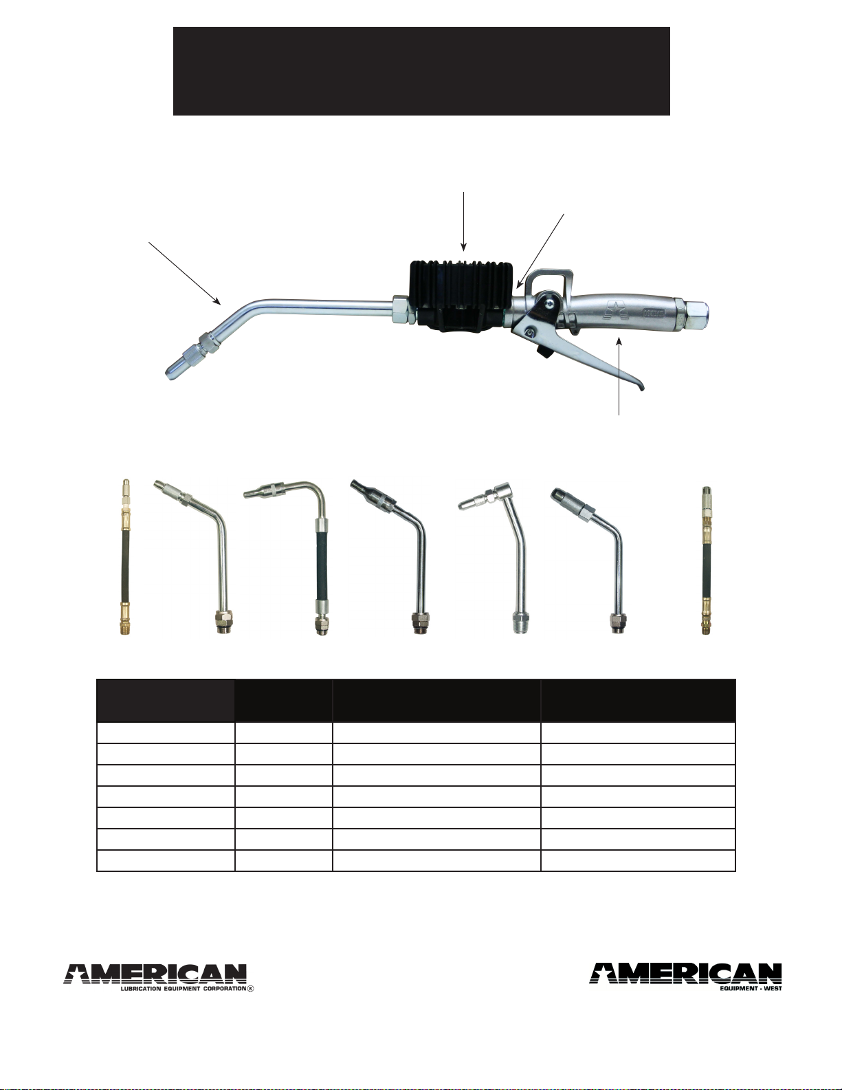
B. INSTALLATION
The TIM-615 features two ½” NPT(F) ports. It has been designed to
be installed in any position, in a xed in-line installation or as part
of a control handle. The meter does not have specic direction of
ow and either port can be used as inlet or an outlet. Make sure
the threaded connections do not interfere with the inside of the
measurement chamber. This can cause the gears to be damaged
and/or seize. A lter with adequate ltering capacity should always
be placed at the inlet of the meter or somewhere in the product
line onto which the TIM-615 is mounted. If solid particles enter the
measurement chamber, the gears could be damaged and/or seize.
C. DAILY USE
Below are the two normal display modes. One display page shows
the batch and resettable total registers (temporary display mode).
The other page shows the batch and non-resettable total register
(standby display mode). Changeover between these two pages
is automatic and tied to phases and times that are factory set and
cannot be changed by the user.
*The batch register is in the top of the display and indicates the
quantity dispensed since the last time the RESET button was
pressed
*The resettable total register (Reset
TOTAL), positioned in the
lower part of the display, indicates the quantity dispensed since
the last time the resettable total was reset. The resettable total
cannot be reset until the batch register has been reset. The unit of
measurement of the two total registers can be the same as the batch
register or a different unit of measure depending on the factory or
user programming choice.
*The non-resettable total register (TOTAL) can never be reset by the
user. It continues to rise for the entire operating life of the TIM-615.
*The register of the two totals (Reset TOTAL and TOTAL) share the
same line of the display. The TIM-615 is programmed to show each
of these totals at different times.
*The non-ressettable (TOTAL) page is shown in standby screen
mode
*The resettable total (Reset TOTAL) page is shown in the temporary
screen mode:
1) Resetting the Batch Register
The batch register can be reset by pressing the RESET button
only when the meter is in standby mode. Press the RESET button
to reset the batch register. After pressing the RESET button, the
LCD screen will display all the characters on the screen, and
then the screen will momentarily go blank. The screen will then
display the resettable total for 5 seconds, after which the display
will return to the standby mode screen.
2) Resetting the Resettable Total (Reset TOTAL)
Wait for the display to enter standby mode
Press the RESET button quickly. This will reset the batch
register.
After pressing the RESET button, the LCD screen will display
all the characters on the screen, and then the screen will
momentarily go blank. The screen will then display the
resettable total for 5 seconds. Hold down the Reset button for
at least one second.
The LCD screen will again display all the characters on the
screen, and then the screen will momentarily go blank. The
screen will then display the resettable total (which now should
read 0.0) for 5 seconds
D. CALIBRATION
1. Denitions
Calibration factor or “K Factor” - this is the multiplication factor
applied by the system to the electrical pulses received, to
transform these into measured uid units.
Factory K Factor: Factory-set default factor. It is equal to
1,000.
The Factory K Factor is based on the following operating
conditions:
User K Factor: Customized calibration factor, meaning the K
Factor obtained from calibrating the meter.
Temporary Display Mode Standby Display Mode
Batch Display Actual Value
Indicated Value Real Value
1)
2)
3)
4)
5)
6)
7)
8)
a)
b)
c)
Fluid 10W30 motor oil
Temperature: 68° F.
Flow rate: 1.3 - 6.6 gallons/min.
a)
b)
c)
d)
a)
b)
c)
a)
b)
a)
b)
c)
PRO SERIES
DIGITAL OVAL GEAR METER
TIM-615
This meter is built exclusively for American
Lubrication Equipment Corporation incorporating
numerous design ideas provided by their design team.
PRO SERIES METER
PRO SERIES METER
PRO SERIES METER
PRO SERIES METER
PRO SERIES METER
PRO SERIES METER
PRO SERIES METER
PRO SERIES METER
PRO SERIES METER
PRO SERIES METER
PRO SERIES METER
PRO SERIES METER
PRO SERIES METER
Baltimore, Md. LosAngeles, Ca.
410-252-9300
americanlube.com
Features
Fluid Isolated from the Electronics
Field-Replaceable Electronic Head
Reliable Oval Gear Design
New AAA Battery Lasts Longer
6 Bolt Construction
Programmable to Pts, Qts, Lts & Gals
Molded-in Shock Guard
Bulletin M0169 EN rev.1
The batch register (top
row) can be reset; the total
register (bottom row)
cannot be reset (even if
you take the batteries
out).

D. CALIBRATION (continued)
6. Direct Calibration of the K Factor
This procedure is useful if the meter is over-dispensing or under-
dispensing uid by a known percentage. Using this method, the
correction of the USER K FACTOR must be calculated by the
operator using the following formula:
New Cal. Factor = Old Cal Factor *
( )
100 - E%
100
Example:
Error percentage found (E%) - 0.3 %
CURRENT calibration factor 1.000
New USER K FACTOR 1.000 * [(100 – ( - 0.3))/100]
= 1.000 * [(100 + 0.9)/100]
= 1.003
If the TIM-615 is under-dispensing (negative error), the new
calibration factor must be higher than the old one as shown in the
example. The opposite applies if the TIM-615 is over-dispensing
(positive error).
ACTION DISPLAY
CONFIGURATION
1Make sure the meter is in standby mode.
If you are unsure, press the REST button and wait 10
seconds.
2Hold down the CAL button until the display reads
“CAL”.
The TIM-615 enters calibration mode, shows <<CAL>>
and displays the calibration factor in use. The words
“FACT” and “USER” indicate which of the two factors
(factory or user) is currently in use.
3Hold down the RESET button until the display reads
“FIELD”.
The TIM-615 shows “CAL” and the batch register set to
zero. The TIM-615 is ready to perform in-eld dispensing
calibration.
4Hold down the RESET button until the display reads
“DIRECT”.
In the bottom left part of the display an arrow appears
(pointing upwards or downwards), that shows the direction
(increase or decrease) that the value on the batch display
will be changed when performing step 6.
5Changing the Arrows direction in the display
Quickly pressing the RESET button changes the arrows
direction in the display. This operation can be repeated to
alternate the direction of the arrow.
6Adjusting the Batch Display Value (The batch display
value changes in the direction indicated by the arrow)
1)The amount on the display changes one unit each
time the CAL button is pressed quickly.
2) The amount on the display changes continuously
if the CAL button is kept pressed. The speed
of change increases the longer the button is
held.
If you accidentally program the wrong value, repeat the
operation starting from step number 5.
7Saving the New Calibration Factor
Before performing this operation, double-check to make
sure the display value on the meter is equal to the value
you obtained using the calibration formula.
Press the RESET button for at least one second. The TIM-
615 calculates the new USER K FACTOR. This calculation
could require a few seconds to compute.
At the end of the calculation, the new USER K FACTOR is
shown for a few seconds.
8Finishing
The meter will re-start and enter into the standby mode.
The meter is now programmed with the new calibration
factor and is ready to use.
Note: The calibrated USER K FACTOR is now the
factor used in the TIM-615. This will be the factor the
meter will use even after battery failure and battery
replacement.
E. UNIT OF MEASURE SETUP
The user can select the batch measurement unit. The choices are:
Quarts (Qts), Pints (Pts), Liters (Lit), and Gallons (Gal). The total
register unit of measurement is automatically determined based on
what is chosen for the batch measurement unit (see chart below).
Combination no. Unit of Measurement
Partial Register
Unit of Measurement
Totals Register
1 Liters (L) Liters (L)
2 Gallons (Gal) Gallons (Gal)
3 Quarts (Qts) Gallons (Gal)
4 Pints (Pts) Gallons (Gal)
E. UNIT OF MEASURE SETUP (continued)
To choose between the 4 available combinations:
Wait for the TIM-615 to go to
Standby.
Press and hold the CAL and RESET
buttons together. Keep these pressed
until the word “UNIT” appears on the
screen. You will also see the current
units of measure (in this example Qts
& Gal).
Each quick press of the RESET
button changes the units of measure.
The chart below shows the order of
scrolling.
Press the CAL key for a few seconds
and the new unit of measurement
will be stored. The meter will re-start
and enter into the standby mode.
The meter is now programmed with
the new unit(s) of measure and is
ready to use.
F. METER MAINTENANCE
The TIM-615 was designed to require minimal maintenance. The
only maintenance required is battery replacement and cleaning the
measuring chamber.
1) Battery Replacement
The TIM-615 is supplied with two SIZE AAA, 1.5 Volt Alkaline
batteries. The meter features two low-battery alarm warnings:
When the battery charge falls
below the rst level, the xed battery
symbol appears on the LCD. In
this condition, the meter continues
to operate correctly, but the xed
battery icon warns the user that it is
time to change the batteries.
If you continue to use the meter
without changing the batteries
the second battery alarm level will
eventually be reached, preventing
meter operation. In this condition
the battery icon will ash and will
be the only item visible on the LCD.
You must change the batteries once
the meter has reached this mode.
All dispensing data from this point
forward will not be displayed or
stored in the meter.
To change the batteries, refer to the spare parts list
in the next column while completing the following
steps:
Press reset to update all the totals.
Remove the 4 screws on the cover (item 5).
Remove the cover (item 8).
Replace the two dead batteries (item 9).
Put the cover on and re-tighten the 4 cover screws,
making sure that it has been positioned correctly.
The meter will switch on automatically and enter
into the standby mode. It is now ready to resume
normal operation.
After changing the batteries, the meter will display
the same reset total, the same non-ressettable
total and the same batch total as it did before the
batteries were changed. The meter will also use the
same calibration factor as it did before the power
outage/battery replacement.
2) Cleaning
The measuring chamber of the TIM-615 can be cleaned without
removing the unit from the dispensing nozzle or the line on which
it is installed.
To clean debris from the measuring chamber, refer to the spare
parts list on the right while completing the following steps:
Loosen the six retention screws (item 7) on the
body (item 1).
Remove the cover (item 2) and the seal (item 10)
Remove the two oval gears (item 13).
Clean where necessary. For this operation, use a
brush or pointed object such as a small screwdriver.
Be careful not to damage the body or the gears.
To reassemble the unit, carry out these steps in
the reverse order. Please pay close attention to the
note below before re-assembling the meter!
G. TROUBLESHOOTING GUIDE
Problem Possible cause Remedial Action
Dull LCD Low Battery Replace the batteries
(see section F.)
Inaccurate
Dispensing
Wrong K FACTOR Re-calibrate
(see section D.)
Reduced or Zero
Flow Rate
Gears blocked Clean the measurement
chamber (see section F.)
The meter does
not count, but
the ow rate is
correct
Incorrect installation of
gears after cleaning
Repeat the reassembly
procedure
(see section F.)
Possible circuit board
problem
Contact your local
American Lubrication
Equipment dealer
H. PARTS BREAKDOWN & SPECIFICATIONS
Item Part Number Description Qty
1 TIM-615-1 Fluid Chamber Body 1
2 TIM-615-2 Isolation Plate 1
3 TIM-615-3 Battery Support Tray 1
4 TIM-615-4 Circuit Board 1
5 TIM-615-5 Cover Screw 4
6 TIM-615-6 Circuit Board Screw 4
7 TIM-615-7 Fluid Body Screw 6
8 TIM-615-8 Protective Cover 1
9 TIM-615-9 AAA Battery 2
10 TIM-615-10 Gasket 1
11 TIM-615-11 Cover label 1
12 TIM-615-12 Adhesive Strip 2
13 TIM-615-13 Magnetic Gear 1
14 TIM-615-14 Non-Magnetic Gear 1
15 TIM-615-15 Gear Post 2
16 TIM-615-HEAD
Replacement Meter
Head includes items 2,
3, 4, 5, 6, 8 , 9, 11 & 12
1
H. PARTS BREAKDOWN & SPECIFICATIONS (continued)
Measurement
system
Oval Gear
Resolution (nominal) 0.005 (Quarts/Pulse)
Flow Rate (Range) 1-26 (Quarts/Minute)
Operating pressure (Max) 1000 (PSI)
Bursting pressure (Min) 2000 (PSI)
Storage temperature (Range) -5 to 158 (°F)
Storage humidity (Max) 95 (% RH)
Operating
temperature
(Max) 140 (°F)
Flow resistance (at 16 quarts/min with
SAE10W motor oil at 68°F)
19 (PSI)
Viscosity (Range) 5÷5000 (mPas)
Precision (1 and 26 quarts/min) ±1 of value indicated after
calibration (%)
Repeatability (Typical) ±0.3 (%)
Screen Liquid crystals LCD
Featuring:
- 5-gure partial
- 6-gure Reset Total plus x10 / x100
- 6-gure non reset Total plus x10 / x100
Power supply (2) 1.5 V alkaline batteries size AAA
Battery life 14,000 - 100,000 hours
Weight .83 lbs. (including batteries)
NOTE: The Reset Total and Total will be automatically
converted to the new unit of measurement. No
new calibration is required when changing the
unit of measurement.
!
b)
a)
NOTE: Refer to your local regulations before disposing the old
batteries.
!
1)
2)
3)
4)
c)
NOTE: Always make sure the liquid has been drained
from the meter before cleaning.
!
NOTE: Only one of the two gears has magnets.These
gears must be inserted into the body of the meter, and
placed perpendicular to each other. To position the gears
correctly, refer to the diagram below, making sure that
the position of the gear with respect to the magnets is
observed. If the gears are not installed correctly, the me-
ter will not work. Check that the gears are rotating freely
before closing the cover.
!
1)
2)
3)
4)
5)
6)
1)
2)
3)
4)
5)
4-1/4”
2.46”
3/4”
2.38”
2.54”
1/2" NPT
3.21”
2.55”
3.57”
11
5
8
9
6
4
3
12
2
10
13
15
1
7
14
16
d)
!
NOTE: The gear with the magnet (TIM-615-13) must be pla-
ced so that it is on the left side of the meter when assmbled

In Field Calibration Procedures for the TIM-600 Series Digital Meter
Note: Due to various grades of oil and temperatures, every meter should be individually calibrated when installed.
Purge the system of air by dispensing fluid until the flow is full and steady. Use an
accurate measuring container not less than 5 quarts. A glass beaker will give the
most accurate reading.
During calibration dispense at the same flow used in normal dispensing.
Do not “choke” or “trickle” the flow to reach the exact volume. The correct
technique is to stop and start at full flow as many times as needed to reach the
exact value in the container.
Firmly press and release the blue RESET Button. Wait about 10 seconds. The
word “reset” will disappear. This will zero out the reading.
Press and hold the red CAL button.
If this is the first time for calibration it will read CAL-FACT.
If calibration has been done before it will read CAL-USER.
Press and hold the RESET button until the display changes to “0.000” and the
letters CAL FIELD appear.
Dispense 4 quarts of oil into your container. Start and stop the flow as needed to
reach the appropriate level in the container.
Press and hold the RESET button until an arrow appears in the lower left hand
corner of the display. It will read CAL Direct with an arrow pointing up. If the total
is under 4 quarts use this setting.
If the total is over 4 quarts press and release the RESET button to get the arrow to
point down.
The CAL button will move it in the direction you’ve chosen.
Press and hold the CAL button until the display reads “4.000” then release the
button.
Press and hold the RESET button until CAL END appears. It will then show the
new CAL setting which will be stored in the memory. After a few seconds the
meter will change back to normal operation mode. The calibration process is now
complete and the meter is ready to dispense product.
Unit of Measure
The TIM-615 meter features a menu which allows the user to change the unit of measure: quarts (Qts), pints (Pts), liters
(L) and gallons (Gal). Please note that the gallons ‘odometer’, in the lower right hand corner, is not resettable.
1. Push and hold both the Reset and the Cal. Buttons.
2. Meter should display: “UNIT”

3. Using the reset button, choose the desired unit (quarts/pints/liters/gallons)
4. Push and hold the Cal. Button to activate the selected unit of measure.
Replacing a Metered Control Handle.
1. Shut off the air supply to the oil pump at the bulk oil storage tank.
2. Go to the control handle that needs to be replaced. Take a bucket with you.
3. Open the manual non-drip tip (if supplied with one) on the control handle. Squeeze the control handle trigger
and drain the oil from the hose into the bucket. This removes pressure from the product hose.
4. Remove the control handle from the hose, using two crescent wrenches.
5. Drain the oil from the hose and the control handle into the bucket.
6. Remove any residual tape or sealant from the hose threads. Put two wraps of Teflon tape on the hose threads.
7. Install and tighten the replacement control handle on the threads of the hose using two crescent wrenches.
8. DO NOT over tighten the control handle to the hose or you could damage the swivel.
9. Leave the bucket at the control handle. Return to the oil pump. Sair to the pump.
10. You will hear the pump cycle for a short time as it replaces the oil that you drained from the hose.
11. Return to the control handle and pull the trigger to purge any air from your hose into the bucket.
12. When you have a steady flow of oil coming out, stop dispensing and close the non-drip tip on the control handle.
13. Dispose of the oil in the bucket into your waste drain.
Trouble Shooting Control Handles
There is a display problem?
oHave you changed the batteries?
The meter is dispensing oil but not metering anything?
oHave you changed the batteries?
Meter not dispensing any product?
oIs the non-drip tip open?
Meter leaking out of the tip on to the floor?
oIf it is an automatic tip, change to a manual non-drip tip.
oIf it is a manual tip, are the techs wiping the tip with a rag and closing the tip after each use.
Product is being dispensed slowly?
oIf it is a manual tip make sure the non-drip tip is fully open.
oCheck air regulator setting: Should be at least 50 PSI for a 5:1 pump and 75 PSI for a 3:1 pump.
Not metering accurately?
oCheck air regulator setting: reduce to 50 PSI for a 5:1 pump and 75 PSI for a 3:1 pump.
oIf the air pressure is set too high you will over pressurize the lines and the meter may not read accurately.
Have you changed the calibration setting?
oRecalibrate the meter.
Meter leaking at the swivel?
oReplace the control handle
Oil leaking around the meter?
oReplace the control handle
Meter leaking oil out of the handle?
oReplace the control handle
Note: TIM-615 meters can be reversed. The meters are non-directional.

Tip Assembly
(see chart)
TIM-600 Pro Series Digital Control
Handle Parts Breakdown Chart
TIM-615
(meter)
TIM-1207
(nipple)
TIM-744
(1/2” swivel)
TIM-740-TG
(handle, swivel not included)
1251 North Patt Street
11212AMcCormick Road
Hunt Valley, MD 21031 Anaheim, CA 92801
Phone: (410) 252-9300
www.americanlube.com Form: TIM-600-PART
Model
Number
Tip
Style Description Tip
Assembly
TIM-600-FA 3* Flex Automatic TIM-747
TIM-600-FM 1 Flex Manual TIM-743
TIM-600-RMGO 5 Swivel 90º Rigid Manual TIM-742
TIM-600-FMHF 7 Flex Manual Hi-Flow TIM-743-1
TIM-600-RA 4* Rigid Automatic TIM-746
TIM-600-RM 2* Rigid Manual TIM-753
TIM-600-RMHF 6* Rigid Manual Hi-Flow TIM-752
*These tip assemblies have had their compression nuts "Loctited" at the factory during the assembly process. We recommend placing a few drops
of Loctite® 680 Retaining Compound on the threads of the compression nut when replacing these tip assemblies. This will assure that the compres-
sion nuts do not come loose during normal use. Do not, under any circumstances, place Loctite ® on the threads that are used to fasten the
tip assembly to the meter body.
1 2* 3* 4* 5 6* 7
Date: Feb 2017
Version: 1.02

Tip Assembly
(see chart)
TIM-601 Pro Series Digital Control
Handle Parts Breakdown Chart
Y-27-54C
(nipple)
TIM-741
(handle with swivel)
1251 North Patt Street
11212AMcCormick Road
Hunt Valley, MD 21031 Anaheim, CA 92801
Phone: (410) 252-9300
www.americanlube.com
*These tip assemblies have had their compression nuts "Loctited" at the factory during the assembly process. We recommend placing a few drops
of Loctite® 680 Retaining Compound on the threads of the compression nut when replacing these tip assemblies. This will assure that the compres-
sion nuts do not come loose during normal use. Do not, under any circumstances, place Loctite ® on the threads that are used to fasten the
tip assembly to the meter body.
*Filter cleaning procedure: (1) remove swivel, (2) remove/clean/reinstall filter, (3) reinstall swivel
Model
Number
Tip
Style Description Tip
Assembly
TIM-601-FA 3* Flex Automatic TIM-747
TIM-601-FM 1 Flex Manual TIM-743
TIM-601-RMGO 5 Swivel 90º Rigid Manual TIM-742
TIM-601-FMHF 7 Flex Manual Hi-Flow TIM-743-1
TIM-601-RA 4* Rigid Automatic TIM-746
TIM-601-RM 2* Rigid Manual TIM-753
TIM-601-RMHF 6* Rigid Manual Hi-Flow TIM-752
1 2* 3* 4* 5 6* 7
Form: TIM-601-PART
Date: Feb 2017
Version: 1.02
TIM-615
(meter)
Note: If you have the
prior, black, version of
the guardless handle,
use swivel part number:
TIM-740-SWIV

The picture below is of a TIM-715 which is obsolete. The TIM-715 uses alkaline, type N
batteries [Dia. 0.44” by 1.17” or 1-3/16”]. If the meter won’t count or you get “ERR-1,” the
meter is not repairable.
The TIM-715 meter can be replaced with a new TIM-615 meter. You can reuse your old
extension/nozzle and old control handle with the TIM-615.
Please call 410-252-9300 and press 3 for pricing and availability.
The upper of numbers reset to zero after a battery replacement and should count up as oil is
pumped through the meter. The number in the lower right corner is not resettable.
Table of contents
Other American Measuring Instrument manuals