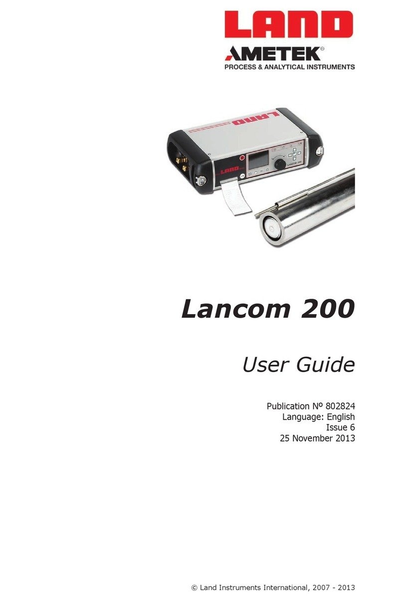
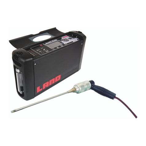
Ametek Land 4500 MKIII User manual

Model 4500 MkIII
i
4500 MKIII
USER GUIDE
PUBLICATION NO804546
LANGUAGE: ENGLISH
QUALITY CUSTOMER SOLUTIONS

Health and Safety Information
Read all of the instructions in this booklet - including all the WARNINGS and CAUTIONS
- before using this product. If there is any instruction which you do not understand, DO
NOT USE THE PRODUCT.
Safety Signs
WARNING
Indicates a potentially hazardous situation which, if not avoided, could result in death or
personal injury.
CAUTION
Indicates a potentially hazardous situation which, if not avoided, could result in minor or
moderate injury to the user or users, or result in damage to the product or to property.
NOTE
Indicates a potentially hazardous situation which, if not avoided, could result in damage or the loss of
data.
Signs and Symbols used on equipment and Documentation
Caution, risk of electric shock.
Caution, attention to possibility of risk of damage to the product, process or surroundings. Refer
to instruction manual.
Caution, hot surface.
Protective Conductor Terminal.
Observe precautions for handling electrostatic discharge sensitive devices.
Equipment Operation
Use of this instrument in a manner not specied by Land Instruments International may be hazardous.
Read and understand the user documentation supplied before installing and operating the equipment.
The safety of any system incorporating this equipment is the responsibility of the assembler.
Protective Clothing, Face and Eye Protection
It is possible that this equipment is to be installed on, or near to, machinery or equipment operating at
high temperatures and high pressures. Suitable protective clothing, along with face and eye protection
must be worn. Refer to the health and safety guidelines for the machinery/equipment before installing
this product. If in doubt, contact Land Instruments International.
Electrical Power Supply
Before working on the electrical connections, all of the electrical power lines to the equipment must
be isolated. All the electrical cables and signal cables must be connected exactly as indicated in these
operating instructions. If in doubt, contact Land Instruments International.
Storage
The instrument should be stored in its packaging, in a dry sheltered area.
Unpacking
Check all packages for external signs of damage. Check the contents against the packing note.
Lifting Instructions
Where items are too heavy to be lifted manually, use suitably rated lifting equipment. Refer to the
Technical Specication for weights. All lifting should be done as stated in local regulations.
IMPORTANT INFORMATION - PLEASE READ
Contact Us
UK - Droneld
Land Instruments International
Tel: +44 (0) 1246 417691
Web: www.landinst.com
USA - Pittsburgh
AMETEK Land, Inc.
Tel: +1 412 826 4444
Web: www.ametek-land.com
China
AMETEK Land China Service
Tel: +86 21 5868 5111 ext 122
Email: land.enquiry@ametek.com
Web: www.landinst.com
India
AMETEK Land India Service
Tel: +91 - 80 67823240
Web: www.landinst.com
For further details on all AMETEK Land oces, distributors and representatives, please visit
our websites.
Return of Damaged Goods
IMPORTANT If any item has been damaged in transit, this should be reported to the carrier and to the
supplier immediately. Damage caused in transit is the responsibility of the carrier not the supplier.
DO NOT RETURN a damaged instrument to the sender as the carrier will not then consider a claim. Save
the packing with the damaged article for inspection by the carrier.
Return of Goods for Repair
If you need to return goods for repair please contact our Customer Service Department. They will be able
to advise you on the correct returns procedure.
Any item returned to Land Instruments International should be adequately packaged to prevent damage
during transit.
You must include a written report of the problem together with your own name and contact information,
address, telephone number, email address etc.
Design and Manufacturing Standards
The Quality Management System of Land Instruments International is approved to BS EN ISO 9001 for
the design, manufacture and on-site servicing of combustion, environmental monitoring and non-contact
temperature measuring instrumentation.
Registered ISO9001 Management System approvals apply in the USA
UK Calibration Laboratory: UKAS 0034
USA Calibration Laboratory: ANAB Accredited ISO/IEC 17025
National Accreditation Board for Testing and Calibration Laboratories approvals apply in India.
Operation of radio transmitters, telephones or other electrical/electronic devices in close proximity
to the equipment while the enclosure doors of the instrument or its peripherals are open, may cause
interference and possible failure where the radiated emissions exceed the EMC directive.
The protection provided by this product may be invalidated if alterations or additions are made to the
structural, electrical, mechanical or pneumatic parts of this system. Such changes may also invalidate the
standard terms of warranty.
Copyright
This manual is provided as an aid to owners of Land Instruments International’s products and contains
information proprietary to Land Instruments International. This manual may not, in whole or part, be
copied, or reproduced without the expressed written consent of Land Instruments International Ltd.
Copyright © 2017 Land Instruments International.
MARCOM0311, Issue 8, 07 September 2017


Health and Safety Information
Read all of the instructions in this booklet - including all the WARNINGS and CAUTIONS
- before using this product. If there is any instruction which you do not understand, DO
NOT USE THE PRODUCT.
Safety Signs
WARNING
Indicates a potentially hazardous situation which, if not avoided, could result in death or
personal injury.
CAUTION
Indicates a potentially hazardous situation which, if not avoided, could result in minor or
moderate injury to the user or users, or result in damage to the product or to property.
NOTE
Indicates a potentially hazardous situation which, if not avoided, could result in damage or the loss of
data.
Signs and Symbols used on equipment and Documentation
Caution, risk of electric shock.
Caution, attention to possibility of risk of damage to the product, process or surroundings. Refer
to instruction manual.
Caution, hot surface.
Protective Conductor Terminal.
Observe precautions for handling electrostatic discharge sensitive devices.
Equipment Operation
Use of this instrument in a manner not specied by Land Instruments International may be hazardous.
Read and understand the user documentation supplied before installing and operating the equipment.
The safety of any system incorporating this equipment is the responsibility of the assembler.
Protective Clothing, Face and Eye Protection
It is possible that this equipment is to be installed on, or near to, machinery or equipment operating at
high temperatures and high pressures. Suitable protective clothing, along with face and eye protection
must be worn. Refer to the health and safety guidelines for the machinery/equipment before installing
this product. If in doubt, contact Land Instruments International.
Electrical Power Supply
Before working on the electrical connections, all of the electrical power lines to the equipment must
be isolated. All the electrical cables and signal cables must be connected exactly as indicated in these
operating instructions. If in doubt, contact Land Instruments International.
Storage
The instrument should be stored in its packaging, in a dry sheltered area.
Unpacking
Check all packages for external signs of damage. Check the contents against the packing note.
Lifting Instructions
Where items are too heavy to be lifted manually, use suitably rated lifting equipment. Refer to the
Technical Specication for weights. All lifting should be done as stated in local regulations.
IMPORTANT INFORMATION - PLEASE READ
Contact Us
UK - Droneld
Land Instruments International
Tel: +44 (0) 1246 417691
Email: [email protected]
Web: www.landinst.com
USA - Pittsburgh
AMETEK Land, Inc.
Tel: +1 412 826 4444
Web: www.ametek-land.com
China
AMETEK Land China Service
Tel: +86 21 5868 5111 ext 122
Email: [email protected]
Web: www.landinst.com
India
AMETEK Land India Service
Tel: +91 - 80 67823240
Email: [email protected]
Web: www.landinst.com
For further details on all AMETEK Land oces, distributors and representatives, please visit
our websites.
Return of Damaged Goods
IMPORTANT If any item has been damaged in transit, this should be reported to the carrier and to the
supplier immediately. Damage caused in transit is the responsibility of the carrier not the supplier.
DO NOT RETURN a damaged instrument to the sender as the carrier will not then consider a claim. Save
the packing with the damaged article for inspection by the carrier.
Return of Goods for Repair
If you need to return goods for repair please contact our Customer Service Department. They will be able
to advise you on the correct returns procedure.
Any item returned to Land Instruments International should be adequately packaged to prevent damage
during transit.
You must include a written report of the problem together with your own name and contact information,
address, telephone number, email address etc.
Design and Manufacturing Standards
The Quality Management System of Land Instruments International is approved to BS EN ISO 9001 for
the design, manufacture and on-site servicing of combustion, environmental monitoring and non-contact
temperature measuring instrumentation.
Registered ISO9001 Management System approvals apply in the USA
UK Calibration Laboratory: UKAS 0034
USA Calibration Laboratory: ANAB Accredited ISO/IEC 17025
National Accreditation Board for Testing and Calibration Laboratories approvals apply in India.
Operation of radio transmitters, telephones or other electrical/electronic devices in close proximity
to the equipment while the enclosure doors of the instrument or its peripherals are open, may cause
interference and possible failure where the radiated emissions exceed the EMC directive.
The protection provided by this product may be invalidated if alterations or additions are made to the
structural, electrical, mechanical or pneumatic parts of this system. Such changes may also invalidate the
standard terms of warranty.
Copyright
This manual is provided as an aid to owners of Land Instruments International’s products and contains
information proprietary to Land Instruments International. This manual may not, in whole or part, be
copied, or reproduced without the expressed written consent of Land Instruments International Ltd.
Copyright © 2017 Land Instruments International.
MARCOM0311, Issue 8, 07 September 2017

Opacity and Dust Monitor
User Guide
Model 4500 MkIII
Preface
Blank

Preface
Model 4500 MkIIIOpacity and Dust Monitor
User Guide
Contents
A Introduction A-1
A1 General Description A-1
A2 Installation Diagram A-3
A3 Installation Instructions A-4
A4 AFU-APS-I/O Auxiliary Function Unit A-22
A5 AFU-APS-I/O: Process I/O Board A-29
A6 AFU-APS-I/O: Auxiliary Power Supply (APS) A-32
B Getting Started B-1
B1 The User Interface B-1
B2 Function Keys B-2
B3 Glossary of Terms B-5
B4 Using the Instrument for the First Time B-6
B5 Periodic Modes of Operation B-20
C Theory of Operation and Application C-1
C1 General Outline C-1
C2 Beer-Lambert’s Law C-2
C3 Pathlength Correction Factor (PLCF) C-3
C4 ExamplesofDierentPathlengthCorrectionFactors(PLCF) C-5
C5 Requirements for Environmental Legislation C-6
C6 Physical Principles C-7
D SystemSpecication D-1
D1 4500 MkIII Dust and Opacity Monitor D-1
D2 Auxiliary Functions Unit & Auxiliary Power Supply (AFU & APS) D-3
E Maintenance E-1
E1 Identifying Faults E-1
E2 Routine Maintenance E-3
E3 Locking the Fail-Safe Shutter Open E-4
E3 Upgrading the 4500 MkIII Transceiver Firmware E-5
E4 Replacement Parts and Consumables E-13
F Changing the Installation Pathlength on a Model 4500 MkIII F-1
F1 Set the correct focus F-1
F2 Align and Calibrate the Model 4500 MkIII F-1
F3 Set the B constant F-1
F4 Calibration Error Test F-2
F5 Focus Table F-3
F6 Sequence Numbers for Grating and Aperture Combinations F-4
G Instrument Record Sheets G-1
G1 CongurationRecordSheet G-1
G2 Model 4500 MkIII Parameter Record Sheet G-2
H Optional I/O Modules for the AFU H-1
H1 Ethernet Module (804651) H-1
Appendix 1 Long Pathlength Option

INTRODUCTION
A

A - 1
Model 4500 MkIIIOpacity and Dust Monitor
User Guide
AIntroduction
A1 General Description
The Land Instruments International Model 4500 MkIII Continuous Opacity
Monitoring System (COMS) measures opacity by shining a light beam
throughuegases.
Aninternalmicroprocessorcalculatesdustdensityandotherparameters.
The Model 4500 MkIII is designed for continuous operation in all weather
conditions.Maintenancerequirementsareminimal.
Transceiver Containing all of the major electronic and electro–optic
components.
Retro-Reector Containingacornercubereector.
Air Purge System A continuous supply of purge air is essential to prevent
dustandcorrosivegasesfromaectingtheoptical
system.Singleanddualelectricblowersorcompressed-
air driven devices are available to suit individual site
requirements.Automaticfail–safeshutterscanalsobe
ttedfortemporaryprotectionintheeventofapurgeair
failure.

Opacity and Dust Monitor
User Guide
Model 4500 MkIII
A - 2
Power Supply
The model 4500 MkIII operates from a 24 V d.c. supply.
Analogue Output
The Model 4500 MkIII Dust and Opacity Monitor has a current loop output
that may be set to one of the four functions below:
Opacity Dust
Constant Current Optical Density
The output can be set to ‘TRACK’ or ‘HOLD’ the measurement signal during
calibrationroutines.If‘TRACK’isset,themeasurementsignalwillcontinue
tobeoutputduringcalibration.If‘HOLD’isset,themeasurementsignalwill
remainatthelastrecordedreadingbeforecalibration,untilthecalibration
routineiscomplete.
Relay Outputs
Located on the key panel of the 4500 MkIII are three LEDs which light to
indicate the operation of the following relay outputs:
SYSTEM OK
CALIBRATION
ALARMS
Computer Interface Operation
The Model 4500 MkIII Dust and Opacity Monitor may be connected to a
computerordataacquisitionsystemviaitsRS485Modbusinterface.
Auxiliary Function Unit and Power Supply (AFU-APS-I/O 4500 MkIII)
Optionalexternalconnectionboxwhichoersscrewterminalconnections
plusenhancedinput/outputoptions,andanexternalmains-poweredunit
toprovide24Vd.c.poweraswellaspowerdistributionforblowers,shutters
andothermains-poweredaccessories.
Control Room Unit
Remotedisplayanddiagnosticterminalwithtouch-screencontrol.

A - 3
Model 4500 MkIIIOpacity and Dust Monitor
User Guide
A2 Installation Diagram
TypicalModel4500MkIIIDustOpacityMonitoringSystem,showingall
componentsinstalled.
F1
F2
F3
F4
F5
F6 F7 F8 F9
ESC
i
3
def
6
mno
9
wxyz
1
symbol
4
ghi
7
pqrs
+/-
2
abc
5
jkl
8
tuv
0
Fail-Safe Shutter
(Optional) Fail-Safe Shutter
(Optional)
Retro-Reflector
Transceiver
Air Purge BlowerAir Purge Blower
AFU-APS-I/O
Control Room Unit
(Optional)
Mounting Flanges

Opacity and Dust Monitor
User Guide
Model 4500 MkIII
A - 4
A3 Installation Instructions
CAUTION
If the blower is not supplied through an APS (as described in
SectionA4),anexternalisolator,incorporatingover-current
protection,mustbettedtotheblowersupply.
CAUTION
The purge air supply must be connected and working before the
TransceiverandtheRetro-Reectorareinstalled.
A3.1 Installation Checklist
1) Selecttheinstallationlocation.
2) Installthemountinganges.
3) InstalltheAirBlowerUnit(s)forthepurgeairsupply.ConsulttheAir
BlowerUnitInstructionManualforfulldetails.
4) Anexternalcircuitbreaker,incorporatingover-currentprotectionora
powerisolatorandfusemustbettedtotheblowersupply.
5) Routeallsignalandpowercables.
6) ConnectthepowersupplytotheAirBlowerUnit(s).
7) Connecttheelectricalpowersupplyandsignalstotheinstruments,
usingthe5m(16ft)pre-terminatedcablessupplied.
8) Poweruptheairpurgesystem.
9) InstalltheTransceiverandRetro-reector.Remembertoconnectthe
purge air supply from the Air Blower Unit(s) before mounting them on
theanges.
10) Poweruptheinstrumentandcalibrateit.

A - 5
Model 4500 MkIIIOpacity and Dust Monitor
User Guide
A3.2 Selecting an Installation Location
The location of the mounting anges may be aected by the type
of Air Blower Unit(s) to be used. Please refer to the Air Blower Unit
manual.
1) Fornewplants,thelocationoftheTransmissometershouldbeplanned
duringthedesignstages.Forexistingplants,itiscriticalthatthebest
possiblelocationbeselected.TheTransmissometershouldbemounted
so that it measures a representative concentration of dust across the
stackorductdiameter.
2) If the monitor is to be used for US regulatory compliance the location
shouldbedeterminedbytheEPAinstallationspecicationsdetailed
in40CFR60,AppendixB,PerformanceSpecication1,oralocation
approvedbytheappropriateagency.InEuropethelocationshouldthe
determinedinaccordancewithEN15259.
3) Attheinstallationlocation,thereshouldbeasmuchnegativepressure
aspossible,forexample,astackupdraft.
4) Themountingareamusthaveasafewalkway:ifnecessary,a
sucientlylargeandaccessibleplatformshouldbeconstructed.
5) The ambient temperature at the mounting location must remain
between-40°Cand+55°C(-4°Fand131°F).Ifnecessary,heating,
ventilation,orasunshieldshouldbeusedtoensurethistemperature
rangeisnotexceeded.
6) Iftheductwallsaretoothintosupporttheweightoftheinstrument,
additionalreinforcementwillberequired.
7) ThemountingangesmustbepositionedsuchthattheTransceiverand
Retro-Reectorfaceeachotheracrossthecentreofthestackorduct.
Sincemostapplicationsinvolveaverticalstack,theaxiscommonto
bothangesmustbelevelandperpendiculartothedirectionofgas
ow.
Mountingangefor
adjustment
Access platform
Stack

Opacity and Dust Monitor
User Guide
Model 4500 MkIII
A - 6
A3.4 Installing the Mounting Flanges
TheModel4500MkIIIissuppliedwithtwomountingangeswithstand-os
(standpipes)usedtomounttheTransmissometerontothestackorduct.
1) Eachstandpipeis128mm(5.04in)long.
2) Accuratelymarkthecentreofeachmountingangeonthestackand
punchalocatingmarkthroughthelinerontotheinnerstackplating.
3) Onbothsidesofthestack,cutaholefromthelinerlargeenoughto
allowweldingofthemountingangetothestack.
4) WheretheTransceiverwillbeinstalled,cutaholethroughthestackat
thepunchedlocationmark.
5) WheretheRetro-Reectorwillbeinstalled,makea6mmto12mm
diameterpilothole(0.25into0.50in)
A3.3 Maintaining the path length during installation
Theinstallationpathlengthisdenedasthedistancebetweentheouter
facesofthemountingangesofthetransceiverandretroreector.Thisis
somewhatgreaterthanthestackange-to-angepathlength,toallowfor
opticalalignment.Thelengthofaccessoriessuchasspoolpiecesorfail-
safe shutters also increases the installation path length relative to the stack
ange-to-angepathlength.
The installation path length must be specied at the time of order
and the instrument is factory set for this path length.
TheinstallationpathlengthisindicatedonthebackoftheTransceiver.
Duringtheweldingandalignmentprocedurestheange-to-ange
measurementpathmustnotchangebymorethan±1%,otherwisethe
accuracyofthemeasurementreadingsmaybeaected.
Flangetoangepathlength
Transceiver Retro-reector

A - 7
Model 4500 MkIIIOpacity and Dust Monitor
User Guide
6) PositiontheTransceivermountingangewiththe“TOP”labelinthe12
o’clockpositionandtackweldthemountingangeinplace.
Accurate positioning of the ange at this stage is critical to the
operation of the instrument. If the ange is not parallel to the
stack wall it will be impossible to align the instrument correctly.
7) CutaholearoundtheRetro-Reectorpilothole,largeenoughtoallow
eventualweldingoftheoutsideoftheangestubtothestackwall.The
mountingangeplatemustbeparalleltothestackwall.
8) Ifthemeasuringpathisshort(under2m/6.5ft)andeasilyaccessible
theangescanbealignedusingastraightpieceoftube.
a) Slidethetubethroughbothanges.Ensuringthespeciedange-
to-angemeasuringpathismaintainedtowithin±1%.
b) TackweldtheRetro-Reectormountingangeinplace.
c) Make any necessary adjustments to the Transceiver mounting
angetoensurealignmentbetweenthetwoangesismaintained.
Weldtheangepermanentlyinplace.
d) MakeanynecessaryadjustmentsandweldtheRetro-Reector
mountingangepermanentlyinplace.
An optical ange alignment tool (Part number 703.070) can be
used to ensure the proper alignment of the anges. Contact Land
Instruments for more information.
TOP

Opacity and Dust Monitor
User Guide
Model 4500 MkIII
A - 8
Front view of Air Purge showing mounting holes
A3.5 Mounting Details
Air Purge Mounting Holes
Theairpurgeunitmustbexedtothemountingange.Ithasthree
mountingholestoacceptthemountingstudsfromtheStandpipe.
Mounting holes
130mm(5⅛”)

A - 9
Model 4500 MkIIIOpacity and Dust Monitor
User Guide
4500 MkIII System Installation Overview
446 mm (17.6 in)
170 mm
(6.7 in)
Standard Stand Pipe
Land Part Nº 703.020
Fail Safe Shutter
for Retroreflector
(Optional)
128 mm
(5.0 in)
Air Purge Blower
810283 (110 V ac)
810284 (230 V ac)
Air Purge Blower
810283 (110 V ac)
810284 (230 V ac)
128 mm
(5.0 in) 270 mm
(10.6 in)
Fail Safe Shutter
Land Part Nº 809068
(Optional)
Sealing Band
4500 MkIII
Retroreflector
4500 MkIII
Transceiver
Sealing Band
Set of 3 Connection Cables
For connections see Drg 740.058 Sheet 3
Customer connection box must be
mounted within 5m of transceiver
Notes
1. Weld standpipes into place. Note that
tubes must be co-axial and aligned ±1.0°
2. Slide sealing band over purge flange
and leave loose on instrument purge.
3. Remove nuts and speerical washers
from studs, leaving disc springs in place.
4. Fit transceiver assembly onto studs.
5. Fit spherical washers and studs from step 3.
6. Tighten the nuts until the gap between
flanges is 14 mm (9/16 in) all round.
7. Install sealing band as shown.
8. Mount retro-reflector assembly as in
steps 4 to 7.
9. Switch on purge air supply.
10. Connect transceiver grounding point to
a reliable ground with a braided conductor.
Grounding braid

Opacity and Dust Monitor
User Guide
Model 4500 MkIII
A - 10
Installing a 4500 MkIII on existing 4500 series mountings
5.NOTE:CHECKTHATEACHMOUNTINGSTUDHASSIXPAIRSOFSPRING
WASHERS

A - 11
Model 4500 MkIIIOpacity and Dust Monitor
User Guide
Theangealignmenttoolisusedasfollows:
1) Removethewashersfromthemountinganges.Retaintheseasthey
areessentialtothecorrectinstallationoftheinstrument.
2) Tackweldtheangesinposition.
3) Mounttheangealignmenttoolasshownbelow,withthelightsource
attachedtoange2.
4) Alignange1andwelditintoplace.
5) Removethealignmenttoolandretitwiththelightsourceattachedto
ange1.
6) Alignange2andwelditintoplace.
7) Replacethewashers.SeesectionA3.8.
A3.6 Using the Flange Alignment Tool
Theangealignmenttool(partnumber703.070)consistsoftwoplates
whicharemountedontotheanges.Oneplatesupportsalightsource,the
otherasmalltelescopewithatargetinthecentre.Whentheangesare
properlyaligned,thelightspotislocatedinthecentreofthistarget.
Light source Alignment circle
Light source
Flange 2 Flange 1
Reinforcement
if required

Opacity and Dust Monitor
User Guide
Model 4500 MkIII
A - 12
1) Checkthedimensionscarefullybeforeinstallation.
a) Allowatleast1m(3.3ft)formountingandremovalprocedures
b) Allow a minimum of 200 mm (8 in) directly below the instrument
forpurgeair(3)andelectricalconnections(4).
c) Allowsucientspacetothesideofeachinstrumenttoallowthe
hinges(6and7)tobeopened.
d) Check the Blower Unit Manual for additional installation
requirements.
2)
Theairhosettedbetweentheairblowerunit(seethediagraminsection
A2) and its two connections on the instrument (3) must not exceed 7m
(23ft).
3) Theange-to-angepathlength(5)isfactorysetandmustnotbe
changed.ItisgivenonthebackoftheTransceiver.
4) Pre-terminated 5 m power and data cables are supplied with this
instrument.
A3.7 Important information for installing the transceiver
and retro-reflector
446(17.56)
128(5.04) 128(5.04)
235(9.25)
4500 MkIII
Transceiver Standard stand pipe
LandPartNº703.020
4500 MkIII
Retroreector
43
5
3
INSTALLATION PATHLENGTH
MINIMUM CLEARANCE REQUIRED
327.0 (12.87’’)
R280.0 (11.02’’)
MINIMUM
SWING
RADIUS
MINIMUM SWING
RADIUS
MINIMUM
CLEARANCE
REQUIRED
151.5 (5.97’’)
R185.0 (7.28’’)
7
6

A - 13
Model 4500 MkIIIOpacity and Dust Monitor
User Guide
4) Placearubbersealingbandoverthemountingangesforthe
TransceiverandRetro-Reector.Itcannotbettedaftertheinstrument
ismountedontheange.
5) Remove the three M10 nuts (4) and dome washers (2) from the
mountingange,andlocatetheTransceiverontothestuds(3).
6) ReplacetheNylocnuts(4)anddomewashers(2)andtightenthem,
compressingthespringwashers(5),untilthereisagapof8mm(5/16
in)betweenthetwoanges,allround.Pullthesealingband(6)into
placeoverthegap.Anti-seizecompoundmaybeusefultoprevent
galling of the threads in extremely hot or corrosive environments such
ascoastallocations.
7) InstalltheRetro-Reectorfollowingthesameprocedure.
CAUTION
Iftheinstrumentisbeinghoistedintoposition,thecaseclips
mustbecoveredortapedclosed,topreventthemfromopening
accidentally.
A3.8 Mounting the Transceiver and Retro-Reflector
1) Ideally,theinstrumentshouldbeinstalledwhentheprocessisnot
operatingandthestackiscold.
2) The air blower unit should be operating and connected to the
TransceiverandRetro-Reectorbeforetheinstrumentismountedonto
theanges.
3) Check that each mounting stud has the correct number of spring
washers (5) arranged as shown - these may have been removed if the
angealignmenttoolwasused.Thestandardange703.020hasfour
pairsofspringwashersoneachmountingstud.
NOTE
Ifthe4500MkIIIisreplacinga4500MkII,alargersizeof
standpipe(702.790)isused.Thisrequiressixpairsofspring
washersoneachmountingstud.
1
23
4 5
6
8mm (5/16in)
Transceiver
Mounting
flange
7

Opacity and Dust Monitor
User Guide
Model 4500 MkIII
A - 14
A3.9 Electrical Connections
Allswitchcabinets,distributionboxes,fusesandothercomponentsfor
electricalinstallationmustbeprovidedbythecustomer,asmustthemains
powersupplyconnections.Installationshouldbecarriedoutbyacompetent
personandcablesshouldsatisfycurrentcarryingcapacityandvoltagerating.
Air Blower Unit Connections
RefertotheInstructionManualsuppliedwiththeAirBlowerUnit.
DC Supply
The4500MkIIIrequiresa24Vdc3Asupply.
Currentconsumptionis0.25Aattemperaturesabove-20°C.Current
increasesto3Aatlowertemperatures,whenthecaseheatersareoperating.
Signal Connections
Transceiverdatacables(SeediagramsinA3.10)
Lightning Protection
The 4500 MkIII opacity monitor is installed frequently in locations exposed to
lightningstrikes.Theinstrument’ssusceptibilitytolightning-induceddamage
can be greatly reduced by connecting the grounding point to a reliable
ground(earth)connectionviaacopperbraid.Thegroundingpointisshown
inthephotographbelow.
Grounding Point
Table of contents
Other Ametek Land Measuring Instrument manuals

Ametek Land
Ametek Land CYCLOPS L User manual

Ametek Land
Ametek Land 4750-PM User manual

Ametek Land
Ametek Land SPOT+ User manual

Ametek Land
Ametek Land VIRALERT 3 User manual

Ametek Land
Ametek Land LANCOM 4 User manual

Ametek Land
Ametek Land Lancom 200 User manual

Ametek Land
Ametek Land LANCOM 4 User manual