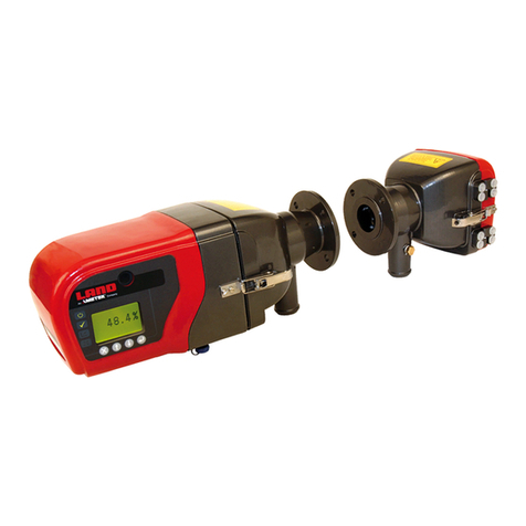
Ametek Land 4750-PM User manual

4750-PM Particulate Measurement System
i
4750-PM
USER GUIDE
PUBLICATION NO813214
LANGUAGE: ENGLISH
ISSUE: 1
DATE: 17 JULY 2019
QUALITY CUSTOMER SOLUTIONS

Health and Safety Information
Read all of the instructions in this booklet - including all the WARNINGS and CAUTIONS
- before using this product. If there is any instruction which you do not understand, DO
NOT USE THE PRODUCT.
Safety Signs
WARNING
Indicates a potentially hazardous situation which, if not avoided, could result in death or
personal injury.
CAUTION
Indicates a potentially hazardous situation which, if not avoided, could result in minor or
moderate injury to the user or users, or result in damage to the product or to property.
NOTE
Indicates a potentially hazardous situation which, if not avoided, could result in damage or loss of data.
Signs and Symbols used on equipment and Documentation
Caution, risk of electric shock.
Caution, attention to possibility of risk of damage to the product, process or surroundings. Refer
to instruction manual.
Caution, hot surface.
Protective Conductor Terminal.
Observe precautions for handling electrostatic discharge sensitive devices.
Equipment Operation
Use of this instrument in a manner not specied by AMETEK Land may be hazardous. Read and
understand the user documentation supplied before installing and operating the equipment.
The safety of any system incorporating this equipment is the responsibility of the assembler.
Protective Clothing, Face and Eye Protection
It is possible that this equipment is to be installed on, or near to, machinery or equipment operating at
high temperatures and high pressures. Suitable protective clothing, along with face and eye protection
must be worn. Refer to the health and safety guidelines for the machinery/equipment before installing
this product. If in doubt, contact AMETEK Land.
Electrical Power Supply
Before working on the electrical connections, all of the electrical power lines to the equipment must
be isolated. All the electrical cables and signal cables must be connected exactly as indicated in these
operating instructions. If in doubt, contact AMETEK Land.
Storage
The instrument should be stored in its packaging, in a dry sheltered area.
The maximum storage temperature is 10 °C (18 °F) higher than the maximum operating temperature.
The minimum storage temperature is 10 °C (18 °F) lower than the minimum operating temperature.
Refer to the Technical Specication for details of the operating temperature limits.
Unpacking
Check all packages for external signs of damage. Check the contents against the packing note.
Lifting Instructions
Where items are too heavy to be lifted manually, use suitably rated lifting equipment. Refer to the
Technical Specication for weights. All lifting should be carried out in accordance with local and national
regulations.
IMPORTANT INFORMATION - PLEASE READ
Contact Us
UK - Droneld
Land Instruments International
Tel: +44 (0) 1246 417691
USA - Pittsburgh
AMETEK Land, Inc.
Tel: +1 412 826 4444
China
AMETEK Land China Service
Tel: +86 21 5868 5111 ext 122
India
AMETEK Land India Service
Tel: +91 - 80 67823240
Web: www.ametek-land.com
For further details on all AMETEK Land oces, distributors and representatives, please visit our website.
Return of Damaged Goods
IMPORTANT If any item has been damaged in transit, this should be reported to the carrier and to the
supplier immediately. Damage caused in transit is the responsibility of the carrier not the supplier.
DO NOT RETURN a damaged instrument to the sender as the carrier will not then consider a claim. Save
the packing with the damaged article for inspection by the carrier.
Return of Goods for Repair
If you need to return goods for repair please contact our Customer Service Department for details of the
correct returns procedure.
Any item returned to AMETEK Land should be adequately packaged to prevent damage during transit.
You must include a written report of the problem together with your own name and contact information,
address, telephone number, email address etc.
Design and Manufacturing Standards
The Quality Management System of Land Instruments International is approved to BS EN ISO 9001 for
the design, manufacture and on-site servicing of combustion, environmental monitoring and non-contact
temperature measuring instrumentation.
Registered ISO 9001 Management System approvals apply in the USA.
UK Calibration Laboratory: UKAS 0034.
USA Calibration Laboratory: ANAB Accredited ISO/IEC 17025.
National Accreditation Board for Testing and Calibration Laboratories approvals apply in India.
Operation of radio transmitters, telephones or other electrical/electronic devices in close proximity
to the equipment while the enclosure doors of the instrument or its peripherals are open, may cause
interference and possible failure where the radiated emissions exceed the EMC directive.
The protection provided by this product may be invalidated if alterations or additions are made to the
structural, electrical, mechanical, pneumatic, software or rmware components of this system. Such
changes may also invalidate the standard terms of warranty.
Copyright
This manual is provided as an aid to owners of AMETEK Land’s products and contains information
proprietary to AMETEK Land. This manual may not, in whole or part, be copied, or reproduced without the
expressed written consent of AMETEK Land.

Health and Safety Information
Read all of the instructions in this booklet - including all the WARNINGS and CAUTIONS
- before using this product. If there is any instruction which you do not understand, DO
NOT USE THE PRODUCT.
Safety Signs
WARNING
Indicates a potentially hazardous situation which, if not avoided, could result in death or
personal injury.
CAUTION
Indicates a potentially hazardous situation which, if not avoided, could result in minor or
moderate injury to the user or users, or result in damage to the product or to property.
NOTE
Indicates a potentially hazardous situation which, if not avoided, could result in damage or loss of data.
Signs and Symbols used on equipment and Documentation
Caution, risk of electric shock.
Caution, attention to possibility of risk of damage to the product, process or surroundings. Refer
to instruction manual.
Caution, hot surface.
Protective Conductor Terminal.
Observe precautions for handling electrostatic discharge sensitive devices.
Equipment Operation
Use of this instrument in a manner not specied by AMETEK Land may be hazardous. Read and
understand the user documentation supplied before installing and operating the equipment.
The safety of any system incorporating this equipment is the responsibility of the assembler.
Protective Clothing, Face and Eye Protection
It is possible that this equipment is to be installed on, or near to, machinery or equipment operating at
high temperatures and high pressures. Suitable protective clothing, along with face and eye protection
must be worn. Refer to the health and safety guidelines for the machinery/equipment before installing
this product. If in doubt, contact AMETEK Land.
Electrical Power Supply
Before working on the electrical connections, all of the electrical power lines to the equipment must
be isolated. All the electrical cables and signal cables must be connected exactly as indicated in these
operating instructions. If in doubt, contact AMETEK Land.
Storage
The instrument should be stored in its packaging, in a dry sheltered area.
The maximum storage temperature is 10 °C (18 °F) higher than the maximum operating temperature.
The minimum storage temperature is 10 °C (18 °F) lower than the minimum operating temperature.
Refer to the Technical Specication for details of the operating temperature limits.
Unpacking
Check all packages for external signs of damage. Check the contents against the packing note.
Lifting Instructions
Where items are too heavy to be lifted manually, use suitably rated lifting equipment. Refer to the
Technical Specication for weights. All lifting should be carried out in accordance with local and national
regulations.
IMPORTANT INFORMATION - PLEASE READ
Contact Us
UK - Droneld
Land Instruments International
Tel: +44 (0) 1246 417691
USA - Pittsburgh
AMETEK Land, Inc.
Tel: +1 412 826 4444
China
AMETEK Land China Service
Tel: +86 21 5868 5111 ext 122
India
AMETEK Land India Service
Tel: +91 - 80 67823240
Email: [email protected]
Web: www.ametek-land.com
For further details on all AMETEK Land oces, distributors and representatives, please visit our website.
Return of Damaged Goods
IMPORTANT If any item has been damaged in transit, this should be reported to the carrier and to the
supplier immediately. Damage caused in transit is the responsibility of the carrier not the supplier.
DO NOT RETURN a damaged instrument to the sender as the carrier will not then consider a claim. Save
the packing with the damaged article for inspection by the carrier.
Return of Goods for Repair
If you need to return goods for repair please contact our Customer Service Department for details of the
correct returns procedure.
Any item returned to AMETEK Land should be adequately packaged to prevent damage during transit.
You must include a written report of the problem together with your own name and contact information,
address, telephone number, email address etc.
Design and Manufacturing Standards
The Quality Management System of Land Instruments International is approved to BS EN ISO 9001 for
the design, manufacture and on-site servicing of combustion, environmental monitoring and non-contact
temperature measuring instrumentation.
Registered ISO 9001 Management System approvals apply in the USA.
UK Calibration Laboratory: UKAS 0034.
USA Calibration Laboratory: ANAB Accredited ISO/IEC 17025.
National Accreditation Board for Testing and Calibration Laboratories approvals apply in India.
Operation of radio transmitters, telephones or other electrical/electronic devices in close proximity
to the equipment while the enclosure doors of the instrument or its peripherals are open, may cause
interference and possible failure where the radiated emissions exceed the EMC directive.
The protection provided by this product may be invalidated if alterations or additions are made to the
structural, electrical, mechanical, pneumatic, software or rmware components of this system. Such
changes may also invalidate the standard terms of warranty.
Copyright
This manual is provided as an aid to owners of AMETEK Land’s products and contains information
proprietary to AMETEK Land. This manual may not, in whole or part, be copied, or reproduced without the
expressed written consent of AMETEK Land.
Copyright © 2019 Land Instruments International

Particulate Measurement System
User Guide
4750-PM
Blank

4750-PMParticulate Measurement System
User Guide
Contents
1 Introduction 1-1
1.1 Purpose of this Manual 1-1
1.2 Product Safety 1-1
1.3 Safety Procedures 1-2
1.4 Intended Use 1-3
1.5 Additional Information 1-4
1.6 Certication 1-4
2 Technical Data 2-0
2.1 Process and Application Conditions 2-0
2.2 4750-PMSensorSpecication 2-0
2.3 Cabling 2-5
3 Product Description 3-1
3.1 About the 4750-PM 3-1
3.2 Components 3-1
3.3 Sensor 3-3
3.4 Purge Air Blower 3-4
3.5 Principle of Operation 3-5
4 Installation 4-1
4.1 Unpacking and Inspection 4-1
4.2 Preparation – Overview of Process 4-1
4.3 Prerequisites and Guidelines 4-2
4.4 Installing the Sensor 4-4
4.5 Connecting the Sensor 4-6
4.6 Power-up Quick Check 4-11
5 Operation 5-1
5.1 Sensor Settings Overview 5-1
5.2 Standard Menu 5-2
5.3 Engineering Menu 5-6
5.4 Modbus Diagnostics [MOD.R, MOD.E] 5-10
5.5 Data Communication 5-12
5.6 Sensor Checks and Controls 5-12
5.7 Auditing the Sensor 5-13
6 Maintenance 6-0
6.1 Safety Information 6-0
6.2 Preventative Maintenance Plan 6-1
6.3 Cleaning the Sensor 6-1
6.4 Changing the Fuse (Mains-powered Sensors only) 6-3
6.5 Troubleshooting 6-4
7 Resetting the Sensor 7-0
8 General Notices 8-0
Compliance 8-0

INTRODUCTION
1

1 - 1User Guide
Particulate Measurement System 4750-PM
1Introduction
1.1 Purpose of this Manual
This manual contains all information necessary for the correct installation,
setup, operation, and maintenance of the instrument. The procedures given
inthismanualmustbecarriedoutonlybysuitablytrainedandqualied
personnel.
1.2 Product Safety
The following symbols are used throughout this manual to indicate
procedures that, if not followed correctly, may result in personal injury or
damage to equipment.
WARNING!
Alerts the user to a procedure or practice which, if not followed
correctly, can result in personal injury, injury of others, or death.
CAUTION!
Alerts the user to a procedure or practice which, if not followed
correctly, can result in damage to the system or ancillary
equipment.
NOTES are used to highlight important information that assist the user in
carrying out a procedure or in understanding the text.
In addition, the following symbols are used on the product:
WARNING!
Risk of electric shock.
WARNING!
Laser radiation.
1.2.1 Danger from Process
It is possible that the sensor is installed in ducting that contains process
particulate(andotheruegasconstituents)hazardoustohealth.Thismay
take one or more of the following forms:
• Particulatewhichisammableorexplosive
• Particulatewhichistoxicorinsomeotherwayhazardoustohealth
• Particulate contained within high-temperature gas.
Take Precautionary Measures
Unless the process conditions are known to be entirely safe, suitable
precautions such as the use of breathing apparatus or duct purging/
detoxifying must be employed before any entry is made into the duct for
installation or maintenance purposes. If in doubt, consult your local Safety
Ocerand/orlocalsafetyprocedures.

User Guide1 - 2
Particulate Measurement System4750-PM
1.3 Safety Procedures
Always observe the following safety precautions. Personnel installing,
operating, or maintaining the equipment are responsible for their personal
safety, and for the correct handling and use of the equipment in accordance
with the safety procedures detailed in this manual.
Follow all warnings and instructions marked on the product and in this
manual.Warninglabelsaresituatedonthesystem,indicatingahazardat
or near the location of the warning label. These safety instructions must be
followed to avoid possible personal injury, injury to others, and damage to
the product.
Iftheequipmentisusedinamannernotspeciedinthismanual,the
protection provided by the equipment may be impaired.
Retain these instructions in a safe and known place for future use.
WARNING!
Risk of personal injury or injury to others. All personnel must be
fullytrainedandadheretolocaland,ifapplicable,site-specic
health and safety laws and guidelines.
It is the responsibility of the local organizations to enforce safe
working practices at all times.
WARNING!
Risk of electric shock. Only connect to an earthed supply. This
unit is a Class 1 construction and must be connected to a
protective earth connection (GND).
WARNING!
This product must be connected to a power supply of the same
voltage(V)andfrequency(Hz)asindicatedontheproduct
rating plate and provided in the TECHNICAL DATA section of this
manual.
A supply cable with adequate rating must be used. Temperature
de-rating must be considered.
WARNING!
Risk of electric shock. For mains powered units – ensure that
mains isolation devices are easily accessible (within a 2 m / 6½ ft.
radius) to allow the sensor and purge blower to be switched OFF
when at the units.
WARNING!
Hearing damage. Running the blower produces high sound
pressure levels. Prolonged unprotected exposure may cause
hearing damage. Use suitable personal protective equipment
(PPE).

1 - 3User Guide
Particulate Measurement System 4750-PM
WARNING!
Laser radiation. This product contains a Class 3R laser.
Avoid direct eye exposure to the emitted laser radiation
at all times during installation, maintenance, and normal
operation.
Use of controls or adjustments or performance of procedures
otherthanthosespeciedinthismanualcanresultinhazardous
radiation exposure.
CAUTION!
Position the unit to avoid excessive heat, vibration, humidity,
and dust.
CAUTION!
Failuretoserviceormaintaintheproduct,ttingnon-approved
parts, or carrying out non-approved alterations or servicing can
bedangerousandcouldaectthesafetyoftheproduct.Itmay
also invalidate the terms and conditions of the product warranty
1.4 Intended Use
The 4750-PM is a continuous particulate monitoring instrument suitable
formeasuringdustconcentrationsandmonitoringlterperformancein
medium to large stacks for industrial and combustion processes. The sensor
illuminates particles in the stack with laser light to detect and measure the
amount of back-scattered light. The measurement of back-scattered light is
ampliedandprocessedbytheonboardelectronics.
The instrument can measure very low to high dust concentrations, making
itsuitableformonitoringlterperformanceinchemical,metal,and
mineral plants, and for continuous emission monitoring in power plants
andcombustionprocesses,includingreneryboilersandmetal-smelting
applications.
1.4.1 Limits of Use
To achieve optimum performance and safe operation the equipment must
be operated within the limits detailed in the TECHNICAL DATA section of
this manual. Operation outside these limits may result in damage to the
equipmentorfailuretoachievetheperformancespecication.
Pollution Degree 2
This equipment is designed for operation in Pollution Degree 2 environments
(where only non-conductive pollution occurs, except that occasionally a
temporary conductivity caused by condensation is expected).

User Guide1 - 4
Particulate Measurement System4750-PM
Overvoltage Category II
Overvoltage Category II is for equipment or instruments intended to be
supplied from the building wiring. It applies both to PLUG-CONNECTED
EQUIPMENT and to PERMANENTLY CONNECTED EQUIPMENT.
1.5 Additional Information
1.5.1 List of Abbreviations
The following abbreviations and terms are used in this manual:
Acronym Meaning
AEL Accessible Emission Limit (for lasers)
CF Calibration factor
HRC High rupturing capacity (fuse)
L/min Litresperminute(purgeairowrate)
MAU Manual Audit Unit
min./max. minimum/maximum
n/a not applicable
PPE Personal protective equipment
SPCO Single pole, changeover (electrical switch)
1.6 Certification
1.6.1 Conformance and related Standards
AMETEKLanddeclaresthatthisinstrument—withinthelimitsspeciedinthis
manual—complies with the essential requirements and other provisions of
the following European Union Directives: Low Voltage Directive (LVD), EMC
Directive.
For details refer to the Declaration of Conformance for this instrument or
system.
1.6.2 Laser Standards
This product is designed to be compliant with the following laser standards:
IEC 60825-1:2014
Safety of laser products –
Part1:Equipmentclassication
and requirements
Class 3R lasers have a maximum output
power of 5mW (or 5 times the AEL for a
Class 1 product). Radiation in this class
is considered low risk, but potentially
hazardous.
US Federal Laser Product Performance Standard (FLPPS)
21 CFR, Parts 1040 (Performance Standards for Light-Emitting Products), Title
21,sections10(laserproducts)and11(specicpurposelaserproducts).
Note: under Laser Notice 50, the FDA accepts classication and labelling to
IEC 60825-1.

TECHNICAL DATA
2

Particulate Measurement System
User Guide
4750-PM
2Technical Data
2.1 Process and Application Conditions
Stack temperature range
(at monitoring point)
-20 to 250°C (-4 to 480 °F)
Option: up to 400°C (750 °F)
Stack pressure ±20 mb(g)
Stack diameterBØ1.5 to 15 m (5 to 50 ft.)
Sensor – Key Data
Measurement type Dust concentration (in mg/m³)
Measurement capability 0 – 1000 mg/m³
Resolution 0.1 mg/m³
Zero drift <3%
Span drift <3%
Response time 2 seconds
Environmental
information
Application conditions Suitableformeasurementinnon-condensingue
gases.
Note: not recommended for use in applications
with water droplets
Location This equipment is for outdoor or sheltered use.
2.2 4750-PM Sensor Specification
Sensor version Standard sensor: 0 – 250°C (up to 480 °F)
Weight 9.6 kg (21 lb)
Overall dimensions L 354 x H 216 x B 204mm (14 x 8.5 x 8 in.)
incl.angeandcableglands
Enclosure
Temperature range -20 to 50°C (-4 to 120 °F), ambientC
Dimensions W 199 x H 180 x D 107mm (7.8 x 7 x 4.2 in.),
incl. glands and hinges
Protection rating IP65
Material Die-cast aluminium LM6M (epoxy coated)
Cable entries 3 x M20 cable glands
BInclude stando length (see Section 4.4.2 for details).
CCare should be taken to install the instrument out of direct sunlight to
minimize the eect of radiating heat, which may subject the sensor to
temperatures above +50 °C (120 °F).
2 - 0

2 - 1User Guide
Particulate Measurement System 4750-PM
Features • Emission and warning alarm levels
• Sensor checks:
• Zero and Reference checks
• Purge Air Flow self-check
• Password protection
• Calibration (internal)
• External status indicators
I/O
Outputs
1 x 4-20 mA:
•Max.load500Ω
• Isolated
• Max. working insulation voltage is
560Vpeak
2 x Alarm relays :
• Voltage free
• Max. 24V DC or AC r.m.s nominal (18–36 V
DC range), 0.5A
•Insulationresistance1GΩ@500VDC
1 x RS-485 output
Inputs 1 x digital input:
• Isolated
• Max. working insulation voltage is
560Vpeak
• Reverse polarity protected
Power Requirements
Power Supply Voltage 100to240VAC,50/60Hz,1A
Power Consumption 1.7W/2.2W(@24V)
FuseD5 mm x 20mm HRC, type T1AH250V
(approvedtoIEC60127,ULrecognized)
Additional Requirements
Air Purge requirements
Requires an external supply of 1,000l/min of dry,
clean (oil-free) air.
A suitable purge blower unit is available. For
details refer to the table in Section 5.6.1
Laser This product is equipped with a Class 3R laser.
Max. power output = 5mW, Wavelength = 650nm
WARNING!
Laser radiation. This product contains a Class 3R laser.
Avoid direct eye exposure at all times !
D AMETEK Land recommends the following approved fuses: Schurter type
SMD-SPT 0001.2704 or Cooper-Bussmann S505-1-R.

User Guide2 - 2
Particulate Measurement System4750-PM
2.2.1 Quality Assurance
Zero and Span Checks Manually initiated (on demand)
Air Purge Flow self-check
(option)
Continuously monitors the purge air feed to
detecta‘lowow’or‘noow’condition.E
Auditing Single-value Manual Audit Unit (MAU)
EThis feature includes an optical shield to protect the instrument’s
optics by minimizing ue gas deposition onto optical surfaces (see
Section 4.3.7).
2.2.2 Dimensional Drawings - Sensor
(a) Side view (incl. blower hose) (c) Enclosure dimensions (excl. hinges, glands)
(b) Front view (excl. blower hose) (d) Flange dimensions (rear view)

2 - 3User Guide
Particulate Measurement System 4750-PM

User Guide2 - 4
Particulate Measurement System4750-PM
2.2.3 Sensor Options
Stack Connection •3in150lbANSIange
•DN80PN10/PN16ange
•JIS100-5k,-10kange
Eight slots (19 x 31.5mm /0.7 x 1.2in) on a PCD of
Ø 156 mm (Ø 6 in).
Mounting hole ID: Ø80 to 110 mm (Ø3.2 to 4.3in).
Additional Options • Optical shield (to protect the optical elements)
• Flue gas blocker (stack cover plate)
• Medium Purge Blower (see Section 2.2.4)
HazardousZones
Classication
Refer to the relevant Ex manual. See also Product
Parts and Options for more information.

2 - 5User Guide
Particulate Measurement System 4750-PM
2.2.4 Purge Air Blower (Option)
Type Medium Purge Blower
Power supply voltages
(options)
•110VAC,50/60Hz,7A
•230VAC,50/60Hz,2.3A
Blower Tubing 3m(10ft.)hosewithttings(supplied)
Air Filter Standard (included); recommended change: every
1–3 months, depending on ambient conditions
Noise Pressure Level >80 dBA
Cable Entries 1 x M20 cable gland
Optional Accessories
Weather Cover Recommended for adverse conditions, including
torrential rain, snow, and high ambient temperatures.
Ambient temperature rating: -20 to +50 °C
(-4 to 120°F)
Dimensions: W 480 x H 324 x 259mm
(18.9 x 12.8 x 10.2in)
2.3 Cabling
All cabling should be rated for use up to +65°C (150 °F) at least to allow for
an ambient temperature of up to +50°C (120 °F).
Cables supplied by AMETEK Land meet these requirements.
Maximum Cable Lengths RS-485: 1,000 m (0.6mi/ 3,300 ft nom.)
2.3.1 Power Supply Cable Specification
For mains power connections use an appropriate cable with a conductor area
range from 0.75 – 2.5mm², in accordance with your local regulations.
A suitable approved and rated two-pole mains isolation device (and separate
fuse) must be clearly marked and installed close to the instrument (within a
2 m/6½ft radius), so that it is accessible when at the unit. The contact gap of
the disconnect device must be at least 3 mm. See also Section 4.3.4.
2.3.2 Data Cable Specification
The minimum requirements for network cabling are outlined in the following
table. Cables supplied by AMETEK Land meet these requirements.
Type 4-core (2-pair) cable
ConductorSize 0.5mm² (16/0.2)
Current Rating Max 1A rms (per core)
Working Voltage Max 440V rms
Cable Shielding Flame retardant PVC outer sheath (OD Ø7.9mm/0.3 in),
with overall tinned copper, braided or foil screen.
Note: for electrically noisy environments the use of a
braided, screened cable is recommended. For very noisy
environments, use a cable with multiple layers of foil and
braid shielding.
Resistance <40Ω/km(12.192Ω/kft),recommendedforlongcableruns
Compliance BS5308 part 2, type 1

PRODUCT
DESCRIPTION
3

3 - 1User Guide
Particulate Measurement System 4750-PM
3Product Description
3.1 About the 4750-PM
The 4750-PM backscatter sensor with two external status indicators and
protected, internal user controls is suitable for measuring dust concentrations
andmonitoringlterperformanceinmediumtolargestacksorducts
for industrial and combustion processes. The sensor can measure dust
concentrations as low as 0.1mg/m³, making it particularly suitable for the
lowdustlevelsfoundafterbaglters.Itisunaectedbychangesinuegas
velocity associated with variable speed fans or plant-load changes and, for a
givenparticlesizeandtype,theinstrumentresponseisproportionaltodust
concentration.
The instrument has been designed to comply with the TUV suitability testing
scheme to EN 15267 and, due to its wide dynamic operating range, may be
usedinhigherdustloadingapplicationsaswellasforprocessoptimization
applications.
3.2 Components
3.2.1 4750-PM Sensor
1 Sensor enclosure with hinged lid 5 Purge Air Flow sensor
2 Hinged sensor body 6 Purgeairsupply(exibletubewith
hose clip)
3Inbuiltange(sensor-to-stack
connection)
7M20cableglands(3o)
4 Quick-release clamp 8 Sensor interface with external status
indicators(2o)
Fig. 3-1 4750-PM Sensor

User Guide3 - 2
Particulate Measurement System4750-PM
3.2.2 Sensor Display and Controls
1M20cableglands(3o) 3 Self-check LED
2Hingedenclosurelid(with4o
screws)
4 Power/Comms LED
Fig. 3-2 4750-PM Sensor Display and Controls
Table of contents
Other Ametek Land Measuring Instrument manuals

Ametek Land
Ametek Land SPOT+ User manual

Ametek Land
Ametek Land LANCOM 4 User manual

Ametek Land
Ametek Land LANCOM 4 User manual

Ametek Land
Ametek Land 4500 MKIII User manual

Ametek Land
Ametek Land CYCLOPS L User manual

Ametek Land
Ametek Land Lancom 200 User manual

Ametek Land
Ametek Land VIRALERT 3 User manual
Popular Measuring Instrument manuals by other brands

Kanomax
Kanomax 1580 user manual

Teledyne
Teledyne 8800T instruction manual

KROHNE
KROHNE H250 M40 Series Supplementary instructions

Hach
Hach sensION3 Quick reference card

Spectrum Technologies
Spectrum Technologies Field Scout TCM 500 manual

LumaSense technologies
LumaSense technologies IMPAC IS 140 Operation manual