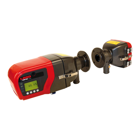
Ametek Land LANCOM 4 User manual

LANCOM 4 Portable Flue Gas Analyser
i
LANCOM 4
USER GUIDE
PUBLICATION NO806885
LANGUAGE: ENGLISH
QUALITY CUSTOMER SOLUTIONS

Health and Safety Information
Read all of the instructions in this booklet - including all the WARNINGS and CAUTIONS
- before using this product. If there is any instruction which you do not understand, DO
NOT USE THE PRODUCT.
Safety Signs
WARNING
Indicates a potentially hazardous situation which, if not avoided, could result in death or
personal injury.
CAUTION
Indicates a potentially hazardous situation which, if not avoided, could result in minor or
moderate injury to the user or users, or result in damage to the product or to property.
NOTE
Indicates a potentially hazardous situation which, if not avoided, could result in damage or loss of data.
Signs and Symbols used on equipment and Documentation
Caution, risk of electric shock.
Caution, attention to possibility of risk of damage to the product, process or surroundings. Refer
to instruction manual.
Caution, hot surface.
Protective Conductor Terminal.
Observe precautions for handling electrostatic discharge sensitive devices.
Equipment Operation
Use of this instrument in a manner not specied by AMETEK Land may be hazardous. Read and
understand the user documentation supplied before installing and operating the equipment.
The safety of any system incorporating this equipment is the responsibility of the assembler.
Protective Clothing, Face and Eye Protection
It is possible that this equipment is to be installed on, or near to, machinery or equipment operating at
high temperatures and high pressures. Suitable protective clothing, along with face and eye protection
must be worn. Refer to the health and safety guidelines for the machinery/equipment before installing
this product. If in doubt, contact AMETEK Land.
Electrical Power Supply
Before working on the electrical connections, all of the electrical power lines to the equipment must
be isolated. All the electrical cables and signal cables must be connected exactly as indicated in these
operating instructions. If in doubt, contact AMETEK Land.
Storage
The instrument should be stored in its packaging, in a dry sheltered area.
The maximum storage temperature is 10 °C (18 °F) higher than the maximum operating temperature.
The minimum storage temperature is 10 °C (18 °F) lower than the minimum operating temperature.
Refer to the Technical Specication for details of the operating temperature limits.
Unpacking
Check all packages for external signs of damage. Check the contents against the packing note.
Lifting Instructions
Where items are too heavy to be lifted manually, use suitably rated lifting equipment. Refer to the
Technical Specication for weights. All lifting should be carried out in accordance with local and national
regulations.
IMPORTANT INFORMATION - PLEASE READ

Contact Us
UK - Droneld
Land Instruments International
Tel: +44 (0) 1246 417691
USA - Pittsburgh
AMETEK Land, Inc.
Tel: +1 412 826 4444
China
AMETEK Land China Service
Tel: +86 21 5868 5111 ext 122
India
AMETEK Land India Service
Tel: +91 - 80 67823240
Email: [email protected]
Web: www.ametek-land.com
For further details on all AMETEK Land oces, distributors and representatives, please visit our website.
Return of Damaged Goods
IMPORTANT If any item has been damaged in transit, this should be reported to the carrier and to the
supplier immediately. Damage caused in transit is the responsibility of the carrier not the supplier.
DO NOT RETURN a damaged instrument to the sender as the carrier will not then consider a claim. Save
the packing with the damaged article for inspection by the carrier.
Return of Goods for Repair
If you need to return goods for repair please contact our Customer Service Department for details of the
correct returns procedure.
Any item returned to AMETEK Land should be adequately packaged to prevent damage during transit.
You must include a written report of the problem together with your own name and contact information,
address, telephone number, email address etc.
Design and Manufacturing Standards
The Quality Management System of Land Instruments International is approved to BS EN ISO 9001 for
the design, manufacture and on-site servicing of combustion, environmental monitoring and non-contact
temperature measuring instrumentation.
Registered ISO 9001 Management System approvals apply in the USA.
UK Calibration Laboratory: UKAS 0034.
USA Calibration Laboratory: ANAB Accredited ISO/IEC 17025.
National Accreditation Board for Testing and Calibration Laboratories approvals apply in India.
Operation of radio transmitters, telephones or other electrical/electronic devices in close proximity
to the equipment while the enclosure doors of the instrument or its peripherals are open, may cause
interference and possible failure where the radiated emissions exceed the EMC directive.
The protection provided by this product may be invalidated if alterations or additions are made to the
structural, electrical, mechanical, pneumatic, software or rmware components of this system. Such
changes may also invalidate the standard terms of warranty.
Copyright
This manual is provided as an aid to owners of AMETEK Land’s products and contains information
proprietary to AMETEK Land. This manual may not, in whole or part, be copied, or reproduced without the
expressed written consent of AMETEK Land.
Copyright © 2018 Land Instruments International.
MARCOM0311, Issue 10, 13 June 2018

Portable Flue Gas Analyser
User Guide
Lancom 4
Contents
1 About Your Analyser 1-1
1.1 About the Control Panel 1-2
1.2 LED Indicators 1-3
1.3 Probe Connections 1-3
2 Dos and Don’ts 2-1
3 Preparing the Lancom 4 for use 3-1
3.1 Connecting the Battery 3-1
3.2 Setting the Date and Time 3-2
4 Operating your Analyser 4-1
4.1 Operating Instructions 4-1
4.2 StoppingGasSamplingWithoutTurningOtheAnalyser 4-2
4.3 Using the Standard Probe 4-2
4.4 Emptying the Catch-pot 4-3
4.5 Making Draft Readings 4-3
5 Setting up the Analyser 5-1
5.1 Setting the Date and Time 5-1
5.2 Changing the Measurement Units 5-1
5.3 Oxygen Normalization 5-2
5.4 CongurationforEmissionMonitoringtoenableWetAnalysis 5-2
5.5 Calculated NO2Factor 5-3
5.6 CongurationforCombustionEciencyMeasurement 5-3
6 Alternative Probe Options 6-1
6.1 Using the Smoke Probe 6-1
6.2 Using the High Temperature Probe 6-3
6.3 Using the DrySampler Probe 6-4
6.4 Using the Flow Probe to Find the Flue Gas Velocity 6-5
6.5 Understanding Mass Flow 6-6
7 Recording Gas Readings 7-1
7.1 Using Data Logging 7-1
7.2 DeningDataLogLocations 7-2
7.3 Managementoflogles 7-3
8 About the Wake and Sleep utility 8-1
8.1 How “Wake and Sleep” Works 8-1
8.2 When should I use the Wake and Sleep option? 8-2
8.3 Setting Up Wake and Sleep 8-2
9 Output Options 9-1
9.1 Serial Communications 9-1
9.2 Printer 9-1
9.3 USB Connection to a PC 9-3
9.4 Analogue Outputs (Optional) 9-4

Lancom 4Portable Flue Gas Analyser
User Guide
10 Calibrating the Analyser 10-1
10.1 Important Safety Information 10-1
10.2 Automatic Zero Calibration 10-1
10.3 Calibration Gas Requirements 10-1
10.4 Calibration Connections 10-3
10.5 Performing an Upscale Calibration 10-3
10.6 Carbon Dioxide Sensor Zero Calibration 10-5
10.7 Oxygen Sensor Zero Calibration 10-5
11 Maintenance Procedures 11-1
11.1 Battery charging and maintenance 11-1
11.2 The Service Light 11-4
11.3 Maintenance Schedule 11-5
11.4 Maintenance Instructions 11-6
11.5 Probe assembly and Catch-pot parts 11-6
12 Spare Parts 12-1
13 Shipping Instructions 13-1
14 TechnicalSpecication 14-1
14.1 Sample Port Diameters 14-2
15 Insight PC Software 15-1
15.1 Getting Started 15-1
15.2 Example Application 15-1
15.3 Insight Software: Glossary of Icons 15-5
16 Glossary 16-1

ABOUT YOUR
ANALYSER
1

1 - 1
Lancom 4Portable Flue Gas Analyser
User Guide
1About Your Analyser
Lancom4isaportableanalyserdesignedtomeasureuegasemissions.
Upto9gasescanbemeasured,allowingyoutocheckthatyouruegas
emissions are within permitted limits, and also ensure that your combustion
processisoperatingasecientlyaspossible.
COcompensationlter
Gaspre-lter
On/O Control panel (See Section 1.1)
Catch-pot
Probe pipe
Probe handle
Sinterlter
Sample line
Data connections
Thermocouple connection
Probe connections
(See Section 1.3)
DC power inlet

Portable Flue Gas Analyser
User Guide
Lancom 4
1 - 2
1.1 About the Control Panel
Key Function Notes
On/OButton
Help Help is not currently implemented in the Lancom 4.
Home Press this key to return to the Main Menu screen.
Measurements Press this key to perform a gas analysis measurement and
go to the Gas Readings display screen.
This key performs the same function as the Measure button
(see below).
Exit Press this key to return to the previous screen.
Enter Press this key to select the highlighted option in the menu
system.
Up / Down Use the up/down keys to highlight the required menu option.
Left / Right Use the left/right keys to adjust the value of the highlighted
menu option.
Measure Press this key to perform a gas analysis measurement and
go to the Gas Readings display screen.
This key performs the same function as the Measurements
button.
Communications
ports 10101 Serial Communications port - for use with INSIGHT
software / Connection to printer / Serial communi-
cations with PC.
USB Port (Type A) - for use with USB memory stor-
age devices.
USB Port (Type B) - for connecting Lancom 4 to a
PC via USB. Lancom 4 will appear as an external
disk.DataloglescanbedownloadedtothePC.
Arrow keys
Enter key
Function KeysLED Indicators (See Section 1.2)
On/OButton Measure buttonCommunications ports

1 - 3
Lancom 4Portable Flue Gas Analyser
User Guide
1.3 Probe Connections
Probe/thermocouple connector
Flue gas port
Flow probe port
Exhaust Port (See Warning below)
1.2 LED Indicators
Standby The analyser is running in ‘Wake & sleep’ mode
On The analyser is powered and operational.
Charge The battery is being charged or the analyser is connect-
ed to an external power supply.
Low Battery Recharge the batteries. See Section 8.1.
Service Carry out routine maintenance. See Maintenance
Schedule. See Section 8.
WARNING
Exhaust Port-Whenmeasuringuegas,wastegasisemittedfromthe
exhaust port. Flue gas can be toxic. Ensure good ventilation around the
exhaust port. If you are operating the instrument in an enclosed space,
attach an extension to the exhaust port to remove exhaust gas.
Note:Gasreadingaccuracymaybeaectedifanyback-pressureis
applied to the exhaust port. Therefore, any exhaust piping must have
the largest diameter possible.

DOs AND DON’Ts
2

2 - 1
Lancom 4Portable Flue Gas Analyser
User Guide
2Dos and Don’ts
DO
Use the analyser in the
upright position.
Make sure there are no loops
in the sample line.
Connect the sample line
before operating.
Makesuretheltersarein
good condition.
Empty the catch-pot after use.
Allow the temperature of the
analyser to stabilise before
use, for example if it has been
stored in an air-conditioned
oceorahotcar.
If you are using the analyser
between locations where the
ambient temperature may
vary, use the recalibrate
function between locations to
optimise performance.
Recalibrateusingcertied
gas mixtures every 6
months. Contact LAND or an
authorised dealer for details.
Ensure that the sample
exhaust is in a well ventilated
area.
DO NOT
Abort the zero calibration –
this will result in incorrect gas
readings.
Operate the analyser on its
side – liquid in the catch-pot
mayoodtheanalyser.
Leave the Lancom 4 operating
unattended for long periods
–thecatch-potmaylland
oodtheanalyser-usethe
“wake and sleep” option
instead.
Use for extended periods
where gas concentrations are
very high.
Attempt to sample gas
without connecting the
sample line - it may cause
damage to the pump.
Operate with the catch-pot
orltersremoved-thiswill
result in incorrect readings.
Touch the probe tube after
use – it could be very hot.
Over-tighten the catch-pot.
Leave the analyser in direct
sunlight.
Use the probe without the
sinterlter.
Use the Lancom 4 in a
connedspacewithout
connecting an exhaust tube
to the sample outlet.

PREPARING THE
LANCOM 4 FOR USE
3

3 - 1
Lancom 4Portable Flue Gas Analyser
User Guide
3Preparing the Lancom 4 for use
3.1 Connecting the Battery
CAUTION
Do not short-circuit the battery terminals.
1) Unscrew the side panel screws and
remove both instrument side panels.
2) Remove the insulating sheaths from the
battery terminals. DO NOT throw away
the sheaths. They must be kept for use
in the event the instrument has to be
returned to Land for servicing.
3) Fit the red battery wires to the positive
terminals.
4) Rettheinstrumentsidepanels.
5) Connect the power supply and ensure
thechargeLEDashes,thenafterafew
seconds is lit continuously.
6) Switch the instrument ON
7) Leave the instrument to charge fully.
Side panel screws
Due to shipping regulations, your
instrument has been shipped with
the batteries disconnected.
Please follow the instructions gi
Please follow the instructions given
in the User Guide to reconnect the
batteries and prepare the instrument
for use.
WARNING
Batteries
Battery terminals

Portable Flue Gas Analyser
User Guide
Lancom 4
3 - 2
3.2 Setting the Date and Time
The date format is DAY:MONTH:YEAR.
1) In the Main Menu screen, use the up/down arrow keys to the highlight
the Settings option, then press the enter key.
The Settings screen is displayed.
2) Use the up/down arrow keys to highlight the Date and Time option,
then press the enter key. The Date and Time settings screen is
displayed.
3) Use the up/down arrow keys to highlight the required option (year,
month, hour etc.). Use the left/right keys to select the required value
for the selected option.
4) When you have set the correct date and time, press the enter key to
save the settings.
5) Press the exit button to return to the Settings screen. To return to the
Main Menu screen, press the Home button.
Cell Settling Time
The instrument sensors will achieve best accuracy 2 hours after the batteries
are connected.

OPERATING YOUR
ANALYSER
4

Portable Flue Gas Analyser
User Guide
Lancom 4
Blank

4 - 1
Lancom 4Portable Flue Gas Analyser
User Guide
4Operating your Analyser
Each time you use your analyser, check:
The catch-pot is empty and securely fastened. The catch-pot must be air
tight.
The battery is fully charged (or use the power lead).
4.1 Operating Instructions
1) Connect the sample line (1) and thermocouple (2).
2) Switch on the analyser
bypressingtheOn/O
button for approximately 3
seconds.
You will hear the internal
pump start. The Lancom
4 startup screen will be
displayed, followed by
the Calibrating Probe
countdown screen. The
countdown lasts 180
seconds. During this time,
air is passed over the
sensors in the Lancom 4
and a ‘baseline’ calibration
value established.
3) Wait for the analyser to complete the zero calibration.
Do not abort the zero calibration.
IftheLancom4isoperatedinaconnedspace,connectanextension
tube to the exhaust port.
4) Insert the probe into the stack. For more information, see Using the
Standard Probe.
5) When zero calibration is complete, the
Main Menu screen is displayed. Select
the Readings option.
6) Press the enter key to begin sampling.
The current gas readings are shown on
the display.
Press the Measurement key to see More
readings.
Wait for the gas readings to settle before you record them. This
usually takes a few minutes
7) When the gas readings have stabilised you can press the enter key to
record a log of the readings.
NOTE
Check for the build-up of liquid in the catch pot when operating the
analyser. Empty any liquid from the catch pot before and after use.
1
2

Portable Flue Gas Analyser
User Guide
Lancom 4
4 - 2
4.2 Stopping Gas Sampling Without Turning Off the Analyser
1) From the main menu select Purge and Pump O.
2) The analyser will stop sampling and pass air through the gas sensors for
about 30 seconds (Air purging).
3) When you are ready to start sampling again, select the Readings
option.
Alternatively, press the Measurement button
Mass Flow Readings
Followthesetupprocedureformassowbeforeusingmassow
rates - See Section 6.5, Understanding Mass Flow.
4.3 Using the Standard Probe
The probe should be inserted into the gas
owthroughasuitablysizedsampleport.
Probe Type Port Diameter (mm / in)
Minimum Maximum
Standard 11mm (7/16in) 16mm (5/8in)
Flow 40mm (1.6in) 55mm (2.2in)
High Temperature 11mm (7/16in) 16mm (5/8in)
Dry Sampler 11mm (7/16in) 16mm (5/8in)
Smoke 11mm (7/16in) 16mm (5/8in)
The sealing cone must form a seal in the sample port to prevent the ingress of
air (which may give a false gas reading). The sealing
cone can be moved along the probe pipe to position
the probe tip.
You can use a piece of heat proof fabric to improve the
seal. To sample gas successfully, the probe tip must
bepositionedinthemaingasow.

4 - 3
Lancom 4Portable Flue Gas Analyser
User Guide
4.4 Emptying the Catch-pot
1) Pull OUT the catch-pot from the
clip.
2) Remove the catch-pot by gently
turning clockwise.
3) Empty the catch-pot. To avoid air
leaks when replacing the catch-
pot make sure the gasket is still in
position (see Section 11.5) and the
catch-potissecurelytted.
Do not over-tighten the catch-pot.
Damage or cracking to the catch-pot can cause leaks which will
aecttheaccuracyofthegasreadings.
4.5 Making Draft Readings
The Draft Readingrepresentsthedierentialpressurebetweenthestack
pressure (taken at the probe tip) and ambient pressure. Draft readings
are made with a standard probe.
To check the draft reading insert the probe into the stack. From the main
menu select Draft Reading option. The draft readings are displayed on the
screen but cannot be recorded or printed.
To change the units, see Section 5.2.
The draft sensor must be recalibrated every 6 months. Contact LAND or an
approved distributor for more details.

SETTING UP THE
ANALYSER
5
Other manuals for LANCOM 4
3
Table of contents
Other Ametek Land Measuring Instrument manuals

Ametek Land
Ametek Land 4500 MKIII User manual

Ametek Land
Ametek Land CYCLOPS L User manual

Ametek Land
Ametek Land LANCOM 4 User manual

Ametek Land
Ametek Land VIRALERT 3 User manual

Ametek Land
Ametek Land SPOT+ User manual

Ametek Land
Ametek Land 4750-PM User manual

Ametek Land
Ametek Land Lancom 200 User manual