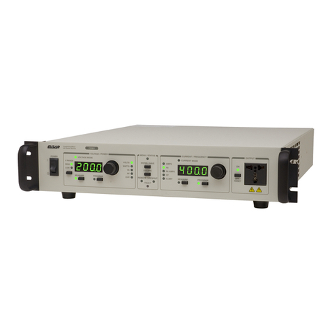
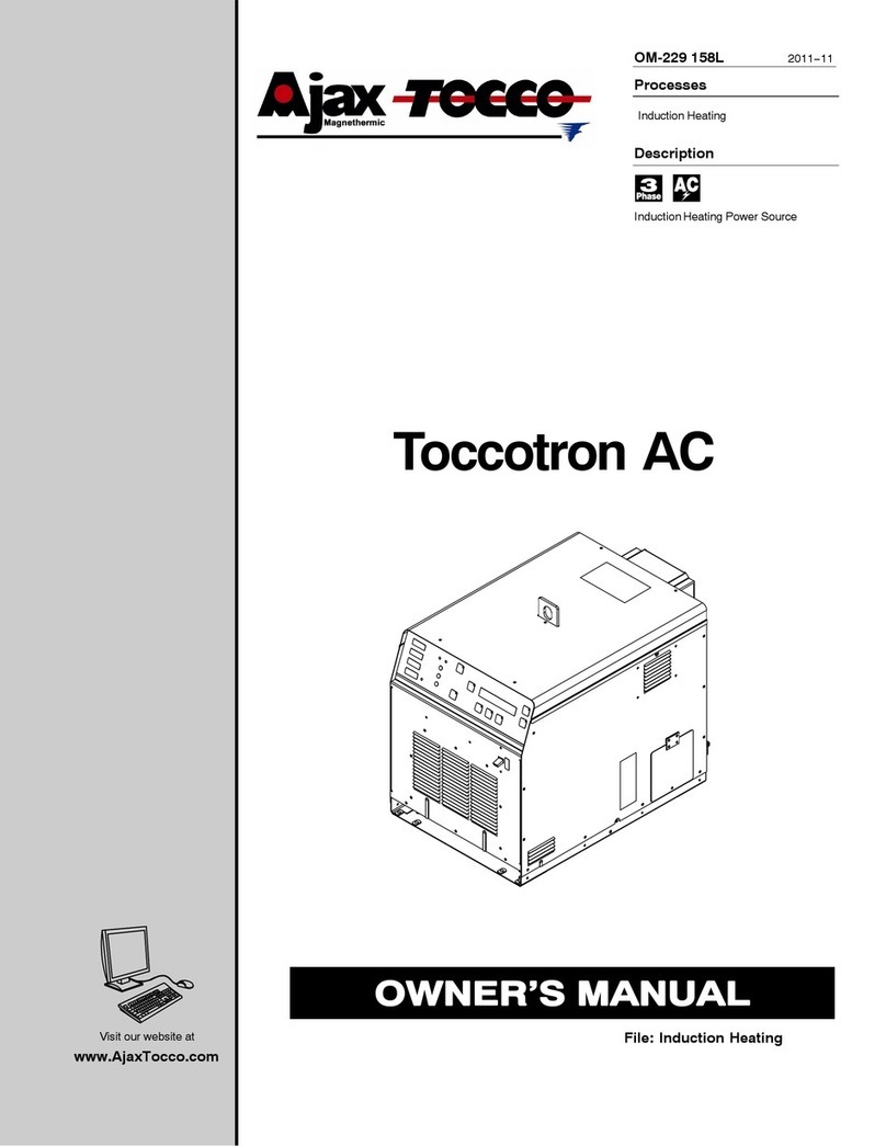
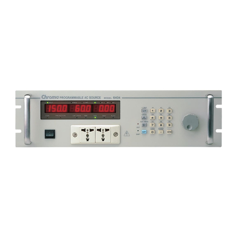
Ametek L Series User manual

L Series and FCS-18
AC Power Source
Graphical User Interface
Software User Manual
Contact Information
Telephone: 800 733 5427 (toll free in North America)
858 450 0085 (direct)
Fax: 858 458 026
Email:
Domestic Sales: domorders.sd@ametek.com
Web: www.programmablepower.com
March 2011 Document No. 4009-969 Rev D


i
About AMETEK
AMETEK Programmable Power, Inc., a Division of AMETEK, Inc., is a global leader in the design
and manufacture of precision, programmable power supplies for R&D, test and measurement,
process control, power bus simulation and power conditioning applications across diverse
industrial segments. From bench top supplies to rack-mounted industrial power subsystems,
AMETEK Programmable Power is the proud manufacturer of Elgar, Sorensen, California
Instruments and Power Ten brand power supplies.
AMETEK, Inc. is a leading global manufacturer of electronic instruments and electromechanical
devices with annualized sales of $2.5 billion. The Company has over 11,000 colleagues working
at more than 80 manufacturing facilities and more than 80 sales and service centers in the United
States and around the world.
Trademarks
AMETEK is a registered trademark of AMETEK, Inc.
Other trademarks, registered trademarks, and product names are the property of their respective
owners and are used herein for identification purposes only.
Notice of Copyright
L Series and FCS-18 AC Power Source Graphical User Interface, Software User Manual
© 2010
AMETEK Programmable Power, Inc. All rights reserved.
Exclusion for Documentation
UNLESS SPECIFICALLY AGREED TO IN WRITING, AMETEK PROGRAMMABLE POWER, INC.
(“AMETEK”):
(a) MAKES NO WARRANTY AS TO THE ACCURACY, SUFFICIENCY OR SUITABILITY OF ANY
TECHNICAL OR OTHER INFORMATION PROVIDED IN ITS MANUALS OR OTHER
DOCUMENTATION.
(b) ASSUMES NO RESPONSIBILITY OR LIABILITY FOR LOSSES, DAMAGES, COSTS OR
EXPENSES, WHETHER SPECIAL, DIRECT, INDIRECT, CONSEQUENTIAL OR INCIDENTAL,
WHICH MIGHT ARISE OUT OF THE USE OF SUCH INFORMATION. THE USE OF ANY SUCH
INFORMATION WILL BE ENTIRELY AT THE USER’S RISK, AND
(c) REMINDS YOU THAT IF THIS MANUAL IS IN ANY LANGUAGE OTHER THAN ENGLISH,
ALTHOUGH STEPS HAVE BEEN TAKEN TO MAINTAIN THE ACCURACY OF THE
TRANSLATION, THE ACCURACY CANNOT BE GUARANTEED. APPROVED AMETEK CONTENT
IS CONTAINED WITH THE ENGLISH LANGUAGE VERSION, WHICH IS POSTED AT
WWW.PROGRAMMABLEPOWER.COM.
Date and Revision
March 2011 Revision D
Part Number
4009-969
Contact Information
Telephone: 800 733 5427 (toll free in North America)
858 450 0085 (direct)
Fax: 858 458 0267
Email: sales@programmablepower.com
service@programmablepower.com
Web: www.programmablepower.com

ii
This page intentionally left blank.

iii
Important Safety Instructions
Before applying power to the system, verify that your product is configured properly for your
particular application.
WARNING
Hazardous voltages may be present when covers are removed. Qualified
personnel must use extreme caution when servicing this equipment.
Circuit boards, test points, and output voltages also may be floating above
(below) chassis ground.
WARNING
The equipment used contains ESD sensitive ports. When installing
equipment, follow ESD Safety Procedures. Electrostatic discharges might
cause damage to the equipment.
Only qualified personnel who deal with attendant hazards in power supplies, are allowed to perform
installation and servicing.
Ensure that the AC power line ground is connected properly to the Power Rack input connector or
chassis. Similarly, other power ground lines including those to application and maintenance
equipment must be grounded properly for both personnel and equipment safety.
Always ensure that facility AC input power is de-energized prior to connecting or disconnecting any
cable.
In normal operation, the operator does not have access to hazardous voltages within the chassis.
However, depending on the user’s application configuration, HIGH VOLTAGES HAZARDOUS TO
HUMAN SAFETY may be normally generated on the output terminals. The customer/user must
ensure that the output power lines are labeled properly as to the safety hazards and that any
inadvertent contact with hazardous voltages is eliminated.
Guard against risks of electrical shock during open cover checks by not touching any portion of the
electrical circuits. Even when power is off, capacitors may retain an electrical charge. Use safety
glasses during open cover checks to avoid personal injury by any sudden component failure.
Neither AMETEK Programmable Power Inc., San Diego, California, USA, nor any of the subsidiary
sales organizations can accept any responsibility for personnel, material or inconsequential injury,
loss or damage that results from improper use of the equipment and accessories.
SAFETY SYMBOLS

iv
Product Family: L Series and FCS-18
Warranty Period: One Year
WARRANTY TERMS
AMETEK Programmable Power, Inc. (“AMETEK”), provides this written warranty covering the
Product stated above, and if the Buyer discovers and notifies AMETEK in writing of any defect in
material or workmanship within the applicable warranty period stated above, then AMETEK may,
at its option: repair or replace the Product; or issue a credit note for the defective Product; or
provide the Buyer with replacement parts for the Product.
The Buyer will, at its expense, return the defective Product or parts thereof to AMETEK in
accordance with the return procedure specified below. AMETEK will, at its expense, deliver the
repaired or replaced Product or parts to the Buyer. Any warranty of AMETEK will not apply if the
Buyer is in default under the Purchase Order Agreement or where the Product or any part
thereof:
is damaged by misuse, accident, negligence or failure to maintain the same as
specified or required by AMETEK;
is damaged by modifications, alterations or attachments thereto which are not
authorized by AMETEK;
is installed or operated contrary to the instructions of AMETEK;
is opened, modified or disassembled in any way without AMETEK’s consent; or
is used in combination with items, articles or materials not authorized by AMETEK.
The Buyer may not assert any claim that the Products are not in conformity with any warranty
until the Buyer has made all payments to AMETEK provided for in the Purchase Order Agreement.
PRODUCT RETURN PROCEDURE
1. Request a Return Material Authorization (RMA) number from the repair facility (must be
done in the country in which it was purchased):
In the USA, contact the AMETEK Repair Department prior to the return of the
product to AMETEK for repair:
Telephone: 800-733-5427, ext. 2295 or ext. 2463 (toll free North America)
858-450-0085, ext. 2295 or ext. 2463 (direct)
Outside the United States, contact the nearest Authorized Service Center
(ASC). A full listing can be found either through your local distributor or our
website, www.programmablepower.com, by clicking Support and going to the
Service Centers tab.
2. When requesting an RMA, have the following information ready:
Model number
Serial number
Description of the problem
NOTE: Unauthorized returns will not be accepted and will be returned at the shipper’s expense.
NOTE: A returned product found upon inspection by AMETEK, to be in specification is subject to
an evaluation fee and applicable freight charges.

L-Series and FCS-18 Graphical User Interface User Manual
Rev D – March 2011 California Instruments 5
Table of Contents
1. Introduction .................................................................................................................................................... 9
1.1 About this program .................................................................................................................................. 9
1.2 About this manual.................................................................................................................................... 9
1.3 Software version.................................................................................................................................... 10
2. Requirements............................................................................................................................................... 11
3. Setup and Installation................................................................................................................................... 12
3.1 Connecting an L-Series AC source to PC............................................................................................. 12
3.2 Installing the LSGUI software................................................................................................................ 12
3.3 Installed files.......................................................................................................................................... 13
3.4 Manual installation................................................................................................................................. 14
3.5 Software registration.............................................................................................................................. 15
4. User Interface aspects................................................................................................................................. 19
4.1 Starting the LSGUI................................................................................................................................. 19
4.2 First : Save Configuration Data ............................................................................................................. 19
4.3 Main program window ........................................................................................................................... 20
4.4 Menu Structure...................................................................................................................................... 21
4.4.1 File menu........................................................................................................................................ 22
4.4.2 Configuration menu........................................................................................................................ 23
4.4.3 Source menu.................................................................................................................................. 24
4.4.4 Measurement menu ....................................................................................................................... 25
4.4.5 Options menu................................................................................................................................. 26
4.4.6 Applications menu.......................................................................................................................... 27
4.4.7 Help menu...................................................................................................................................... 28
4.5 Selecting menu items with the mouse................................................................................................... 29
4.6 Selecting menu items using the keyboard............................................................................................. 29
4.7 Using the Toolbar .................................................................................................................................. 30
4.8 Status bar .............................................................................................................................................. 32
4.9 Modal and Non-Modal windows ............................................................................................................ 32
5. L-Series Hardware Configuration ................................................................................................................ 33
5.1 Model Number and Controller type selection screen............................................................................ 34
5.2 System Settings screen......................................................................................................................... 35
5.3 IEEE Interface screen............................................................................................................................ 36
6. Source control.............................................................................................................................................. 37
6.1 Source Initialization................................................................................................................................ 38
6.2 Steady State control .............................................................................................................................. 39
6.3 Steady state execution modes .............................................................................................................. 40
6.3.1 Update mode.................................................................................................................................. 40
6.3.2 Immediate mode............................................................................................................................. 40
6.4 Frequency control.................................................................................................................................. 41
6.4.1 Voltage derating for low frequencies.............................................................................................. 41
6.5 Voltage Range selection........................................................................................................................ 42
6.5.1 Current limit adjustment ................................................................................................................. 42
6.6 Phase mode control............................................................................................................................... 43
6.6.1 Current limit adjustment ................................................................................................................. 43
6.7 Output relay control ............................................................................................................................... 44
6.8 Current limit delay.................................................................................................................................. 44
6.9 Phase controls....................................................................................................................................... 45
6.9.1 Voltage control ............................................................................................................................... 45
6.9.2 Current limit control........................................................................................................................ 45
6.9.3 Phase angle control........................................................................................................................ 46
6.9.4 Waveform type selection................................................................................................................ 46
7. Transients .................................................................................................................................................... 47
7.1 Transient data entry............................................................................................................................... 48
7.1.1 Transient data Entry fields.............................................................................................................. 48

L-Series and FCS-18- Graphical User Interface User Manual
6 California Instruments Rev D – March 2011
7.1.2 Error checking ................................................................................................................................50
7.2 Transient types ......................................................................................................................................51
7.2.1 Voltage dropout transient ...............................................................................................................52
7.2.2 Voltage step transient.....................................................................................................................53
7.2.3 Voltage surge or sag transient .......................................................................................................54
7.2.4 Voltage sweep transient.................................................................................................................55
7.2.5 Frequency sweep transient............................................................................................................56
7.2.6 Frequency surge or sag transient...................................................................................................57
7.2.7 Frequency sweep transient............................................................................................................58
7.2.8 Voltage and Frequency sweep transient........................................................................................59
7.3 Linking transient registers together........................................................................................................60
7.4 Transient phase selection......................................................................................................................61
7.5 Downloading transient registers ............................................................................................................62
7.6 Managing multiple transient programs ..................................................................................................63
7.6.1 Saving transient lists.......................................................................................................................63
7.6.2 Retrieving transient list...................................................................................................................63
7.6.3 Erasing transient lists .....................................................................................................................64
7.6.4 Transient list file extension.............................................................................................................65
7.6.5 Automatic save on OK....................................................................................................................65
7.7 Transient execution................................................................................................................................66
8. Measurements..............................................................................................................................................67
8.1 Selecting measurements .......................................................................................................................68
8.2 Measurement modes.............................................................................................................................69
8.3 Stay on top feature.................................................................................................................................70
8.4 Data logging...........................................................................................................................................71
8.4.1 Selecting a data file........................................................................................................................71
8.4.2 Selecting the File Mode..................................................................................................................72
8.4.3 Selecting the time stamp format.....................................................................................................72
8.4.4 Data file comments.........................................................................................................................73
8.4.5 Data File Format.............................................................................................................................73
8.5 Using a spreadsheet program ...............................................................................................................75
8.6 Dynamic data exchange ........................................................................................................................76
9. Applications..................................................................................................................................................77
9.1 MIL-STD-704 .........................................................................................................................................77
9.2 RTCA/DO-160........................................................................................................................................78
10. Calibration..................................................................................................................................................79
10.1 Calibration support features.................................................................................................................79
10.2 Unlocking calibration screens..............................................................................................................79
10.3 Output Calibration................................................................................................................................80
10.3.1 P controller ...................................................................................................................................80
10.3.2 PT controller .................................................................................................................................81
10.4 Measurement Calibration.....................................................................................................................83
11. Managing L-Series hardware configuration data.......................................................................................85
11.1 Saving configuration data ....................................................................................................................85
11.2 Restoring configuration data................................................................................................................86
11.3 Obtaining lost configuration data.........................................................................................................87
12. File Formats ...............................................................................................................................................89
12.1 Setup files (.stp)...................................................................................................................................90
12.2 Transient program files (.tls)................................................................................................................92
12.3 Data files. (.csv)...................................................................................................................................93
12.4 Measurement Calibration data files (.mcd)..........................................................................................94
13. Troubleshooting..........................................................................................................................................95
13.1 Card Not Found Problems...................................................................................................................96
13.1.1 GPIB.DLL replacement.................................................................................................................96
13.1.2 Non CIC Message........................................................................................................................96
13.1.3 Decimal separator ........................................................................................................................96
13.1.4 To resolve problems 2 and 3, follow these steps:........................................................................96
L-Series and FCS-18 Graphical User Interface User Manual
Rev D – March 2011 California Instruments 7
13.2 Interface problems............................................................................................................................. 102
13.2.1 Wrong IEEE address.................................................................................................................. 102
13.2.2 Incompatible IEEE card.............................................................................................................. 103
13.2.3 Card not at specified I/O address............................................................................................... 104
13.3 Constant or Frequent Syntax Error messages.................................................................................. 104
13.4 Configuration errors........................................................................................................................... 104
13.5 Parameter conflicts............................................................................................................................ 105
13.6 Problems not listed............................................................................................................................ 105
13.7 Problem report forms......................................................................................................................... 106
14. Index......................................................................................................................................................... 109

L-Series and FCS-18- Graphical User Interface User Manual
8 California Instruments Rev D – March 2011
(This page intentionally left blank)

L-Series and FCS-18 Graphical User Interface User Manual
Rev D – March 2011 California Instruments 9
1. Introduction
1.1 About this program
The L Series Graphical User Interface program - LSGUI - was developed
as a companion product to the California Instrument line of AC power
sources. It’s main purpose is to provide a soft front panel to the instrument
when connected to a PC through the IEEE-488 bus interface. Additional
benefits are obtained from using the PC as a control interface. Some of these
benefits include the ability to store measurement data to disk and interact
with other programs.
The LSGUI is a Windows 3.1™ program and as such requires a PC
capable of running Windows 3.1™, Windows 3.11™, Windows for
Workgroups 3.11™ or Windows 95™.
This user manual provides a complete overview of the program’s
operation. It also lists details on file formats and other details that may be
needed in order to use this program successfully. Extensive information can
also be found in the on-line help supplied with the program. Use the Help
menu or press on any of the many Help keys located in all program windows
for an explanation of the relevant screen or function.
As always, California Instruments appreciates your patronage and would
welcome any comments and suggestions you might have regarding this
software or any of its other products. Use the customer feedback form
located in the back of this manual. The same form can be used to report
software bugs should you encounter any.
1.2 About this manual
Note that this manual covers the operation of the LSGUI software only. It
is strongly recommended that you familiarize yourself with the operation of
the L-Series power source as well. This is best done by studying the
instruction manual supplied with the AC source.

L-Series and FCS-18- Graphical User Interface User Manual
10 California Instruments Rev D – March 2011
1.3 Software version
From time to time, it may be necessary to release a new version of the
LSGUI software to fix bugs and or add new features and capabilities. This
will result in the decimal portion of the version number being increased. In
this case, it is unlikely that a new user manual would be required.
Addendum’s and changes to this manual will be provided in the form of a
readme.txt file on the distribution disk. As such, you will not normally receive
an new manual when you receive a new software version. Major changes to
the functionality or operation of this software may require a new manual
version as well. In this case, the integer version number part will be
increased and a new manual version will be issued.
If the LSGUI software version you are using is 1.X with X from 0 to 9,
continue to use this manual. If the version number is 2.X or higher, contact
California Instruments to obtain an updated manual. Production and shipping
charges will apply.

L-Series and FCS-18 Graphical User Interface User Manual
2. Requirements
To successfully install and operate the LSGUI program, you will need the
following equipment :
L-Series AC power source. Supported models are : 751L 6000L
1501L 9000L
1503L 12000L
2000L 13500L
2750L 18000L1
4500L
•-P or -PT programmable controller. Manual controller (Type -M) equipped
L-Series AC sources can not be operated by this program. Contact
California Instruments for information on upgrading to a -P or -PT
controller.
•PC capable of running Windows 3.1™, Windows for Workgroups 3.11™
or Windows 95™
•National Instruments PC/IIA or PC-AT/TNT IEEE interface card. Other
vendor IEEE interface cards are not supported unless they are
compatible at the DLL level2.
•IEEE Cable
Note that the LSGUI can
be run in the absence of an
L-Series power source. If no
AC source is available or a
suitable IEEE controller card
cannot be found, the LSGUI
can be operated in a
simulation mode. The
program will detect these
conditions and start up in
simulation mode after n
be simulated and should not be used for any analytical purpose.
otifying the operator. Measurements in this case will
1This model is not available at this time and is supported for future compatibility only.
2DLL compatibility implies identical functional calls and parameters as the National Instruments GPIB.DLL.
Rev D – March 2011 California Instruments 11

L-Series and FCS-18- Graphical User Interface User Manual
12 California Instruments Rev D – March 2011
3. Setup and Installation
This section covers installation of the LSGUI from the distribution disk to
the user’s PC. Make sure the PC is capable of running Windows 3.1™
Enhanced mode or equivalent with at least 4 Mbyte of memory and 2 Mbyte
of available hard disk space.
3.1 Connecting an L-Series AC source to PC
Connect the L-Series AC source to the PC using a suitable IEEE interface
cable. Make sure you screw down the IEEE connectors securely or they will
not make good contact. The IEEE address used by the L-Series power
source is retained in non volatile memory. Factory setting is normally 1 but
this address may have been changed from the front panel.
3.2 Installing the LSGUI software
The LSGUI software is distributed on a 3.5 inch high density diskette. The
GUI must be installed from this diskette as all required files are compressed.
You cannot copy the contents of this disk to your PC hard drive and run it. To
install the LSGUI, proceed as follows :
1. Turn on the PC and boot up in Windows 3.1™.
2. Insert the LSGUI disk in drive A or B. If you do not have a 3.5 inch drive
on the PC, you can copy the contents of the disk to a 5.25 inch diskette
on a PC that is equipped with both drive types.
3. From the Program Manager, select the “File” Menu.
4. From the File Menu, select “Run...”
5. At the prompt, type “A:SETUP” or “B:SETUP” depending on the drive
designator of the drive in which you inserted the disk.
The setup program will first ask you for the destination directory on the hard
disk where you want the LSGUI installed. The default directory is “C:\LSGUI”
6. Press “Continue” if you want to accept the default. If you want the
program to reside at a different location, type in the complete path name
including hard disk drive letter and then press “Continue”. If you want to
abort the setup procedure, click on the “Exit Setup” button. A warning will
appear indicating the setup did not complete successfully. Click on the
“OK” button to acknowledge the warning. This will take you back to the
Program Manager.
7. Wait for the installation program to complete. An icon for the LSGUI, the
LSGUI help file and a program group will be created automatically.
8. Remove the diskette from the drive.
You are now ready to start using the LSGUI software.
If you experience problems during the installation process, refer to
chapter 13 on troubleshooting.

L-Series and FCS-18 Graphical User Interface User Manual
Rev D – March 2011 California Instruments 13
3.3 Installed files
The installation program will install the following files in the directories
specified. Note that files with the same name that already exists in these
directories will be overwritten as part of the installation process. As long as
the files being overwritten are of an older date (previous version), this should
not cause any problems. If however you have newer versions of some of
these files, we recommend you back these files up prior to running the
installation program and then restore them afterwards.
Application directory files:
The following files are copied to the application directory. The application
directory name is chosen by the user at the time of installation. In this
manual, the default application directory name LSGUI is used.
path and filename size in bytes date
.\lsgui\lsgui.exe 216438 9/15/95
.\lsgui\lsgui.hlp 62601 9/13/95
.
Windows system directory files:
The following support files are copied to the windows system directory:
path and filename size in bytes date
.\windows\system\fpgrid10.vbx 409200 5/12/95
.\windows\system\cmdialog.vbx 18688 4/28/93
.\windows\system\spin.vbx 22528 10/21/92
.\windows\system\threed.vbx 64432 7/17/93
.\windows\system\mhtip.vbx 35040 7/21/95
.\windows\system\mhrun400.ddl 94352 7/21/95
.\windows\system\commdlg.ddl 89248 3/10/92
.\windows\system\gpib.ddl 90624 8/31/94
.\windows\system\ver.ddl 9696 10/5/94
.\windows\system\setupkit.ddl 7008 4/28/93
.\windows\system\vbrun300.ddl 398416 6/3093

L-Series and FCS-18- Graphical User Interface User Manual
14 California Instruments Rev D – March 2011
3.4 Manual installation
If the installation program is unable to complete the installation process
successfully, you may attempt to manually install the files listed in section
3.3. All files on the distribution diskette are compressed so they cannot be
copied directly to the hard disk. Instead, use the “expand.exe” program that
is located in the DOS directory of your PC. The correct syntax to use is :
expand -r a:\source destination
The directory path for the destination files should be specified as part of the
destination.

L-Series and FCS-18 Graphical User Interface User Manual
Rev D – March 2011 California Instruments 15
3.5 Software registration
We encourage you to send in the software end-user registration form
located on the next page. Only registered users will be informed of software
updates and bug fixes that may be released from time to time. Please mail
the completed end-user registration form to the following address:
California Instruments Corporation
Attn: Customer Satisfaction Department
9689 Towne Centre Drive
San Diego, CA 92121
U.S.A.
You can also fax a copy of the form to the fax number listed below:
(858) 677-0940
(Please specify “Customer Satisfaction Department” on your fax cover page.)

L-Series and FCS-18- Graphical User Interface User Manual
16 California Instruments Rev D – March 2011
(This page intentionally left blank)
This manual suits for next models
12
Table of contents
Other Ametek AC Power Distribution manuals

Ametek
Ametek TW5250 User manual

Ametek
Ametek TW Series Owner's manual

Ametek
Ametek CS Series User manual

Ametek
Ametek 801RP Series Owner's manual

Ametek
Ametek LX series Operating and maintenance manual

Ametek
Ametek 251RP Series Owner's manual

Ametek
Ametek ESP Next Gen PCS User manual

Ametek
Ametek i Series User manual