About this Document
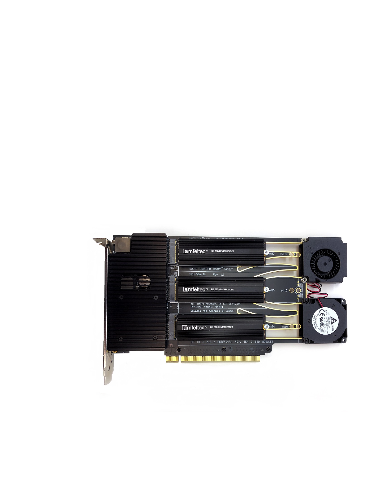
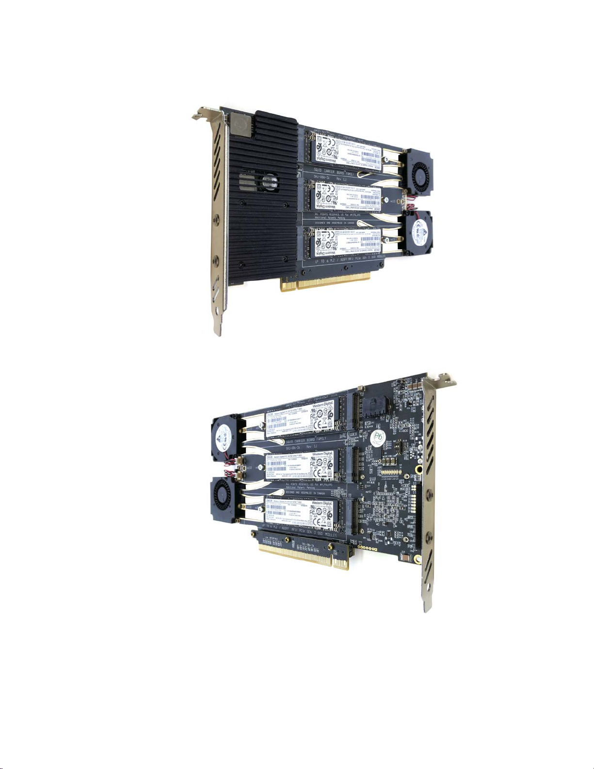
Squid PCIe Gen 3 Carrier Board™ for six M.2/NGSFF(NF1) SSD modules.
Hardware Manual, Revision 1.3
Page 2
Contents
1About this Document........................................................................................................................4
1.1 Purpose.................................................................................................................................4
1.2 Feedback..............................................................................................................................4
1.3 Revision History....................................................................................................................4
2General Description..........................................................................................................................5
2.1 Introduction...........................................................................................................................5
2.2 Package Contents.................................................................................................................6
3Features...........................................................................................................................................8
3.1 Features................................................................................................................................8
3.2 PCI Express Carrier board for six M.2/NGSFF SSD modules block diagram......................9
4Installation......................................................................................................................................10
4.1 Carrier board installation.....................................................................................................10
4.2 Carrier board Power ON.....................................................................................................10
4.3 Carrier board Power OFF. Backup status Indication..........................................................11
5Hardware Description.....................................................................................................................13
5.1 Board Layout.......................................................................................................................13
5.2 LEDs...................................................................................................................................14
5.3 Connectors..........................................................................................................................15
6Appendix A:....................................................................................................................................16
6.1 Cables.................................................................................................................................16
7Appendix B: Limited warranty.........................................................................................................19