AMGO Hydraulics XL-7 Manual

Original
On-Surface Scissors Lift
Model:XL-7

CONTENTS
Product Features and Specifications ..............................................1
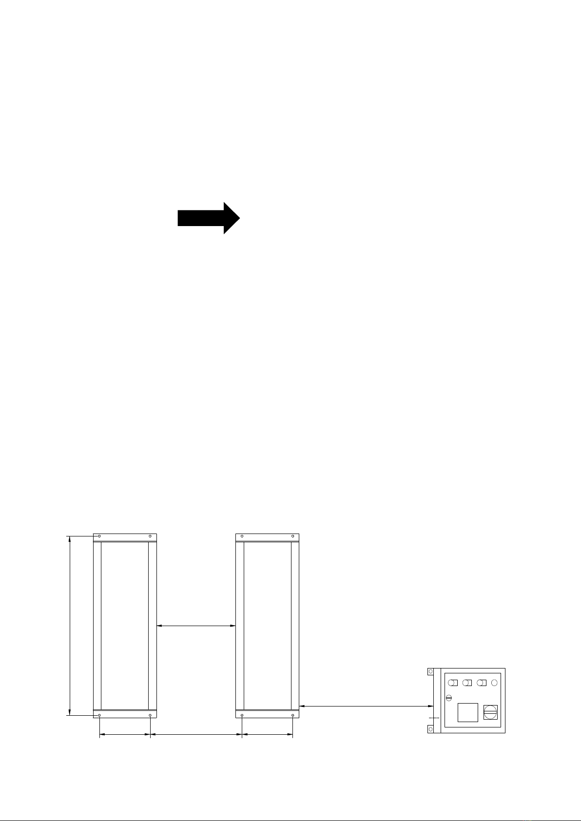
Installation Requirement .............................................................3
Steps of Installation ………………………………………………..…………………….…...4
Exploded View .........................................................................14
Test Run .................................................................................22
Operation Instruction ................................................................23
Maintenance ............................................................................24
Trouble Shooting ......................................................................25
Lift disposal .............................................................................25

1
I. PRODUCT FEATURES AND SPECIFICATIONS
ON SURFACE SCISSORS LIFT MODEL XL-7
· Electric/Hydraulic power system
· Hose burst check valve and hydraulic self-lock system
· 2-Dual synchronous cylinders are applied to assure the lifting level on both platforms
· Flow control valve to ensure the stable down speed
· Movable drive–thru ramps and extended platforms accommodate varying wheelbase
vehicles
MODEL XL-7 SPECIFICATIONS
Illustration of control cabinet installed in different way.
Model
Lifting
Capacity
Lifting
Height
Lifting
Time
Overall Length
(Inc. ramps)
Overall
Width
Min.
Height
Runway
Width
Width
Between
Runways
Motor
XL-7
7000lbs
78-3/4”
40S
81”
76 -3/4”
4-1/2”
23-1/2”
29-1/2”
2.0 HP
1
View A
Fig. 1

2
View B (Other option)
Fig. 2

3
II. INSTALLATION REQUIREMENT
A. TOOLS REQUIRED
Rotary Hammer Drill (Φ19, Φ10, Φ4) Carpenter’s Chalk
Hammer Screw Sets
Level Bar Tape Measure (7.5m)
English Spanner (12") Pliers
Wrench set (8#、17#)
Grease Gun
Lock Wrench
Ratchet Spanner With Socket (28#)
Fig. 3

4
B. Equipment storage and installation requirements.
The equipment should be stored or installed in a shady, normal temperature, ventilated
and dry place.
C. The equipment should be unload and transfer by forklift.
D. POWER SUPPLY
The electrical source must be 2.0HP minimum. The source cable size must be
2.5mm² and in good condition of contacting with floor.
III. STEPS OF INSTALLATION
A. Check the parts before assembly
1. Packaged lift, Parts box, Control cabinet and tubing cover plate (See Fig. 4).
Fig. 5
Fig. 4

5
2. Move aside the parts, open the outer packing and check the parts according to the
shipment parts list (See Fig. 5).
3. Open the parts box, check the parts according to the part list (See Fig. 7).
Fig. 6
Fig. 7
P 1
Platform
P2
Platform
Oil Hose
69

6
4. Check the parts of the parts bag according to the parts bag list (See Fig.8).
B. Location of installation
1. Concrete must be thickness 6” minimum and without reinforcing steel bars, and must
be dried completely before the installation.
2. Concrete must be in good condition and must be of test strength 3000lbs/in2
minimum.
Review the layout as shown below (Fig. 9) and select a location that is best suited for
your application.
Fig. 8
P1
P2
19”
34-1/4”
19”
29-1/1”
59-14”
118-1/4”
Fig. 9

7
C. Equipment layout and oil hose installation
Layout the equipment on the selected location according to Fig 10, and connect the oil
hose according to Fig.11.
Note: Shutoff valves should be at the working condition(Fig. 30)
Oil hose installation
Fig. 11
Main Cylinder I
Secondly Cylinder I
Main Cylinder II
Secondly cylinder II
P 1
P2
29-1/2”
P1
P2
Fig.10
○
11/4*146-1/2”
○
21/4*140-1/2”
○
31/4*137”
○
41/4*186-1/4”
○
51/4*193-3/4”
○
61/4*196”

8
D. Install electric system
1. Wire connection for hydraulic power unit (for 220V/Single phase motor)
1.1 Connect the power wire and limit switch wire according to the wiring diagram (See
Fig. 12).
1.2 Circuit Diagram (See Fig. 13).
Earth Wire
Power Wire
hydraulic
solenoid valve
Limit switch
(Wire B)
Limit switch
(Wire A)
Motor Wire
Fig. 12
Single phase
Fig. 13

9
Electric Component
2 Limit switch installation instruction
2.1 High limit switch instruction (See Fig. 14)
Item
Name
Code
Specification
1
Power switch
QS
380V AC
2
Breaker
FU1
2P
3
Breaker
FU2
1P
4
Breaker
FU3
1P
5
AC contactor
KM
24V AC
6
Limit switch
SQ(1~2)
10A
7
Hydraulic solenoid valve (Right)
Y2
AC 24V
8
Hydraulic solenoid valve (Left)
Y1
AC 24V
9
Push button
Down
Single
Lower Alarm
Duplex
10
Push Button
Up
Single
11
Motor
M
Single phase
12
Transformer
TC
24V AC
13
Alarm
H
24V AC
14
Power Indicator
R
24V AC
When the machine reaches to
78-3/4” height, the sliders will
access to the drive lever of limit
switch, and stop the lift
78-3/4”
Limit Switch
Slider block
Fig. 14

10
2.2 Lower alarm device instruction (See Fig.15)
E. Level two platforms and install anchor bolts
1. Check by level bar and use the shim to adjust the platforms until two platforms are in
the same level.
Buffer connecting bar
Limit Switch
When the machine is lowered to 11-3/4”, the
buffer connecting bar will access to the drive
lever of limit switch, and stop the lift. Pushing
the button Down while push the Lowering
Alarm Button(black) at the side of control
cabinet, the lift would be lowered down again
with tone of alarm.
Using the Level Bar
for measurement
P1
P2
Using the adjusted
shim for the level
Fig. 15
Fig. 16
11-3/4

11
2. Anchor bolts installation
2.1 Lift the machine to 39-1/2” for the anchor bolt installation.
2.2 Drilling the hole for the anchor bolt with the rotary hammer drill, type the anchor bolt
into the ground, and then fasten it with Ratchet spanner.
Note: The Torque of anchor bolt is 150 N.m, the length inside ground of anchor bolt
must be over 4-1/2”mm.
Drilling Cleaning Bolting Tighten
63
64/64A
Fig. 18
39-1/2”
Fig. 17
P1
P2
Using the anchor bolt to
fix the machine
4-1/2”

12
F. Install oil hose cover and anchor the control cabinet
1. Tidy up the oil hose and wire, cover the oil hose cover and layout the control cabinet.
(See Fig. 19, Fig 20)
Using anchor bolts to
fix the control cabinet
65
66
51
50
Fig. 19
Using the colloidal screw to
fasten the oil hose cover
Tidy up the oil hose and wire, and
then cover the oil hose cover
P1
P2
67
67
65
Using the colloidal
screw to fasten the
oil hose cover
65
66
67
68
65
65
View B Installation
Fig. 20

13
2. Install the colloidal screw of oil hose cover (See Fig. 21).
3. Install the control cabinet anchor bolt (See Fig. 22)
Drilling
Cleaning
Type the expansion
colloidal screw
Fastening by Install
the steel screw
52
53
Fig. 21
Drilling
Install screw
Tighten
Cleaning
Fig. 22
54

14
IV. EXPLODED VIEW
MODEL XL-7
Fig. 23
P1
P2
38B

15
PARTS LIST FOR XL-7
Item
Part#
Description
QTY.
Note
1
11620124
Pin For Drive-thru Ramp
8
2
10650024
Self locking nut
8
3
11620128
Drive-in Ramp
4
4
11620001B
Platform
2
5
10620034
Rubber Pad
4
6
10610070
Rubber Pad
4
7
11620129
Support frame for Drive-in Ramp (Left)
2
8
10620018
Slider Block (white)
4
9
11620026B
Upper Scissor (Out)
2
10
10203018
Socket Bolt
6
11
10420152
Washer
6
12
10206013
Limit Switch
2
13
11620011A
Scissors Pin
2
14
10620061/
10620061A
Slider Block (white)
2/ea.
15
10620117
Washer
8
16
11620030
Scissors Pin φ35*83
4
17
11620060
Plate for Limit Switch
1
18
10206032
Snap Ring φ25
16
19
11620014A
Pin for Base φ25*392
2
20
11620017B
Base
2
21
10620059
Protective Ring
3
22
10620186
Secondly Cylinder φ60*560
2
23
11620033A
Lower Scissors (in)
2
24
11620031A
Lower Scissors (Out)
2
25
10620012B
Main Cylinder φ75*560
2
26
11620007A
Buffer Connecting Bar
2
27
11620133A
Self-locking Support Plate
2
28
11620121
Pin Bush
2
29
10217020
Bronze Bush
16
29A
10620180
Graphite bronze Bush
4
30
11620025A
Cylinder Connecting Pin
2
31
11620024A
Roller
4
32
11620120
Pin Bush
2
33
11620132
Self-Locking Plate
2
34
11620131A
Connecting Plate
2
34A
11620122
Limit Block
2
34B
10209039
Lock Washer
2
34C
10720002
Socket Bolt
2
35
11620119
Pin Bush
2

16
Item
Part#
Description
QTY.
Note
36
11620010B
Buffer
2
37
10620064
Greasing Fitting
12
38
11620008A
Buffer Connecting Pin
2
38A
10620135
Washer
8
38B
10610008
Snap ring
4
39
11620028A
Connecting Pin For Upper Scissor (In)
4
39A
10640109
Washer
14
40
11620027B
Upper Scissor (In)
2
41
10620022
Self locking Nut
14
42
10203004A
Bronze Bush
48
43
11620019A
Scissors Pin
8
44
11620130
Support frame for Drive-in Ramp(Right)
2
45
10420037
Snap Ring
16
46
11620123
Connecting Shaft for support frame
8
47
10620063
Roller for Drive-in Ramp
8
48
10209010
Snap Ring
16
49
11620043
Roller Pin
8
50
10620067
Control Cabinet
1
51
071203
Electric Power Unit
1
52
10620069
Screw
42
53
10620070
Colloidal screw
42
54
10620071
Anchor Bolt
4
55
10620072
Oil Hose
6
55A
10620103
O Ring
6
55B
10620102
Seal Ring
6
56
10620152
Oil Hose No.④
1
57
10620153
Oil Hose No.③
1
58
10620154
Oil Hose No.②
1
59
10620155
Oil Hose No.⑤
1
60
10620156
Oil Hose No.①
1
61
10620157
Oil Hose No.⑥
1
62
10620079
Straight Fitting
6
63
10209059
Anchor Bolt
8
64
10620065
Shim
20
64A
10201090
Shim
20
65
11620035A
Oil hose cover (748mm)
3
66
11620066
Oil hose cover (600mm)
2
67
11510037
Oil hose cover (1060mm)
2
68
11620161
Oil hose cover
1
69
10620500A
Parts Box
1

17
4.1 Main CYLINDERS (10620012B)
Parts for Main cylinder
Item
Part#
Description
QTY.
Note
25-1
10209078
Dust Ring
4
25-2
10217243
Y- Ring
2
25-3
10620047
Support Ring
2
25-4
11620192
Head Cap (Main)
2
25-5
10620171
O- Ring
2
25-6
10630027
O-Ring
2
25-7
11620051
Piston Rod
4
25-8
11620193
Spacer For Cylinder
2
25-9
10620197
O- Ring
4
25-10
10620053
Support Ring
2
25-11
10620054
Y- Ring
4
25-12
11620194
Piston
2
25-13
10206071
Hex Nut
4
25-14
10209064
Straight fitting
4
25-15
10620127
Oil hose fitting
2
25-16
10620057
Burst Valve
4
25-17
10620125A
Oil hose ASSY.
2
25-18
11620050A
Bore weldment
2
Grease
Fig 24

18
4.2. Secondly Cylinders (10620186)
Parts for Secondly cylinder
Item
Part#
Description
QTY.
Note
22-1
10520058
O- Ring
2
22-2
10201034
Bleeding Plug
2
22-3
11620190
Head Cap
2
22-4
10620182
O- Ring
2
22-5
11620056
Bore Weldment
2
22-6
11620196
Piston
2
22-7
10217258
O- Ring
2
22-8
10217257
Y- Ring
2
22-9
10217256
Support Ring
2
Fig.25
Grease
Table of contents
Other AMGO Hydraulics Scissor Lift manuals
Popular Scissor Lift manuals by other brands

Terex
Terex Genie GS-3268DC operators manual with maintenance information

Jema Autolifte
Jema Autolifte JA2800S Installation, operation and maintenance manual

Nussbaum
Nussbaum Jumbo NT quick guide

Autoquip
Autoquip American Lifts P-25-005 manual

JLG
JLG 260MRT Service and maintenance manual

Upright
Upright LX31 Service & parts manual