Installation and Service Manual – Under-the-Counter Point of Use 5 Stage Reverse Osmosis System
Copyright © 2023 Applied Membranes, Inc.
All Rights Reserved.
Page 1
About Your RO Water Treatment System
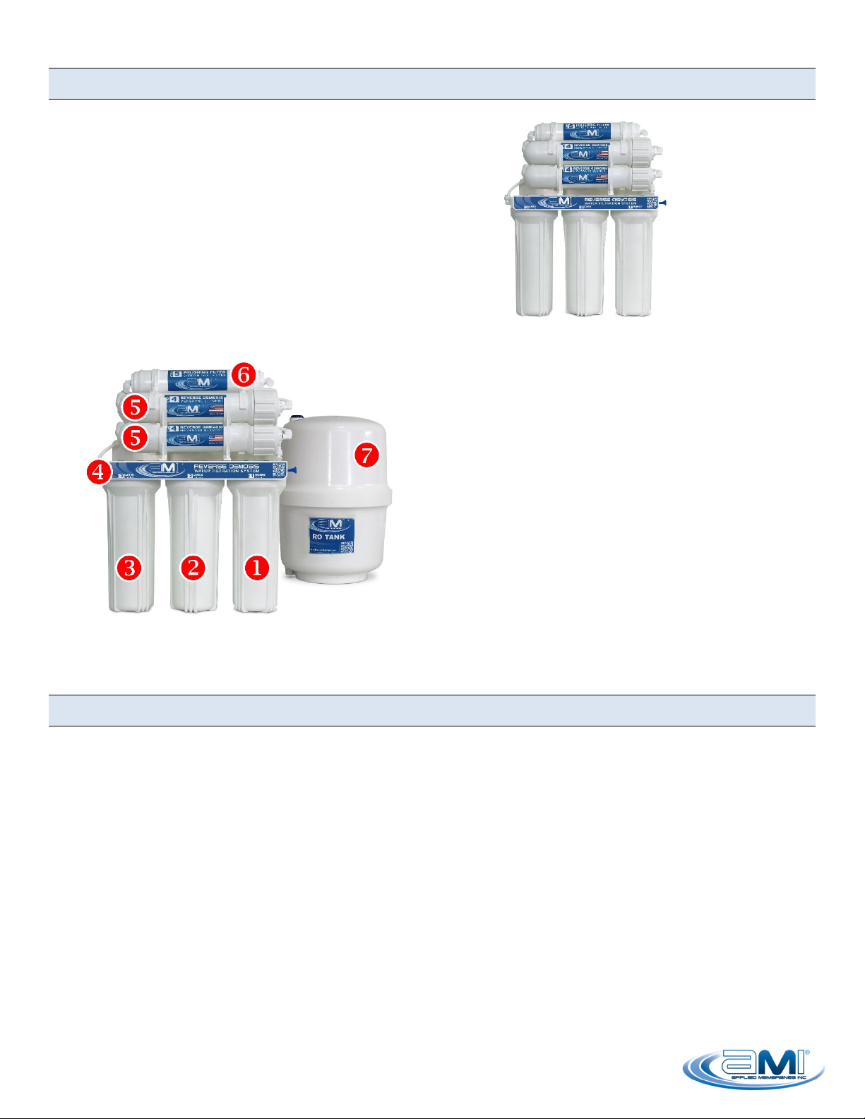
Thank you for your purchase of the AMI home RO reverse osmosis water treatment system. This drinking
water system has been designed for quick and simple installation and maintenance. By carefully reading this
instruction manual and following the operational guidelines you will ensure a successful installation and reliable
operation. Routine maintenance is essential to the longevity and performance of the system. Filters should be
changed every three to six months depending on the quality of the feed water supply.
Notice:
Please read this entire service guide prior to beginning installation.
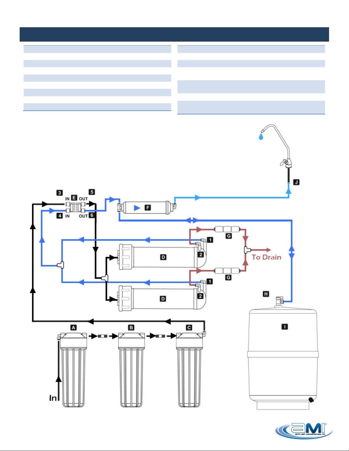
5 Stages of Water Treatment
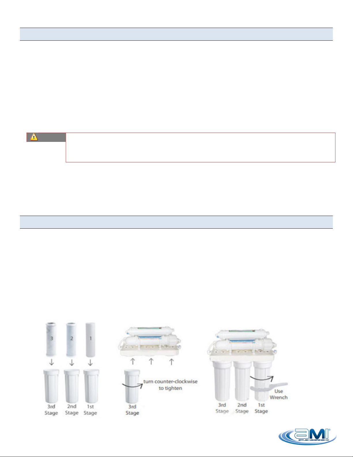
Stage1: Sediment Filter Cartridge Replace every 3-6 months
The first filter the water passes through is a five micron filter cartridge. This cartridge removes
sediment including dirt, sand, rust, grit, and other suspended matter from water. This protects the rest
of the filtration stages and equipment from damage and clogging due to buildup of sediment.
Stage 2 & 3: Carbon Block Filter Cartridges Replace every 3-6 months
Next, the water passes through two stages of carbon filters to remove chlorine, chemicals, and
objectionable tastes and odors from water. These filters also protect the membrane from exposure to
chlorine, which would damage the membrane.
Stage 4: Reverse Osmosis Membranes (2 in Parallel) Replace every 12 months
The fourth stage is the reverse osmosis membrane, which is the heart of the RO system. The RO
membrane substantially reduces the total dissolved solids (TDS) from the water, including arsenic,
barium, cadmium, chromium (hexavalent), chromium (trivalent), copper, turbidity, fluoride, lead, radium
226/228, and selenium, while washing the rejected contaminants down the drain. The treated water is
directed to the storage tank.
Stage 5: Post Carbon Filter Replace every 3-6 months
The last stage of filtration occurs as the water flows from the storage tank directly before being
dispensed from the faucet. The in-line carbon post filter (also known as polishing filter) removes any
remaining tastes or odors from the water, improving the flavor.
Notice:
Replacement frequency varies based upon incoming water quality and use patterns.
Generally speaking, filters should be changed when there is a loss of performance or
after an extended period of non-use.
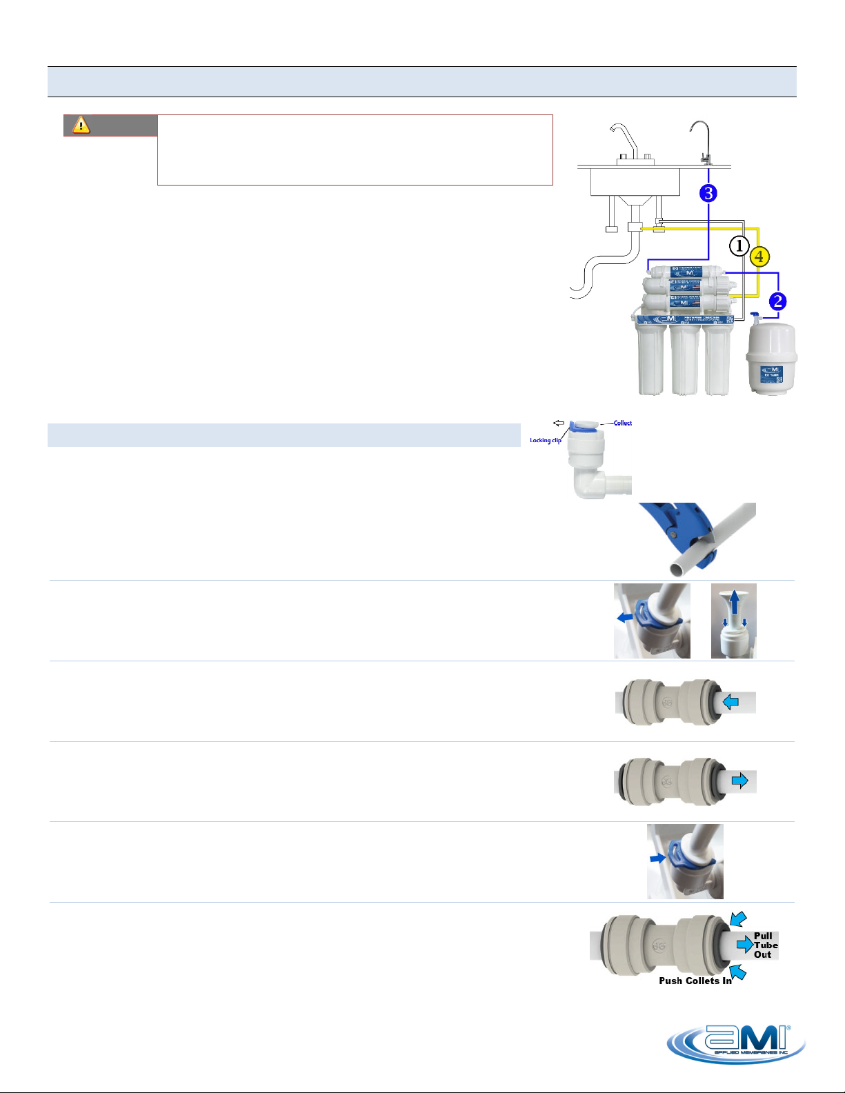
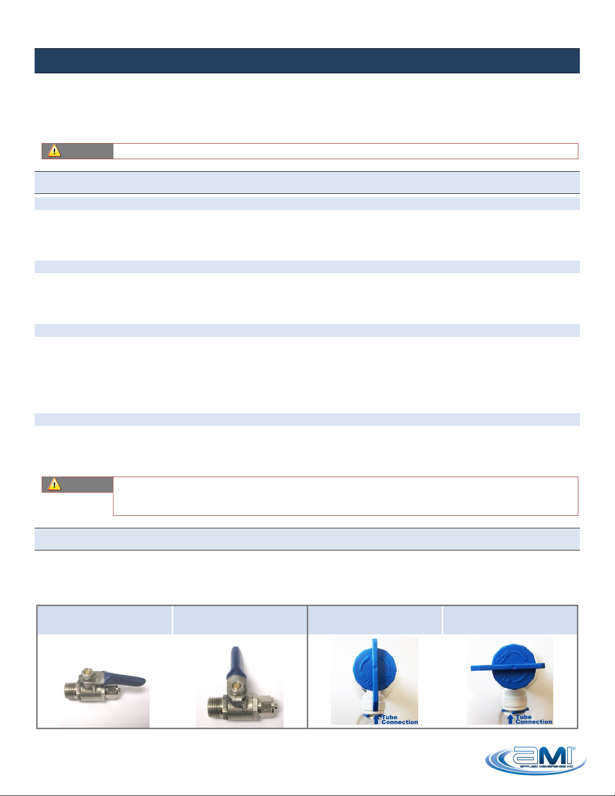
System On/Off Valves
Your RO System is equipped with two on/off ball valves. The system feed valve (to be installed into the cold
water supply line) can be used to turn the water to the system on and off for maintenance without disrupting
the water supply to the sink. The tank valve can also be closed to prevent water in the tank from draining out
during maintenance. Both can be opened by turning counterclockwise, and closed by turning clockwise.
System Feed Valve in
OPEN Position
System Feed Valve in
CLOSED Position
Tank Valve in
OPEN Position
Tank Valve in
CLOSED Position