amiad Arkal Spin Klin 2 User manual

AMIAD WATER SYSTEMS Ltd.
Arkal Spin Klin 2" with Air Aid Flushing
(AAF)
User Guide
Serial number:
_______________
Order number:
_______________
Catalog number:
_______________
Filtration degree:
_______________
Tested by:
_______________
Installation and Operation
Instructions
910101-000616 / 07.2017

FILTER TYPE 2" AAF 000616-101019 /07.2017 Page 2of 28
AMIAD WATER SYSTEMS Ltd.
Arkal Spin Klin 2" AAF - Service & Maintenance Manual
Disclaimer:
Copyright © 2017 Amiad Water Systems Ltd. All rights reserved.
The contents of this document, including without limitation all information and materials, images, illustrations, data,
drawings, names and any other such materials that appear in this document are the sole property of Amiad Water
Systems Ltd., including any intellectual property rights, whether registered or not, and all know-how contained or
embodied therein. Amiad may alter, remove or change the Content without any further notice. You may not
reproduce, copy, modify, create derivative works from, sell or participate in any sale of, or exploit in any way, in
whole or in part, any of this document or its content.
The confidential nature of and/or privilege in the file enclosed is not waived or lost as a result of a mistake or error in
this file.If you received this file in error, please notify Amiad immediately at i[email protected].
This document does not replace any certified drawing, procedure or information provided by Amiad in reference to a
specific customer, site or project.
Amiad assumes that all users understand risks involved within this file and/or its attached materials.This document is
given in good faith and is not intended to impose any obligation to Amiad. While every effort has been made to
ensure the information in this manual is accurate and complete, we would appreciate if you can bring any errors or
omissions to the knowledge of Amiad or consult Amiad experts or its authorized representatives if you have any
questions.
Amiad Water Systems Ltd. D.N. Galil Elyon 1, 1233500, Israel Tel: 972 4 690 9500 | Fax: 972 4 814 1159 Email:

FILTER TYPE 2" AAF 000616-101019 /07.2017 Page 3of 28
Table of Contents
1. Introduction........................................................................................................................... 4
2. Safety Instructions.................................................................................................................. 4
2.1 General Safety Instructions:..................................................................................................... 4
2.2 General Installation:................................................................................................................4
2.3 Shipment and transporting: .....................................................................................................5
2.4 Electricity: .............................................................................................................................. 5
2.5 Pneumatics:............................................................................................................................5
2.6 Hydraulics:.............................................................................................................................. 5
2.7 Civil Engineering:..................................................................................................................... 6
2.8 Commissioning: ...................................................................................................................... 6
2.9 Operation and Control:............................................................................................................ 6
2.10 Maintenance:........................................................................................................................6
3. Description & Operation ......................................................................................................... 7
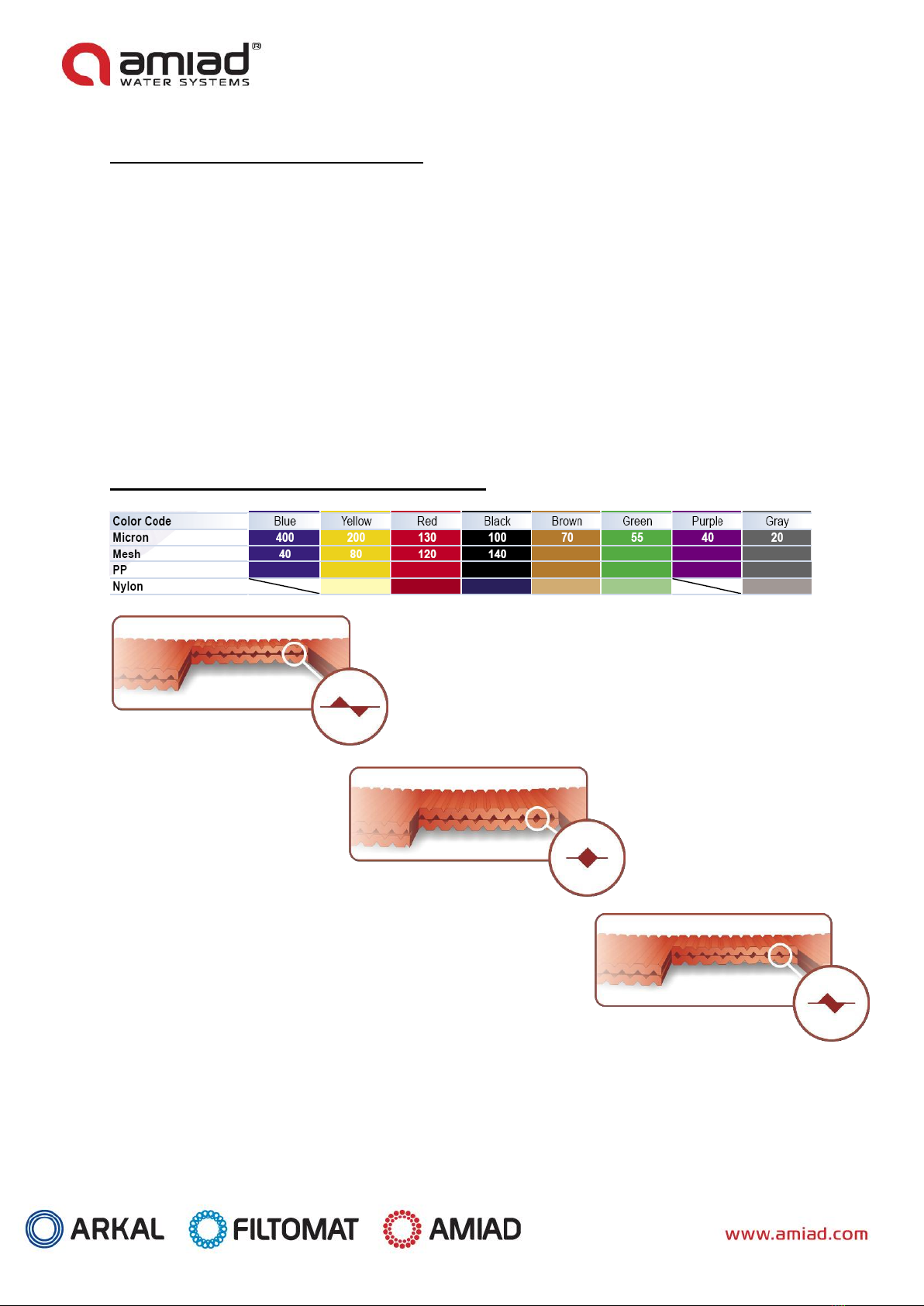
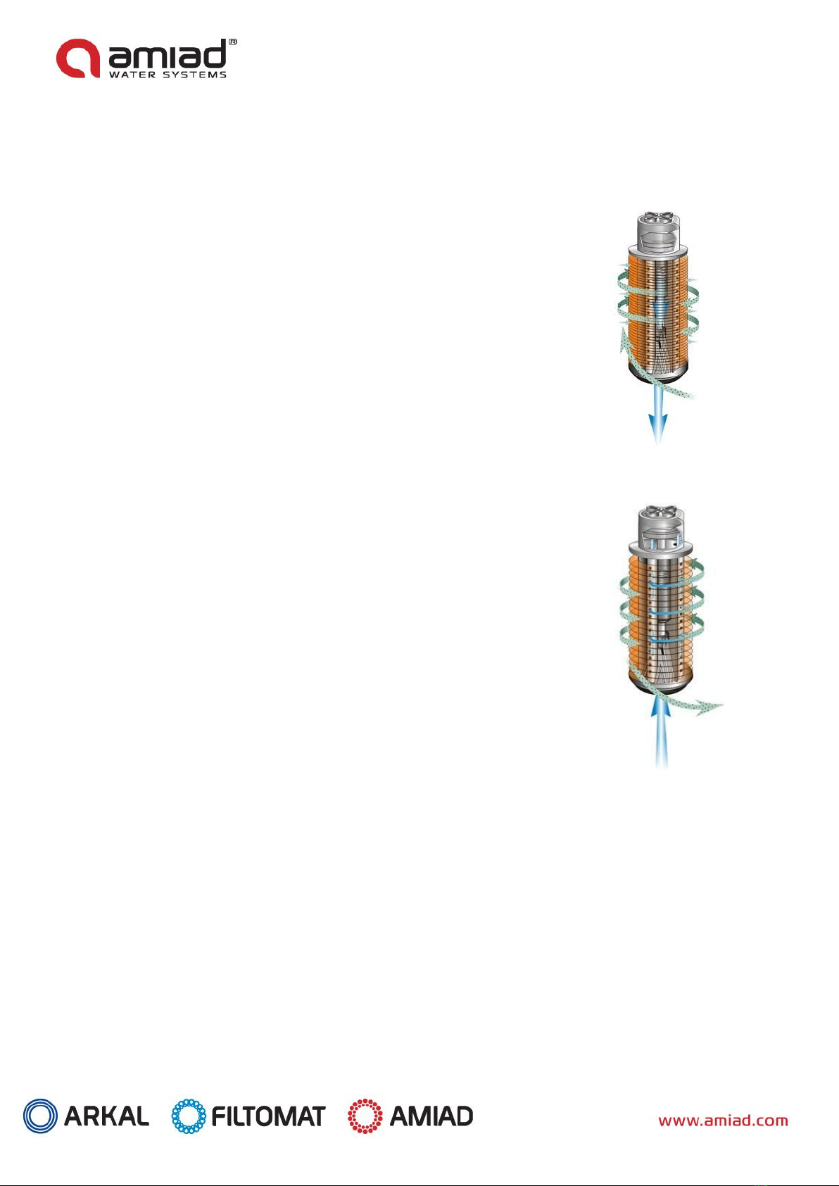
3.1 Disc Filtration Technology:.......................................................................................................7
3.2 Spin Klin Technology: .............................................................................................................. 8
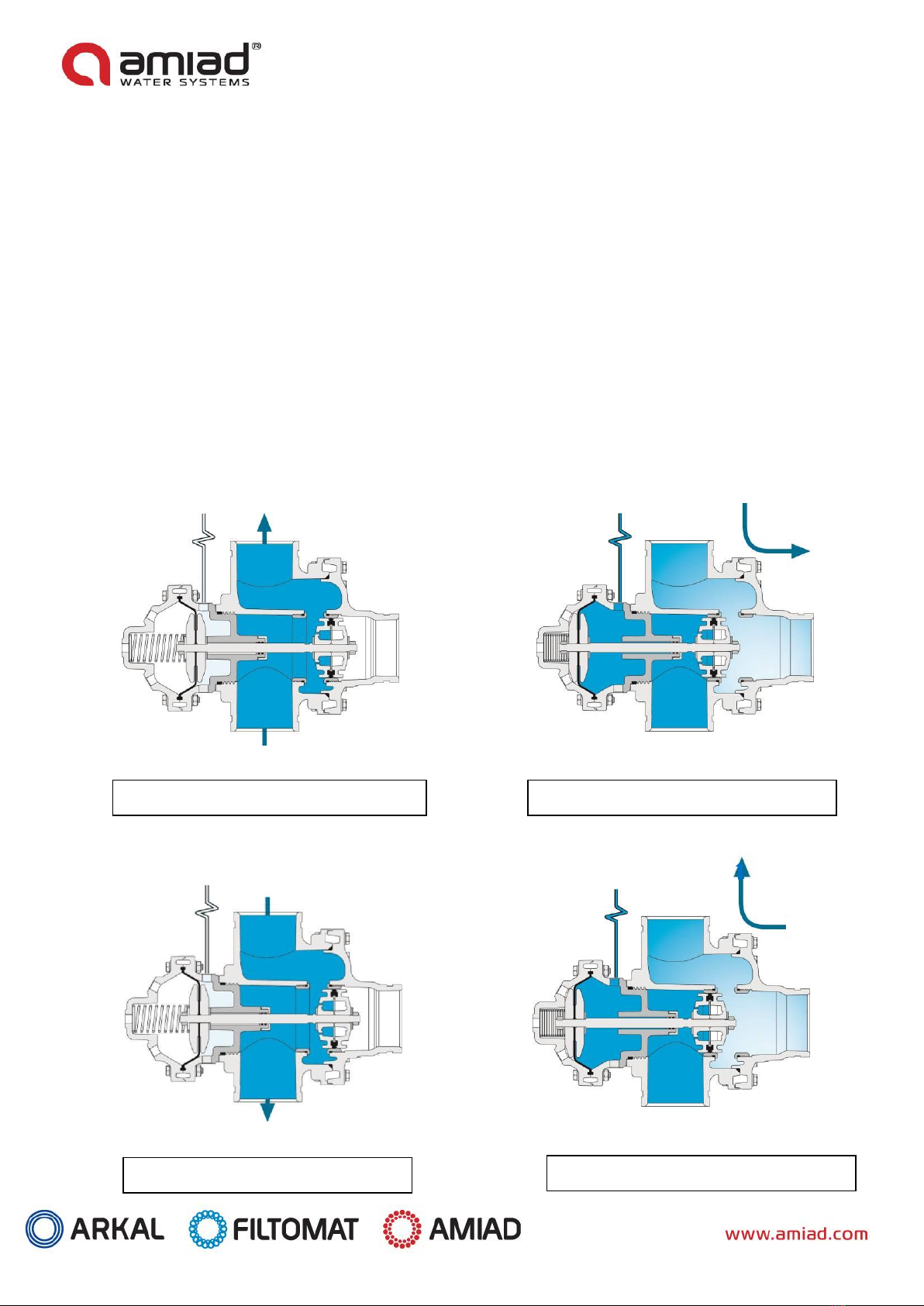
3.3 Back-flush Valves Operation Mode:..........................................................................................9
Filtration Process .................................................................................................................. 10
Back-flushing Process............................................................................................................ 10
4. Technical Data...................................................................................................................... 11
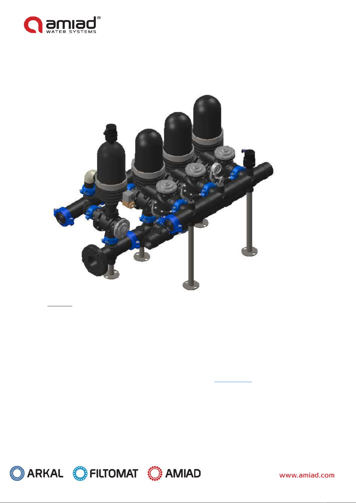
5. Dimensional Drawing............................................................................................................ 12
6. Installation & Start-up ......................................................................................................... 13
7. System Maintenance ............................................................................................................ 14
7.1 General inspection of the filter module operation:.................................................................. 14
7.2 Weekly maintenance:............................................................................................................ 14
7.3 Maintenance prior to long term cessation of filter operation: .................................................. 14
7.4 Maintenance prior to re-operation:........................................................................................ 14
7.5 Periodical: ............................................................................................................................ 15
7.6 Service & Opening the Filter Lid: ............................................................................................ 15
7.7 Cleaning Recommendations:.................................................................................................. 17
8. Troubleshooting ................................................................................................................... 19
9. Control Scheme .................................................................................................................... 21
11. FILTER PARTS SCHEDULE AND PARTS LIST............................................................................. 22
12. VALVES - PARTS SCHEDULE AND PARTS LIST ......................................................................... 23
12.1 STANDARD VALVES PARTS LIST ............................................................................................ 24
12.2 AW VALVES PARTS LIST........................................................................................................ 25
12.3 SW VALVES PARTS LIST ........................................................................................................ 26
13. SYSTEM DRAWINGS (to be amended per each specific ordered) ............................................ 27
14. AMIAD LIMITED WARRANTY ............................................................................................... 28

FILTER TYPE 2" AAF 000616-101019 /07.2017 Page 4of 28
1. Introduction
General:
Amiad Water Systems congratulates you on purchasing our new Arkal Spin Klin Filtration System.
All Arkal filters are easy to install, use and service and require no special skills to operate. For operation and
maintenance of this filter please follow the instructions in this manual. This Arkal Spin Klin battery system is an
automatic self-cleaning filter designed for non-hazardous liquids only and for operation within the pressure
framework described in the specifications table.
2. Safety Instructions
2.1 General Safety Instructions:
➢The manufacturer filtration products always operate as components in a larger system. It is essential for
the system designers, installers and operators to comply with all the relevant safety standards.
➢Prior to installation, operation, maintenance or any other type of action carried out on the filter, read
carefully the installation and operation instructions.
➢During installation, operation or maintenance of the filter all conventional safety instructions should be
observed in order to avoid danger to the workers, the public or to property in the vicinity.
➢The system has to be used for non-hazardous liquids only!
➢Please note: The filter enters into a flushing mode automatically, without prior warning.
➢No change or modification to the equipment is permitted without a written notification given by the
manufacturer or by its representative, on the manufacturer’s behalf.
➢Always observe standard safety instructions and good engineering practices whilst working in the filter’s
vicinity.
➢Use the filter only for its intended use as designed by the manufacturer, any misuse of the filter may lead
to undesired damage and may affect your warranty coverage. Please consult with the manufacturer prior
to any non-regular use of this equipment.
➢System's cleaning and maintenance shall be carried out only when explosive atmosphere is not present!
2.2 General Installation:
➢Install the filter according to the detailed Installation Instructions provided with the filter by the
manufacturer and according to the description given in this manual.
➢Make sure to leave enough clearance, side and top, so as to enable easy access for future treatments and
safe maintenance operations.
➢The user should arrange suitable lighting at the area of the filter to enable good visibility and safe
maintenance.
➢The user should arrange suitable platforms and safety barriers to enable easy and safe access to the filter
without climbing on pipes and other equipment. The user should verify that any platform, barrier, ladder
or other such equipment is built, installed and used in accordance with the relevant local authorized
standards.
➢Check and re-tighten all bolts during commissioning and after the first week of operation.
➢Use only appropriate standard tools and equipment operated by qualified operators when installing,
operating and maintaining the filter.
➢When installation is required in hazardous environment sites, underground or high above ground, make
sure that the site design and the auxiliary equipment are appropriate and that installation procedures are
carried out in accordance with the relevant standards and regulations.
➢Ensure walking areas about the installation are slip free when wet.

FILTER TYPE 2" AAF 000616-101019 /07.2017 Page 5of 28
2.3 Shipment and transporting:
➢Shipping and transporting the filter must be done in a safe and stable manner and in accordance with the
relevant standards and regulations.
➢For shipping, lifting and positioning the filter, use only approved lifting equipment and authorized
employees and contractors.
2.4 Electricity:
➢Electric wiring should be performed by an authorized electrician only, using standardized and approved
components.
➢The system must be installed with suitable electrical grounding that would prevent any electrostatic
discharge from the system.
➢Install a lockable main power cut-off switch close to the control panel.
➢If due to site constraints, the control panel is installed without a clear line-of sight of the filter, an
additional lockable power disconnect cut-off switch should be installed near each filter unit.
➢Installation of the filter should be performed so as to avoid direct water splashing on the electrical
components or on the control panel.
2.5 Pneumatics:
➢Install a lockable main cut-off switch, featured with a pressure release mechanism, on the compressed
air supply line close to the control panel.
➢If the control panel is installed far away and there is no eye contact with the filter, a lockable compressed
air cut-off switch, featured with a pressure release mechanism, should be installed near each filter unit.
➢The user should make sure that the compressed air supplied to the filter never exceeds the maximum
designated pressure for this filter. An air-pressure reduction valve should be installed on the compressed
air supply line upstream of the filter’s pneumatic inlet port.
2.6 Hydraulics:
➢Extra safety devices should be installed on hot water applications to avoid skin burn danger.
➢The user should install a manual Water Cut-off Valve next to the filter’s inlet port.
➢In cases where the downstream piping network downstream of the filter is pressurized an additional
manual Water Cut-off Valve should be installed next to the filter outlet port.
➢The user should make sure that the system includes a Pressure Release / Drainage Valve to enable
release of residual pressure prior to any maintenance procedure performed on the filter.
➢The user should make sure that the filter is never exposed to water pressure exceeding the maximum
designated pressure for this filter, if needed a Pressure Reduction Valve should be installed upstream of
the filter’s water inlet port.
➢Please note that the maximum working pressure indicated at the filter’s specifications table includes the
pressure caused by fluid hammer and pressure surge effects.

FILTER TYPE 2" AAF 000616-101019 /07.2017 Page 6of 28
2.7 Civil Engineering:
➢Make sure that the filter installation is done by the manufacturer qualified technicians.
➢Make sure that any civil engineering work at the installation site such as construction, lifting, welding,
etc. is done by qualified workers / technicians / contractors and in accordance with the relevant local
standards.
➢While using lifting equipment, make sure that the filter or the lifted part is chained securely and in
a safe manner.
➢Do not leave lifted equipment if there is no necessity. Avoid working below lifted equipment.
➢Wear a safety helmet while using lifting equipment.
➢Make sure that the flooring is sloped to for drainage and to avoid accumulation of liquids.
2.8 Commissioning:
➢Read carefully the Commissioning and the First Start-up Operation instructions prior to any attempt to
operate the filter.
➢In order to achieve maximum performance and smooth operation of the filter it is crucial to perform the
startup and first operation procedures exactly as described in this manual.
➢Commissioning the filter should be done by an authorized the manufacturer technician, do not attempt
to commission the filter unaccompanied since this may lead to undesired damage and may affect your
warranty coverage.
2.9 Operation and Control:
➢Do not operate the filter before reading carefully and being familiar with its operation instructions.
➢Observe the safety stickers on the filter and never perform any operation contradicting the instructions
given.
➢Never operate or use the filter for purposes other than its original design and operational envelope.
➢The system has to be used for non hazardous liquids only!
➢System's cleaning and maintenance shall be carried out only when explosive atmosphere is not present!
2.10 Maintenance:
➢Servicing the filter should be done only by technicians authorized by the manufacturer.
➢System's cleaning and maintenance shall be carried out only when explosive atmosphere is not present!
➢Disconnect the filter from the power supply and lock the Main Power Switch.
➢Disconnect the compressed air supply, release the residual pressure and lock the Pneumatics Main Valve.
➢Disconnect the filter from the water system by closing and securing the manual inlet valve. In cases
where the downstream piping network is pressurized, close and secure the manual outlet valve also.
➢Release the residual water pressure by opening the pressure release / drainage valve.
➢Empty the filter by opening the drainage valve.
➢In hot water systems wait till the filter components cool off to a safe temperature.
➢Place warning signs around the work area as required by the local standards and procedures.
➢Inspect the filter’s safety stickers and replace any damaged or faded sticker.
ATTENTION! - Before opening the filter lock, check that there is no pressure in the filter.

FILTER TYPE 2" AAF 000616-101019 /07.2017 Page 7of 28
3. Description & Operation
3.1 Disc Filtration Technology:
Amiad Filtration Systems uses a specially designed disc filtration technology. Thin, color-coded polymeric discs
are diagonally grooved on both sides to a specific micron size. A series of these discs are then stacked and
compressed on a specially designed spine. When stacked, the groove on top runs opposite to the groove below,
creating a filtration element with a statistically significant series of grooves and traps for solids. The stack is
enclosed in corrosion and pressure resistant housing.
During the filtration process, the filtration discs are tightly compressed together by the spring’s power and
the differential pressure, thus providing high filtration efficiency. Filtration occurs while water is percolated from
the outer diameter to the inner diameter of the element. Depending on the micron rating, there are from 18 (in
400 micron discs) to 32 (in 20 micron discs) stopping points in each track, thus creating the unique in-depth
filtration.
Table of Filtration Grades of the Discs and Color Code

FILTER TYPE 2" AAF 000616-101019 /07.2017 Page 8of 28
3.2 Spin Klin Technology:
Spin Klin Spine - The Core of the Spin Klin Filtration System
The Spin Klin discs are stacked on the Spin Klin
Spine.
The
discs are color-coded
according to micron size, and are assembled to suit your water filtration
requirements. The spine assembly has a spring compression unit and an internal
Piston, which operate during alternate filtration or back-flush modes. Inside the
housing a spring and the
pressure
difference compress the discs tightly during the
filtration process, forcing the water to flow between the grooves on the discs and
trap
the
solids.
Spin Klin Automatic Back-flush Operation
Activated by an external command
(differ
ential pressure or time) alternate units of
the Spin Klinsystem go
into
back-flush
mode.
During the back-flush mode, the compression spring is released and the pressure
difference is
eliminated
.The spine piston rises up, releasing the pressure on the discs.
Tangential jets of clean water are sprayed at high pressure through the nozzles of the
spine at the discs. The discs spin freely loosening the trapped solids that quickly and
efficiently washed out through the drain.

FILTER TYPE 2" AAF 000616-101019 /07.2017 Page 9of 28
3.3 Back-flush Valves Operation Mode:
Modes of the filter’s Control valve
Filtration Position:
•Inlet valve - Water flows from port [2] (main supply) to port [C] (filter connection). Port [1] (drain water
outlet) is closed by the seal.
•Outlet valve - Water flows from port [C] to port [2]. Port [1] is closed by the seal.
Back-flush Position:
•Inlet valve - Command pressure is applied to the diaphragm’s control chamber through port [D]. The
diaphragm moves the sealed shaft, port [2] closes, preventing flow to the filter. Port [C] opens, allowing
flushing water to flow from port [C] (filter connection) to the drain [1].
•Outlet valve - Command pressure is applied to the diaphragm’s control chamber through port [D]. The
diaphragm moves the sealed shaft, port [2] closes, port [1] opens, allowing flushing water to flow to port [C].
1
D
2
C
D
2
C
1
Inlet Valve Filtration Mode
D
2
C
1
Inlet Valve Back-flush Mode
D
2
C
1
Outlet Valve Back-flush Mode
Outlet Valve Filtration Mode

FILTER TYPE 2" AAF 000616-101019 /07.2017 Page 10 of 28
3.4 Mode of Operation
Filtration Process
•During the filtration stage water flows through the Inlet Manifold, distributing through the Straight flow
Valve to the 2" Spin Klin Filter.
•The water passes through the Filters Filtration Elements Cleaned and flows out through the Straight flow
Valve to the Outlet Manifold and to the customer.
•At this stage the Accumulator Tank fills up with clean water from the Outlet Manifold through its Check
Valve.
Back-flushing Process
1. The Controller/PLC transmits an electric signal to solenoid No.1 (as per pressure differential set point
reach, time set-up or manually whichever comes first).
2. Command from solenoid No. 1 simultaneously flow to the valves of filter No.1:
a. To the INLET VALVE (Straight Flow) converting it from filtration mode to back-flush mode.
b. To the OUTLET VALVE (Straight Reverse Flow) converting it from filtration mode to back-flush
mode.
3. After Pre-set Valve delay time the Controller/PLC transmits an electric signal to the Valve Delay
Solenoid.
4. Command from the Valve delay solenoid simultaneously flow to the Accumulator Tank valves:
a. To the Air Valve, allowing the compressed Air to enter the Accumulator Tank.
b. To the Check Valve to close the connection to the outlet manifold.
5. The Compressed Air enters the Accumulator Tank and increase the water pressure in it to the pressure
of the Compressed Air.
6. The Air is mixed with clean water and is carried to Filter No.1 which is then Back-flushed.
*The ratio between Air and water will rise until there is hardly any water at termination (air alone does
not spin the discs).
7. At the end time of the Back-flush the Controller/PLC release the command first of the Valve delay
Solenoid then after the same delay time as paragraph 3 to the Solenoid No.1.
8. The Accumulator Tank need to fill up with clean water before the next filter can be back-flushed, about
20 –25 second will be enough.
9. When the Accumulator Tank is filled up the controller will start back-flush the next filter until all the
filters are clean.

FILTER TYPE 2" AAF 000616-101019 /07.2017 Page 11 of 28
4. Technical Data
Parameters
METRIC
US
Maximum pressure
10 bar (25C)
145 psi ( 77 °F)
Minimum working pressure
Minimum pressure for back-flush:
400µ-130µ
100µ-70µ
50µ-20µ
1.0 bar
3 bar
3.5 bar
5 bar
14.5 psi
43.5 psi
50.75 psi
72.5 psi
Back-flush water volume
12 –22 (L)
Per single filter
3.2 –5.8 (Gl)
Per single filter
Maximum temperature
60 °C (@4 bar )
158 °F (@58 psi)
PH
4-11
4-11
Air Pressure
Equal or higher than the
pressure used for back-
flush.
Equal or higher than
the pressure used for
back-flush.
Construction Materials
Filter Housing & Lid
RPA (Reinforce Polyamide) or RPP (Reinforce Polypropylene)
Disc elements
PP (Polypropylene) or PA (Polyamide)
Backwash valves
RPA (Reinforce Polyamide) or RPP (Reinforce Polypropylene)
Manifolds
PP (Polypropylene)
Seals
NBR or EPDM, (Viton optional)
Control Tubing
PE or PA
Recommendation Air Compressor: 3/4 H.P. + 80L /21Gl Tank.

FILTER TYPE 2" AAF 000616-101019 /07.2017 Page 12 of 28
5. Dimensional Drawing
Description
Length
Height
Width
2-unit battery
840
1128
868
3-unit battery
1140
1128
868
4-unit battery
1440
1128
868
5-unit battery
1,740
1128
868
6-unit battery
2,040
1128
868
7-unit battery
2,340
1,178
921
8-unit battery
2,640
1,178
921

FILTER TYPE 2" AAF 000616-101019 /07.2017 Page 13 of 28
6. Installation & Start-up
Installation
A. Check for any transport damage (The System operates under pressure!).
B. Make sure that the inlet and outlet orientations are correct (shown by arrows on The System).
C. Connect the Inlet, Outlet, Drain with theirs valves to the Main manifolds.
D. Verify that all the covers clamps are properly closed !.
E. Connect and check the pressure source to the command solenoids of the PLC/Controller.
F. Connect the Air pressure source to the Accumulator.
Start-up Operation
•If possible do a dry test run (once or more) on all the system to be sure all connections and wiring are
ok.
•Run the System by slowly open the inlet valve letting the Air from the system to vent out from the Air
Release Valve on top of the Inlet manifold.
•Once the Air vents, check for leakages that can happen during transportation and installation.
•If the pressure difference is high, verify that the flow rate is not too high. An excessive flow rate
through the filter causes excessive pressure loss.
•Open the Air supply and check the Air pressure in the Accumulator tank.
•Manually Start a back-flush cycle and make sure that all system components function correctly.
•If after the Back-flush the pressure difference is not reduced check if the flow is not too high, or the Air
supply is too low (pressure/flow).
Note: PLC/Controllers are varied according to the Order.
PLC/Control
•Refer to the manufacturer’s handbook before installing the PLC/Controller.
•Make sure that the voltage is correct BEFORE connecting it.
•Check that the ∆P hydraulic switch HIGH and LOW pressure tubes are correctly connected to the
appropriate ports.
•Set the DP switch to the required ∆P (Recommended ∆P will be 5m/ 7PSI according to the site
conditions).
•Set the PLC/Controller Back-flush Time to 7 seconds, Valve Delay to 1 second and the Dwell time to 25
seconds. These settings may require adjustment to conform to local water conditions. Typically, a 1 to
3 hour interval between back-flushes cycles is recommended.
•Typically the Back-flush Cycle Time is a backup for the DP switch, it work in a way that whichever come
first reset the back-flush Cycle Timer.(Manual override will reset it too).

FILTER TYPE 2" AAF 000616-101019 /07.2017 Page 14 of 28
7. System Maintenance
General:
Before beginning any maintenance procedure, carefully read the safety & instructions in this document, make
sure that all the workers at the filtration site are fully aware and comply with the safety instructions, these and
any other local safety instructions.
7.1 General inspection of the filter module operation:
This is the visual basic general inspection procedure of the filter for proper operation. It should be done
regularly and prior to any scheduled maintenance procedure.
Initiate a self-cleaning cycle and inspect the filters of the system for proper operation.
7.2 Weekly maintenance:
Visual Check:
A. Check that the system operates properly by following the General Inspection of the Filter Operation as
described above.
B. Visually check the filter housing for leakage.
C. Check the system for loosen bolts.
7.3 Maintenance prior to long term cessation of filter operation:
The following must be done if the system will not be operated for more than two weeks.
A. Run a Back-flushing cycle.
B. Release pressure from the filter system with the ball valve on the outlet manifold.
C. Close and release the Air pressure from the Accumulator tank.
D. Do a dry back wash (no water in the system, no Air supply to the accumulator).
E. Close and disconnect the Air supply to the controller.
7.4 Maintenance prior to re-operation:
A. Reconnect the system to the water and air supply, attach and open the air supply to the controller.
B. Run a back-flush cycle, Check proper operation of the system.

FILTER TYPE 2" AAF 000616-101019 /07.2017 Page 15 of 28
7.5 Periodical:
Before beginning any maintenance procedure, carefully read the safety & instructions in this document, make
sure that all the workers at the filtration site are fully aware and comply with the safety instructions, these and
any other local safety instructions.
1. Perform a General Inspection of the system operation as described above and carefully inspect the filter
visually for:
•Proper operation
•Any leakage from the filter housing or accessories
•Abnormal or unusual noises
•Loosen bolts
•Any sign of corrosion on the filter housing or accessories
•Unusual vibrations
•Non-smooth operation of the filter air release valves and drainage ball valves.
2. Drain the system and release any water and pressure left in it.
3. Disassemble the filter’s lids (As described in chapter 'Open the Filter for Service' in this document)
4. Inspect the filter internal components and seal for any wear and tear
5. Check the filter housing and lid for any sign of mechanical damage
6. Replace any damaged component
7. Make sure that your maintenance engineers are aware of even the slightest sign of damage to the filter
housing, lid or accessories. In such case, please contact your Amiad representative immediately.
8. Re-assemble the filter’s lids (As described in chapter 'Open the Filter for Service' in this document)
9. Perform a complete COMMISSIONING, START-UP AND FIRST OPERATION as described earlier in this
document.
7.6 Service & Opening the Filter Lid:
Before beginning any maintenance procedure, carefully read the safety & instructions in this document,
make sure that all the workers at the filtration site are fully aware and comply with the safety instructions,
these and any other local safety instructions.
Tools & Accessories needed:
•Socket Wrench 1/2"
•Torque Meter Wrench set to 70 N-m
•Amiad Spin Klin Butterfly Nut Socket/Wrench
•Amiad Spin Klin Filtration Element Socket
•Silicon Grease

FILTER TYPE 2" AAF 000616-101019 /07.2017 Page 16 of 28
Preparations:
•Disconnect the system from the water supply and drain it via its 3/4" ball valve, live the valve open.
•Perform a general inspection of the system.
1. Re-Check that the system is not
under pressure!
2. Carefully release the clamp and
remove the lid. (Figure.1)
3. Unscrew the butterfly-nut on the
filtration element. (Figure.2)
4. Remove the tightening cylinder.
(Figure.3)
5. Remove the discs (for convenience
we recommend using a plastic
bag) (Figure 4, 5)
6. Tie each set on a string and place
them in a cleaning solutions (refer
to 'Cleaning Recommendations' in
this Document)
7. Thoroughly wash the discs with
fresh water and then reassemble
each set of discs on its spine
(Figure 6).
8. Check that the correct quantities
of discs are assembled on the
spine (Figure.7)
9. Put on the tightening cylinder and
tighten the butterfly-nut. (Figure
8, 9)
10. Reassemble the filter lid and
tighten the clamp. (Figure 10, 11)
Figure 7
Figure 8
Figure 9
Figure 10
Figure 11
Figure 4
Figure 5
Figure 6
Figure 1
Figure2
Figure 3

FILTER TYPE 2" AAF 000616-101019 /07.2017 Page 17 of 28
7.7 Cleaning Recommendations:
Cause for clogged Filtration Discs:
Water-formed deposits may cause clogging of the Filtration discs. The formation of these deposits
depends on the quality of the water source and environmental conditions like temperature, pH, light,
duration of filtration and more.
Common water-formed deposits are:
•Biological or organic deposits (mostly mucous or oily to the touch, beige, brown or green in color)
•Iron oxide (rust) or other metal oxides
•Carbonates (white or gray deposit)
•Combinations of the above
If these deposits cannot be eliminated by pretreatment of the water, we recommend the following
cleaning procedure:
Material and Equipment:
•A well-ventilated working place.
•2 small containers (1 liter), 2 large containers (15 liter) and a stirring stick, all resistant to chemicals,
preferably of polypropylene.
•Plastic rope to tie up the disc.
•Sodium Hypochlorite NaOCl - Strong oxidizing liquid, commercial concentration: 10%. Oxidizes and
removes organic and biological deposits.
•Hydrochloric Acid HCl - Very corrosive liquid, commercial concentration: 30%. Dissolves and removes
carbonates, iron oxide, and other deposits.
•Safety equipment: safety glasses, gloves, long pants, long sleeved shirt and shoes.
ATTENTION !
While working with chemicals protect yourself with the necessary safety equipment:
•Safety glasses, gloves, protective clothing
•Work in a well-ventilated area
•Follow the manufacturer’s instructions
Cleaning Organic and Biological Deposits:
•Open the filter and remove dirty discs.
•Attention –Never open the filter before the pressure has been released.
•Arrange the discs loosely on the plastic rope.
•Prepare a 5% Sodium Hypochlorite solution: pour 5 liters of water into one of the large containers add 5
liters of Sodium Hypochlorite (10%) into the water.
•Soak the discs in the solution so that both sides are covered. To achieve maximum cleaning, agitate the
discs several times with a stirring stick.
•Contact time with cleaning solution: up to 8 hours.
•Remove the discs carefully from the solution, put them in the second large container and rinse them
very well with clean water before placing them back in the filter.
•The recommendation is to wash the cleaned discs again in the filter to ensure that all chemical residues
ware removed.

FILTER TYPE 2" AAF 000616-101019 /07.2017 Page 18 of 28
•The cleaning solution can be used for several sets of discs. As the cleaning activity of the solution
deteriorates, it may be necessary to soak the discs for a longer time
Cleaning Carbonates and Iron Deposits:
•Open the filter and remove the dirty discs.
•Attention –Never open the filter before the pressure has been released.
•Arrange the discs loosely on the plastic rope.
•Prepare a 5% Solution of Hydrochloric Acid: pour 10 liters of water into one of the large containers
carefully add 2 liters of Hydrochloric Acid (30%) into the water.
•Soak the discs in the solution so that both sides will be covered.
•NOTE: Carbonates react violently with hydrochloric acid (foaming, gas evolution).
•To achieve maximum cleaning, agitate the discs several times with a stirring stick.
•Contact time with cleaning solution: 1 - 8 hours.
•Remove the discs carefully from the solution and rinse them well with clean water before placing them
back in the filter.
•The recommendation is to wash the cleaned discs again in the filter to ensure that all chemical residues
ware removed.
•The cleaning solution can be used for several sets of discs. It may be necessary to soak the discs for a
longer period of time as the cleaning activity of the solution deteriorates.
Cleaning Complex Deposits:
If the composition of the deposit is not known, perform the following test:
•Take 5 discs for the test.
•Soak 2 discs in a 5% Sodium Hypochlorite Solution.
•Preparation of the solution: pour 1 cup of water into a small container, then add 1 cup of Sodium
Hypochlorite (10% NaOCl).
•Soak 2 discs in a 5% Hydrochloric Acid Solution.
•Preparation of the solution: pour 2½ cups (= 500ml) of water into a small container, then add carefully
•½ cup (= 100ml) of Hydrochloric Acid (30% HCL).
•Keep one disc as a control.
•Observe the cleaning process: If one of the solutions removes all of the deposit, clean the discs in that
solution according to the instructions above.
•If neither solution removes the deposit completely, continue with the test procedure.
•Remove the discs from both solutions, Wash them with running water and soak them in the second
solution: put the two discs, which have been in the Sodium Hypochlorite Solution, in the
Hydrochloric Acid Solution, and the other way around.
•Check the cleaning process: If one of the treatments removes all of the deposit, clean all of the discs
following the same two-step procedure in the exact same order. Wash the discs well between the two
cleaning processes.
•If the deposit hasn’t been completely removed, send a set of untreated discs to the laboratory for
further examination.

FILTER TYPE 2" AAF 000616-101019 /07.2017 Page 19 of 28
8. Troubleshooting

FILTER TYPE 2" AAF 000616-101019 /07.2017 Page 20 of 28
Table of contents
Other amiad Industrial Equipment manuals
Popular Industrial Equipment manuals by other brands

A-PLUS AUTOMATION
A-PLUS AUTOMATION A44-P Instruction handbook

Rexnord
Rexnord Falk GL20 Installation and Maintenance

Lincoln
Lincoln Quicklub SSV L user manual

INOXPA
INOXPA HYGINOX Ex SE Installation, service and maintenance instructions

Eaton
Eaton NZM4-XU Series Instruction leaflet

Parker
Parker Phastite PH-8-HANDTOOL Assembly instructions

HALDER
HALDER M8 Short instruction manual

Texas Automation Products
Texas Automation Products DES-32 manual

Siemens
Siemens Simatic S7-1500/ET 200MP Compact operating instructions

PI
PI L-417.**9211E1B Series user manual

Fluke
Fluke PRUFTECHNIK ROTALIGN touchEX manual

Huawei
Huawei FDT2108D-288 Quick installation guide