Erskine Attachments V-Plow User manual

V-Plow
For
Skid Steer Loaders
Operator’s Manual
Maintenance
Parts Information
Read this Manual Before Use

2
TABLE OF CONTENTS
REFERENCE INFORMATION
Write the serial number for your attachment in the spaces below. Always refer to this serial
number when calling for service or parts.
Serial Number………….._____________
YOUR ATTACHMENT DEALER
ADDRESS:
PHONE:
CONTACT:
SAFETY
3-4
SERIAL NUMBER/DECAL LOCATION
5-6
USER’S MOUNTING INSTRUCTIONS
7-8
OPERATING INSTRUCTIONS
9
ROUTINE MAINTENANCE
10-11
PARTS INFORMATION
12-15
GENERAL SPECIFICATIONS
16
BOLT TORQUE INFORMATION
17
NOTES
18
WARRANTY
19
NOTE: Erskine Attachments LLC reserves the right to make
improvements in design or changes in specifications at any time without
notice and without incurring any obligations to install them on units
previously sold.

3
The signal words CAUTION, WARNING, or
DANGER are used to indicate hazards.
Indicates a potentially
hazardous situation which, if not avoided,
may result in minor or moderate injury.
Indicates a potentially
hazardous situation which, if not avoided,
could result in death or serious injury.
Indicates a potentially
hazardous situation which, if not avoided,
will result in death or serious injury.
The word IMPORTANT is used in the text when
immediate damage will occur due to improper
technique or operation.
The word NOTE is used to convey information that
is out of context with the manual text; special
information such as specifications, techniques,
reference information, and other information of a
supplementary nature.
The user is responsible for inspecting the machine
daily, and for having parts repaired or replaced when
continued use of the machine would cause damage,
excessive wear to other parts or make the machine
unsafe for continued operation.
If an operating procedure, tool device, maintenance
or work method not specifically recommended is
used, you must satisfy yourself that it is safe for you
and others. You must also ensure that the
attachment will not be damaged or made unsafe by
the procedures you choose.
Erskine Attachments LLC cannot anticipate every
possible circumstance that might involve potential
hazard. The safety messages found in this manual
and on the machine are therefore not all inclusive.
Throughout this manual, reference may be made to
the left hand (LH) and right hand (RH) side. These
terms are used as viewed from the operator’s seat
facing front.
SAFETY
DO NOT use or perform maintenance on this machine until this manual has been
read and understood. In addition, read the Operation and Maintenance
Manual(s) pertaining to the attachment and the attachment carrier (“Loader”).

4
SAFETY
Improper operation can cause serious
injury or death.
Pre-operation
•This machine is designed for moving snow only.
NEVER use this machine for any other purpose.
•Read the operator’s manual for the “Skid Steer
Loader.”NEVER allow untrained people to
operate.
•Operating instructions must be given to everyone
before operating this attachment and at least once
a year thereafter in accordance with OSHA
regulations.
•NEVER exceed the maximum recommended input
power or speed specifications for the attachment.
Over-powering or over-speeding the attachment
may cause personal injury and/or machine
damage.
•Keep all shields, guards, and covers in place.
•Do not modify equipment or add attachments that
are not approved by Erskine Attachments LLC.
•Use adequate safety warning lights and devices as
required by local regulations. Obey all local laws
and regulations regarding machine operation on
public property.
Operation
•Hydraulic connections may be hot after use. Use
gloves if connecting or disconnecting after use.
•Check and be sure all operating controls are in
neutral before starting the engine.
•Keep people away from loader and attachment
when in use. This attachment has moving parts.
•Always stay in the operator’s position when using
the attachment.
Operation (continued)
•NEVER operate near embankments or terrain that
is so steep that rollover could occur.
•Before leaving the operator’s position, lower the
attachment to rest flat on the ground, stop engine,
relieve hydraulic pressure to the attachment, set
park brake, and wait for all motion to stop.
•NEVER place hands near moving parts or clear
debris while engine is running.
Avoid High Pressure Fluids Hazard
•Escaping fluid under pressure can
penetrate the skin causing serious
injury.
•Avoid the hazard by relieving the
pressure before disconnecting
hydraulic lines.
•Use a piece of paper or cardboard, NOT BODY
PARTS, to check for suspected leaks. Wear
protective gloves and safety glasses or goggles
when servicing or performing maintenance on
hydraulic systems.
•If an accident occurs, see a doctor immediately.
Any fluid injected into the skin must be surgically
removed within a few hours or gangrene may
result.
Maintenance
•NEVER make adjustments, lubricate, clean, or
perform any service on the machine while it is in
operation.
•Make sure the attachment is serviced on a daily
basis. Improper maintenance can cause serious
injury or death in addition to damage to the
attachment and/or your equipment.

5
SERIAL NUMBER AND SAFETY DECAL LOCATIONS
Serial Number Location:
It is important to refer to the serial number of the attachment when making repairs or ordering parts. Early or later
models (identification made by serial number) may use different parts, or it may be necessary to use different
procedures in doing a specific operation.

6
Part number: 200001
Location: On top of pivot frame
Quantity: 1
Part number: 203234
Location: On each side of pivot frame
Quantity: 2
SERIAL NUMBER AND SAFETY DECAL LOCATIONS________
Small Brand Decal
Location: On back of moldboard, both ends
Quantity: 2
Safety Decals Locations:
The locations of the safety decals are shown. If
these decals are missing, damaged, or painted over
they must be replaced. Call Erskine Attachments
LLC (218-435-4045) for replacement decals.
B
A
C
D
Part number: 320025
Location: On each side of mount frame
Quantity: 2
Part number: 300245 (Yellow Reflector)
Location: On back of moldboard, both ends
Quantity: 2
E
Part number: 202153 (Tape Anti-Skid 2 x 16)
Location: Top of pivot frame & mount frame
Quantity: 2
F
Part number: 202152 (Tape Anti-Skid 2 x 8)
Location: On top of pivot frame
Quantity: 1

7
USER’S MOUNTING INSTRUCTIONS
After the initial set-up assembly is completed, use the following procedure to mount the attachment to the loader.
Coupler wedges or pins must extend through holes in attachment. Levers must be fully
down and locked. Failure to secure wedges or pins can allow the attachment to come off and cause injury
or death.
1. Use the step, safety treads, and grab handles to
get on and off the loader and attachment.
2. Sitting in the operator’s seat, lower seat bar (if so
equipped) and fasten the seat belt.
3. Drive the loader to the rear of the attachment. Put
the loader quick attach coupler into theattachment
mounting bracket.
4. Tilt the loader coupler backward a small amount
until it is fully engaged in the attachment mounting
bracket.
5. Stop the engine and engage the park brake.
6. Secure the coupler locking mechanism that
attaches the attachment to the loader.

8
USER’S MOUNTING INSTRUCTIONS
7. Connect the hydraulic quick couplers from the
attachment to the loader.
IMPORTANT: Wipe the ends of the hydraulic
quick couplers (both lead and loader) with a rag
to remove any possible contamination.
Contamination can cause hydraulic components
to fail and is not covered under warranty.
IMPORTANT: Make sure the quick couplers are
fully engaged. If the quick couplers do not fully
engage, check to see that the couplers are the
same size and brand. Do not force the quick
couplers together.
NOTE: See the loader’s operator’s manual for
auxiliary hydraulic specifications and connection
instructions.
NOTE: Attachment is shipped with 8FJX (1/2”
Female JIC Swivel) fittings on the ends of the
lead hoses.
8. Make sure the hoses are properly routed to fit
your specific loader. If the hoses are not routed
correctly, hoses may get pinched or rub on tires.
Be sure to check the hose routing through the full
range of intended motion of the attachment
before operating it.
More than one routing may be acceptable
depending on the loader. Pick the routing that
best suits your loader.
IMPORTANT: Proper hose routing is the
responsibility of the owner and/or operator.
Pinched or stretched hoses are not covered
under warranty.
Mounting is now complete and the attachment is
ready for operation. Use reverse order of above
instructions to dismount the attachment from the
loader.

9
OPERATING INSTRUCTIONS
V
Straight
Scoop
Angle Right
Angle Left
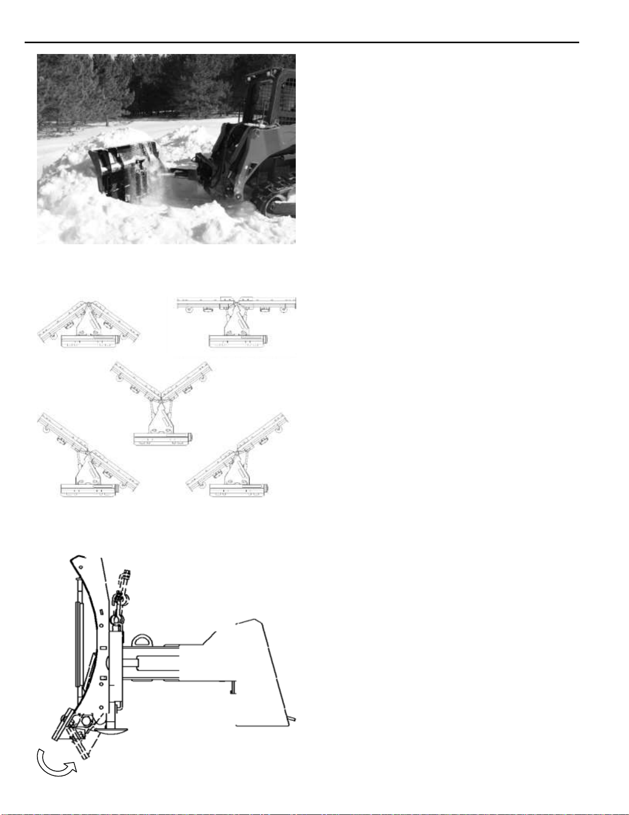
IMPORTANT: The v-plow is designed for snow
removal only. It is not designed for moving or grading
soil.
1. With the operator in the seat of the loader, the seat
belt fastened, and the seat bar lowered (if so
equipped), start the engine.
2. With the loader lift arms fully lowered, tilt the
attachment forward to rest on the skid shoes.
3. Drive the loader forward to push snow.
4. Use the loader lift and tilt functions to increase
traction and adjust the pitch of the v-plow.
Blade Angle
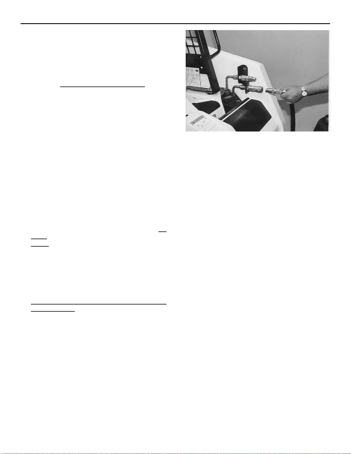
The v-plow utilizes a specially designed valve block to
change the blade orientation without the requirement
of an electrical attachment control system. The valve
block isolates one side of the attachment as the
priority side, with the secondary side moving once the
priority side has reached the end of its stroke.
1. Activate the auxiliary hydraulic circuit to move the
priority side to the desired position and keep it
activated until the secondary side has moved to
the desired configuration.
2. To move the blades into a position other than the
end of the stroke, activate the auxiliary hydraulic
circuit until the secondary side is in the desired
position, then reverse the hydraulic flow until the
priority side in in the desired position.
NOTE: The blades may have to be repositioned after
hard contact with a solid object. This is normal due to
the design of the valve block.
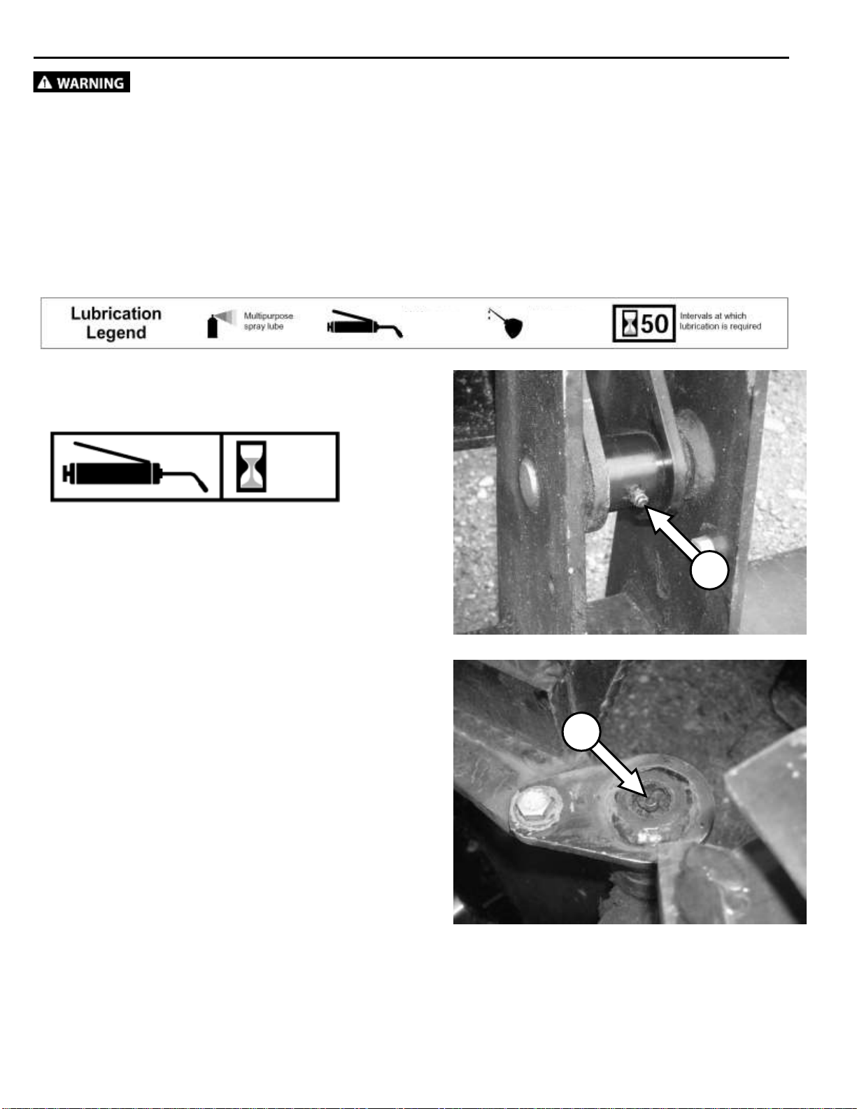
Trip Springs
The v-plow is equipped with trip springs which allow
the cutting edge to trip when it strikes an obstruction.
This helps to protect the attachment and the
obstruction from damage.
To reset the trip springs after striking an obstruction,
raise the loader lift arms to lift the attachment slightly
off of the ground, or slowly drive the loader backward
a few feet.

10
ROUTINE MAINTENANCE
Lower the attachment to rest flat on the ground, shut down the engine, relieve the
hydraulic pressure to the attachment, set the park brake, and wait for all motion to stop before leaving
the operator’s seat to perform service of any kind.
It is the operator’s responsibility to make daily inspections of the loader and attachment for damage, loose bolts,
fluid leaks, or anything else that could cause a potential service or safety problem. Preventive maintenance is
the easiest and least expensive type of maintenance.
IMPORTANT: Bolts can loosen after initial usage. After the first hour of operation check all bolts.
A
B
Use No. 2 lithium base gun grease when lubricating
all attachment grease fittings.
Grease both mounting plate pivot bushings [A] every
8 hours of operation.
Grease the blade pivot pins (top and bottom) [B]
every 8 hours of operation.
8
No. 2 Lithium
base gun grease
Clean engine oil
LUBRICATION

11
ROUTINE MAINTENANCE
C
C
D
E
Grease all four cylinder bushings [C] every 8 hours
of operation.
Skid Shoe Height Adjustment
1. Raise the v-plow off of the ground and block up
securely.
2. Remove the lynch pin [D] from the first skid shoe
and slide the skid shoe out of the mount bushing.
3. Install spacer washers [E] on the skid shoe to
achieve the desired cutting edge height, and slide
the skid shoe back into the mount bushing.
4. Store remaining spacer washers on top of the
mount bushing, an install the lynch pin to secure
the skid shoe and washers in place.
5. Repeat steps 2-4 for the other skid shoe. Make
sure both skid shoes are set to the same height.
8

12
PARTS INFORMATION
ITEM
QTY
PART NO.
DESCRIPTION
STOCK NO.
1
1
311300
MOUNT V-PLOW W/A
1
422197
MOUNT V-PLOW MULTIHOG W/A
MULTIHOG MOUNT
2
1
311379
MOLDBOARD V-PLOW 84 LH W/A
USED ON 84”
1
311381
MOLDBOARD V-PLOW 96 LH W/A
USED ON 96”
1
311383
MOLDBOARD V-PLOW 108 LH W/A
USED ON 108”
3
1
311380
MOLDBOARD V-PLOW 84 RH W/A
USED ON 84”
1
311382
MOLDBOARD V-PLOW 96 RH W/A
USED ON 96”
1
311384
MOLDBOARD V-PLOW 108 RH W/A
USED ON 108”
4
2
311305
SPRING LIFT W/A
5
4
100303
SPRING TRIP 2.38 OD X 15 EXT
6
1
311301
PIVOT MOUNT W/A
8
1
311304
TRIP EDGE 84 W/A
USED ON 84”
1
300879
TRIP EDGE 96 LH W/A
USED ON 96”
1
300881
TRIP EDGE 108 LH W/A
USED ON 108”
9
1
311304
TRIP EDGE 84 W/A
USED ON 84”
1
300880
TRIP EDGE 96 RH W/A
USED ON 96”
1
300882
TRIP EDGE 108 RH W/A
USED ON 108”
10
2
311306
PIN 1.25 X 6 GREASABLE W/A
12
2
400041
PIN 1 X 4 W/A
13
6
13467
BOLT HEX 1 X 3-1/2 NC GR 5
USED ON 84”
8
13467
BOLT HEX 1 X 3-1/2 NC GR 5
USED ON 96 & 108”
14
2
37217
NUT HEX LOCK
3/4 NC
16
8
103116
BOLT HEX
3/8 X 1 NC GR 5
17
12
37212
NUT HEX LOCK
3/8 NC
18
8
201452
BOLT CARRIAGE 5/8 X 1 1/2 NC GR 5
USED ON 84”
10
201452
BOLT CARRIAGE 5/8 X 1 1/2 NC GR 5
USED ON 96 & 108”
19
12
37216
NUT HEX LOCK 5/8 NC
USED ON 84”
14
37216
NUT HEX LOCK 5/8 NC
USED ON 96 & 108”
20
2
100301
SKID SHOE
22
6
37219
NUT HEX LOCK 1 NC
USED ON 84”
8
37219
NUT HEX LOCK 1 NC
USED ON 96 & 108”
24
2
311362
BRKT SPRING LIFT HOLDER PAINTED
25
4
42264
BOLT EYE 1/2 X 4
26
2
311367
CUTTING EDGE B 1/2 X 6 X 38.56
USED ON 84”
2
311368
CUTTING EDGE B 1/2 X 6 X 44.56
USED ON 96”
2
311369
CUTTING EDGE B 1/2 X 6 X 50.56
USED ON 108”
27
4
21834
BOLT CARRIAGE
5/8 X 2 NC GR 5
28
2
13365
BOLT HEX
3/4 X 3 NC GR 5
29
8
33626
WASHER LOCK
1/2
30
8
36110
NUT HEX REG
1/2 NC
31
4
13107
BOLT HEX
3/8 X 1 1/4 NC GR 5
35
1
311364
CUTTING EDGE CENTER LH PAINTED
36
1
311366
CUTTING EDGE CENTER RH PAINTED
43
4
312104
PIN 1.25 X 6 W/A
44
2
300086
SKID SHOE 6" HEAVY-DUTY
OPT HARDENED PKG

13
PARTS INFORMATION

14
PARTS INFORMATION
ITEM
QTY
PART NO.
DESCRIPTION
STOCK NO.
1
2
311370
CYLINDER 2" X 10" B-B
2
1
311371
VALVE BLOCK
3
2
311373
HOSE 3/8 X 80 8FJX-6FJX
LEAD
4
4
320089
ADPT ELB 8MB-6MJ-90
5
2
311374
HOSE 3/8 X 13 6FJX-6FJX90
CYL BASE TO A2 & B2
6
2
311375
HOSE 3/8 X 25 6FJX-6FJX90
CYL ROD TO A1 & B1
7
5
311673
ADPT STR 6MB-6MJ
8
1
300657
ADPT STR RESTRICTOR 6MB-6MJ-
1/16
9
2
13116
BOLT HEX
3/8 X 3-1/4 NC GR5
10
2
37212
NUT HEX LOCK
3/8 NC

15
PARTS INFORMATION

16
GENERAL SPECIFICATIONS
A
B
C
D
E
F
G
H
All dimensions are in INCHES.
Model
84
96
108
A) Straight Blade Width
86”
98”
110”
B) Angled Blade Width
69”
79”
89”
C) V Position Width
75”
85”
96”
D) Scoop Position Width
63”
73”
81”
E) Blade Height
31.8”
F) Blade Angle
± 36°
G) Mount Flotation
± 2.5°
H) Overall Length
41.75”
Moldboard Thickness
0.135”
Cutting Edge
1/2" x 6” Bolt-On
Operating Weight
825 lbs.
875 lbs.
920 lbs.

17
BOLT TORQUE INFORMATION

18
____________________________________________________
____________________________________________________
____________________________________________________
____________________________________________________
____________________________________________________
____________________________________________________
____________________________________________________
____________________________________________________
____________________________________________________
____________________________________________________
____________________________________________________
____________________________________________________
____________________________________________________
____________________________________________________
____________________________________________________
____________________________________________________
____________________________________________________
____________________________________________________
____________________________________________________
____________________________________________________
____________________________________________________
____________________________________________________
____________________________________________________
____________________________________________________
____________________________________________________
____________________________________________________
____________________________________________________
____________________________________________________
____________________________________________________
____________________________________________________
____________________________________________________
____________________________________________________
____________________________________________________
NOTES

19
LIMITED WARRANTY
Erskine Attachments LLC warrants each new machine manufactured by us to be free from defects
in material and workmanship for a period of twelve (12) monthsfrom date ofdelivery to the original
purchaser.
Our obligation under this warranty is to replace free of charge, at our factory or authorized
dealership, any part proven defective within the stated warranty time limit.
All parts must be returned freight prepaid and adequately packaged to prevent damage in transit.
This warranty does not cover:
1.
New products which have been operated in excess of rated capacities or negligence
2. Misuse, abuse, accidents or damage due to improperly routed hoses
3.
Machines which have been altered, modified or repaired in any manner not authorized
by our company
4. Previously owned equipment
5.
Any ground engaging tools in which natural wear is involved, i.e. tooth tips, cutting
teeth, etc
6. Normal maintenance
7. Fork tines
8. Hydraulic motors that have been disassembled in any manor
In no event will the Sales Representative, Dealership, Erskine Attachments LLC, or any other
company affiliated with it or them be liable for incidental or consequential damages or injuries,
including but not limited to the loss of profit, rental or substitute equipment or other commercial
loss. Purchaser’s sole and exclusive remedy being as provided here in above.
Erskine Attachments LLC must receive immediate notification of defect and no allowance will be
made for repairs without our consent or approval.
This warranty is in lieu of all other warranties, express or implied by law or otherwise, and there
is no warranty of merchantability or fitness purpose.
No agent, employee, or representative of Erskine Attachments LLC has any authority to bind
Erskine Attachments LLC to any warranty except as specifically set forth herein. Any of these
limitations excluded bylocal law shall be deemed deleted from this warranty; all other terms apply.
This warranty may not be enlarged or modified in any manner except in writing signed by an
executive officer of Erskine Attachments LLC to improve its products whenever it is possible and
practical to do so. Erskine Attachments LLC reserves the right to make changes and or add
improvements at any time without incurring any obligation to make such changes or add such
improvements to products previously sold.
Erskine Attachments LLC
P.O. Box 1083 Alexandria, MN 56308
Phone (218) 435-4045 Fax (218) 435-5293

20
P/N 311377 Date Printed: 11/13/2018
Erskine Attachments LLC Printed in U.S.A.
Table of contents
Other Erskine Attachments Industrial Equipment manuals

Erskine Attachments
Erskine Attachments 110X Maintenance and service guide

Erskine Attachments
Erskine Attachments Mini Pick-Up Broom User manual

Erskine Attachments
Erskine Attachments 200001 User manual

Erskine Attachments
Erskine Attachments Forestry Mulching Mower User manual

Erskine Attachments
Erskine Attachments VP48SM User manual