Amigo Lift-All User manual

AMIGO®LIFTALL®
OWNER’S MANUAL
Serial Number: Purchase Date:
Read This Manual Before Operating

Thank you for purchasing the adjustable Lift•All®.
This manual will provide you with an understanding
of the features, operation, and maintenance of your
Lift•All®. Instructions for safe and reliable use are also
contained in this manual. Please read it completely
before operating the lift.
The Lift•All®is a compact lifting unit. Specially
designed, it will assist you in the loading of your
Amigo or other power operated vehicle (POV)
into the rear storage area of your vehicle. Later,
if you purchase another car, your Lift•All®can be
easily reinstalled, generally without damage or
depreciation to the original vehicle.
The Lift•All®system is easily controlled and powered
by your vehicle’s battery. When not in use, it folds
down securely and is stored out of the way.
®IS NOT TO BE USED FOR LIFTING ANY OBJECT
WEIGHING MORE THAN 200 POUNDS 90.7KG.
®is covered
under the Amigo Limited Warranty by mailing in
your Warranty Registration Card. You may also go
to the home page on www.myamigo.com and click
on warranty registration to submit on-line.
Table of ConTenTs
Safety First 3
Customized Adjustment Features 3
Installation Instructions for 4
Vehicles with Trunks
Mounting the Lift All 5
in Passenger Vehicles
Installation Instructions for Vans, 7
Trucks and SUVs
Mounting the Lift All in Vans, 7
Trucks, and SUVs
Electrical Installation for all Vehicles 8
Operating Your Lift All 9
Troubleshooting/Service Questions 11
Maintenance 12
Warranty 13
Wiring Diagrams 14
Exploded Views 15
Parts Lists 20
Amigo Mobility International, Inc. (AMI) disclaims
any responsibility for personal injury or property
damage resulting from the improper or unsafe
use of its products.
Amigo Lift-All®

SAFETY FIRST
®and your Owner's Manual instructions before operating.
2) Do not attempt to lift any POV or other object weighing more than
®.
3) Always load and unload on a level surface.
4) After loading your POV into the trunk, make sure no objects come in contact with
®motor
in the stored condition could damage the unit.
5)
Keep hands and ngers clear of the lower boom assembly. Use the black handle on the
latch hook assembly to engage or disengage the hook assembly.
6)
Be sure the forged hook is securely latched to the boom inner end before attempting to lift anything.
7) Keep ngers and hands away from the lift S-hook, lift strap webbing, pulley, and other moving
®.
8)
Turn o the electric power switch on your POV before loading it into the trunk.
9) Lock the parking brake on your POV when it is in the trunk.
When loading and unloading, keep your legs and feet clear of the underside of the POV.
In the unlikely event of the mobility aid falling to the ground, injury could result if you are
under the lifted POV.
CUSTOMIZED ADJUSTMENT FEATURES
®can be adjusted to load many types of POVs into a variety of vehicles. These adjustment features
®
prior to installation (Figure 1).
EXTENDABLE LIFT BOOM
This provides for adjusting the boom length from
32 inches
(81.28 cm) to 42 inches (106.68 cm). Simply loosen the set screw
(#16) and slide the boom extension (#48) inside the lower boom
(#19) until the correct length is obtained, which is when the
hole on top of the inner boom is exposed and the set screw
(#16) is tightened securely.
Do not extend the boom beyond the hole of the boom extension.
www.myamigo.com 3

HEIGHT ADJUSTMENT
This enables you to raise the pivot tube (#25) from a minimum
height of 12.87 inches (32.68 cm)
to a maximum height of 20.5 inches (52.07 cm). Adjust by
placing the anchor clamp (#31) as needed.
BOOM ANGLE ADJUSTMENT
This provides for adjusting the boom angle from horizontal to 49
degrees by turning the latch hook (#5).
When the angle is set, tighten the nut on the latch hook.
INSTALLATION INSTRUCTIONS
FOR VEHICLES WITH TRUNKS
®installed by your local medical
supply dealer or a reputable automotive or body shop.
The objective of the installation is to provide a strong level attachment for
the base plate and positioning which allows adequate clearance for lifting operations and storage.
Please Read All Instructions Before Operating Lift•All®
LOCATING THE MOUNTING POSITION
Locate a at metal area at the left rear corner of the trunk. You will need
adequate space on the underside of the trunk oor to accommodate the four
screws to secure the base plate of the lift. (Figure 2).
Position the post assembly (#1, Figure 2) as close to the rear of the vehicle
as possible (minimum 4 inches/10.16 cm). Allow enough room for the boom
assembly to swing out of the rear of the open trunk to a position 90 degrees
relative to the rear bumper. The base plate of the post assembly may be
turned for a better t and level mounting. Trunks with narrow lateral openings
may need extra space between the rear of trunk and mounting bracket.
The post assembly should also be close to the side of the trunk wall
(minimum 6 inches/15.24 cm). Allow adequate clearance for the latch
hook (#5, Figure 1) as the boom is rotated. This will provide more room for
maneuvering the POV into the trunk.
With the post assembly in the preferred position, the distance from the center of
the post to the opposite trunk opening must be at least 36 inches/91.44 cm, to
accommodate the boom when it is folded for storage.
With the lift in the preferred location, measure the distance from the
mounting plate to the lower lip of the trunk opening. There should be
at least 17 inches/43.18 cm of the vertical distance to insure adequate
clearance between the closed trunk lid and the lift when folded in the
stored position.
Note: Check the location of the support ribs on the underside of the trunk lid to make sure that the stored lift will have
adequate clearance. Be sure the area beneath the oor is clear of pipes, tubing, and electrical wiring. Note the location
of the gasoline tank and STAY CLEAR!
4 www.myamigo.com

When all clearances are satisfactory, mark the position of all four mounting holes in the post mounting plate on
the oor of the trunk.
Mounting the Lift•ALL®
IN PASSENGER VEHICLES
Drill four 3/16-inch (4.8 mm) diameter holes through the trunk oor as previously marked (Figure 3).
Before drilling any holes through the trunk oor,
note the location of the gasoline tank and STAY CLEAR!
Screw the post plate to the oor using the self-tapping
screws supplied. Check the post to make sure it is vertical
and does not lean to one side. Shim under the base plate if
necessary, with washers, and tighten all screws securely.
INSTALLING UPPER SUPPORT BRACKETS
AND RODS
The post assembly must be braced at the top to prevent
exing when picking up a POV with the boom. Two support
rods (#14) must be connected to the front and side of
trunk lip, as shown on Figure 4, or to other suitable support
areas. L-brackets (#10) are used to make these necessary
connections (See bracket installation).
HEIGHT ADJUSTMENT
Adjust the height of the outer tube pivot assembly (Figure #1)
to provide proper boom rotation and clearance. Loosen the
anchor clamp (#31) and slide the outer tube pivot assembly to the
required height (approximately the same height as the left side lip
of the trunk opening).
Lightly tighten the screw in the anchor clamp (#31) so that
it ts tightly against the post.
BRACKET INSTALLATION
Using a straightedge, mark the position of the hole to be
drilled in the side trunk lip for installation of an L-bracket.
Repeat for installation of the front trunk L-bracket.
Drill two 1/4-inch (.635 cm) diameter holes through the
trunk drip ledge in the positions marked (Figure 4). Loosely
install an L-bracket (#10) at each location using a screw
(#8), washer (#11), and a locking nut (#9, Figure 5).
www.myamigo.com 5

SUPPORT ROD CUTTING
Supplied with your lift is a support rod (#14, Figure 6)
consisting of a 7/16-inch (1.11 cm)
diameter
threaded rod
and a plate at each end. This rod can be cut to provide a side
support and a front support rod. The rod should not extend
past the screw mounting the L-bracket.
First, measure from the center of the post assembly (#1, Figure 2)
to the face of the L-bracket (#10, Figure 5) on the trunk side drip
ledge. Next, measure the same distance from the center of the
hole in one end of the support rod, add 5/8-inch(1.59 cm) and
mark. Cut threaded rod at place marked and remove any burrs
with a at le. Thread a nut over the rod end, about 1-1/2 inches
(3.81 cm) from the end.
To make the front support rod, repeat the above procedure,
measuring the L-bracket on the trunk front drip ledge.
SUPPORT ROD INSTALLATION
Remove the shoulder screw and the top washer from the
pivot tube assembly (#25, Figure 1). Insert the side and
front support rods through the holes in the appropriate
L-brackets (#10, Figure 5).
Line up the holes in the ends of the support rods with
the center hole in the pivot tube assembly (#25, Figure
1). Then reinstall washer and shoulder screw and tighten.
Install a second nut on the end of each support rod (#14)
and tighten both jam nuts until each rod is securely
fastened to the bracket.
Supplied with the lift is a plastic piece of wire loom 36 inches (91.44 cm) long.
This can be measured and cut to t over the two rods to protect other objects in the trunk.
INSTALLING THE BOOM HOLDDOWN
Before drilling any holes through the oor in the
rear of the vehicle, note the position of the gas tank
and STAY CLEAR!
Drill a 11/32-inch (8.7 mm) diameter hole in the oor
directly under the spool when the boom is folded down
for storage, parallel to the rear door (See Figure 8).
Install the supplied eye bolt through the above hole.
Thread a nut on the eye bolt on the underside
of the oor and tighten securely.
Now, lower the boom assembly into the storage position
and adjust the shock cord hook to the proper length to hold the boom down. To adjust the length of the shock
cord, loosen the knot on the hook end of the cord and move it away from the end of the cord until the appropriate
length is reached. Tighten the knot securely and rmly place the hook over the knot. Remove any excess shock
cord.
6 www.myamigo.com

NOTE: The shock cord must be adjusted to the proper length to keep the
boom assembly from moving freely to avoid damaging the Lift•All
®
or the trunk lid.
INSTALLATION INSTRUCTIONS
FOR VANS, TRUCKS
AND SUVs
®in vans and SUVs or other vehicles
where adequate structure for support rods (Figure 6) is
not available may require support bracket.
LOCATING THE MOUNTING POSITION
Locate a at metal area of the vehicle oor in the rear corner.
Position the support bracket 6”(15 cm) min. as close to the rear
door and inside wall as possible without interfering with the
door operation. Use the left hand support bracket for left rear
corner mounting and the right hand support bracket for right
hand corner mounting. Allow a minimum of three inches (7.6
cm) of space between inside base panel of the vehicle’s door
or tailgate and the round post of the support bracket. Select
and mark one hole in each of the three mounting positions.
Check the underside of the vehicle to be sure that the holes are
accessible and will not interfere with any structural members.
NOTE: For maximum support, try to use the mounting holes closest to the end of the tube.
Mounting the Lift•ALL®IN VANS,
TRUCKS, AND SUVs
Before drilling any holes through the oor of the trunk,
note the position of the gas tank and STAY CLEAR!
Note: Refer to gure 3 on page 5. Also note fold down seats and storage compartments.
Drill three 1/4-inch (6.4 mm) diameter holes through the oor of vehicle as previously marked. Place a screw through
the cone washer and the proper hole in the support bracket and oorboard. One large at washer should be placed
over the screw below the oor. Install and tighten the hex nut securely. Repeat the procedure with the other two
mounting screws.
Install the pivot tube assembly over the round tube on the support bracket. Set the coupling of the
connector over the square tube of the support and install screw and nut.
®assembly.
VAN BRACKET VERTICAL HEIGHT ADJUSTMENT
Adjust height by removing the 5/16”screw #5567 (See exploded diagrams and parts list) and raising the connector
weldment #5660 to the desired height; replace and tighten the screw. The screw #5567 should be completely inserted
through the hole in the connector weldment and the van bracket upright tube.
www.myamigo.com 7

INSTALLING THE BOOM HOLDDOWN
Before drilling any holes through the oor in the rear of the vehicle,
note the position of the gas tank and STAY CLEAR!
Drill a 11/32-inch (8.7 mm) diameter hole in the oor directly underneath the spool when the boom is folded
down for storage, parallel to the rear door (See Figure 8).
Install the supplied eye screw through the above hole. Thread a nut on the eye screw on the underside of the
oor and tighten securely.
Now, lower the boom assembly into the storage position and adjust the shock cord hook to the proper length to hold the
boom down. Remove any excess shock cord.
NOTE: The shock cord must be adjusted to the proper length to keep the boom assembly from moving freely to avoid
®
or the trunk lid.
ELECTRICAL INSTALLATION
FOR ALL VEHICLES
Note: Refer to Electrical Wiring Diagram on enclosed Parts List.
Disconnect your vehicle battery before starting the electrical installation.
Route the red wire assembly from the engine compartment through the vehicle into the trunk area. Connect the wire to
one end of the circuit breaker. Then crimp the ring terminal to the wire in the engine compartment and the insulated, quick-
disconnect terminal to the end in the trunk compartment, trimming the wire to the proper length while allowing a little extra
room for play.
The booster battery bolt provided replaces the bolt holding the positive (+) battery lead to the battery. Next,
attach the ring terminal to the battery bolt and tighten securely. Install the fuse provided in the fuse holder.
Keep the extra fuse in a safe place in case it is needed.
Install the wire loom over the red power wire assembly from the battery to the fuse holder and from the fuse
holder to the rewall. Use a Ty-Rap® to secure the wire assembly out of the way.
ON CARS
Attach the black ground wire assembly from the bottom to the side L-bracket
(#10, Figure 5), using the screw and keps nut.
ON VANS & SUVs
®boom to the vehicle
chassis with the self-tapping screw provided.
Note: Make sure the ground attachment point is clean and free from paint,
oil, and carpeting before attaching the ground wire.
Install wire loom over the red power wire assembly from the quick-disconnect terminal to the trunk wall.
Connect the insulated terminals at the ends of the two red power wires in the trunk compartment.
8 www.myamigo.com

INSTALLATION OF STANDARD LIFT ARM ASSEMBLY
®is designed to pick up your POV using a lift arm attached to the seat post (Figure7)
Make sure your seat post is securely mounted to your vehicle platform.
A support collar has been added to the lift arm bracket over the seat post. You must fasten the support
collar rst by inserting both 1/4-20 x 5/16 (#5379) long set screws into the support collar and using a 1/8” Allen
wrench to tighten down the set screws securely against the seat post. Resume with the following
instructions to tighten down the spacers.
Provided are two spacers, two bolts, two nuts, two washers, and two set screws that are
®Parts Diagram.
Permanently secure the lift arm (#7545 STD) one inch below the top of the seat post (Figure 7), extending toward the front of
the vehicle. Insert both set screws (#5379) into the rear of the lift arm and tighten the set screws against the seat post. Place
one spacer (#7238) inside the lift arm bracket, aligning the center with the rst mounting hole. Insert one of the bolts (#1344)
through the bracket and spacer and fasten with one of the nuts (#3083) (#1, Figure 7a). If you have a power seat lift which
electronically raises and lowers your seat, be sure the lift arm assembly (#7544) is mounted on the outer tube, NOT on the
inner moveable tube, and the top of the bracket is 3/8 inch (.95 cm) above the outer tube (Figure 7b).
After installing the lift arm on the seat post, take the second bolt (#1344) and place a washer (#5893) on it. Place your second
spacer inside the lift arm aligning the center with the adjustment slot. Thread the bolt through the arm and spacer, and then
place the second washer over the bolt. Fasten the bolt with the second nut.
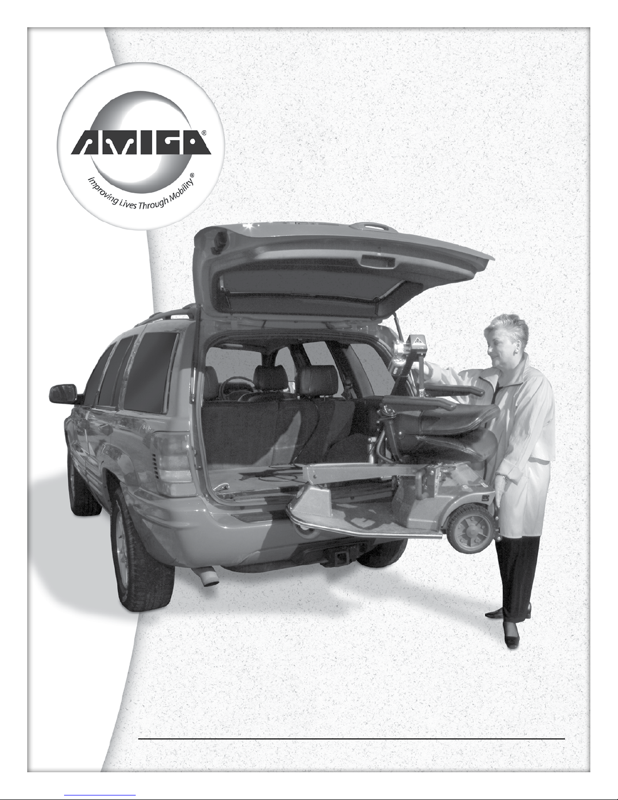
Adjust this second spacer over the estimated center of the weight of the vehicle and tighten securely (#2, Figure 7a). Next,
®
boom to the operating position, and swing out over the rear trunk opening. (Refer to section “Operating
®
”, on page 9.)
Lower the boom S-hook and attach it to the lift arm assembly (#2, Figure 7a). Raise your POV o the ground 2-3
inches (5.08 - 7.62 cm) and observe whether it is level. If not, lower the POV and relocate the second spacer along the
adjustment slot until the POV is level.
LIFT BRACKET INSTALLATION OPTIONAL
The optional lift bracket can be used in vans or SUVs to lift the entire POV without
removing the seat and/or
handle. It is installed in place of the standard S-hook.
To attach the lift bracket to the lift webbing, remove the button head screw and one retaining collar from the tube.
Place the tube through the loop in the webbing directly over the J-hook on the other end of the lift bracket.
Reinstall the set collar and the button head screw and tighten the screws securely.
operAting Your Lift•ALL®
Upon raising your lift strap, make sure that the top of the S-hook does not go past the bottom of the strap enclosure. Keep
strap twisting to a minimum. Before lifting your mobility aid, make sure the end of the S-hook is completely engaged around
adjustment spacer. (Figure 7a, No. 2 adjustment spacer.)
STEPS TO LOADING POV INTO TRUNK
1)
Unhook the shock cord from the end of the boom. Lift the boom until you can latch the S-hook over the 1/2-inch
(1.27 cm) diameter bolt at the boom inner end using the black handle (Figure 8).
2)
Park your POV close to the car, parallel to the rear bumper. Remove the seat from the POV. Remove or fold down the drive
handle of the POV.
www.myamigo.com 9

3) Swing the boom out until the boom outer end is over the lift arm attached to your seat post. Push DOWN on
the electrical switch located at the boom outer end to lower the
S-hook. Attach the S-hook to the adjustment spacer (Figure 7a,
No. 2) on the lift arm. Make sure the lift strap webbing is straight
and not twisted (Figure 9).
4)
Press UP on the electrical switch until your POV wheels clear the
top edge of the trunk opening. Steady the POV with your hand as it is
lifted.
While lifting your POV, make certain that your hands are clear of
the S-hook. Make sure the top of the S-hook does not go past the
bottom of the strap enclosure and that the S-hook is completely
engaged in the bar.
5) Slowly swing the boom toward the side of the trunk and turn
the suspended POV so it will clear the sides of the trunk.
6) Press DOWN on the electrical switch and slowly lower
your POV onto the oor of the trunk guiding it with your
other hand (Figure 10).
7)
Remove the S-hook from the lift arm on your POV’s seat post.
Lift up the outer end of the boom and unlatch the S-hook from
the boom inner end.
8) Lower the boom to a horizontal position and reattach the
shock cord hook.
9) Place the seat and other components of your POV in the
trunk and carefully close the lid.
TO UNLOAD YOUR POV, REVERSE ABOVE PROCEDURES.
10 www.myamigo.com

TROUBLESHOOTING/
SERVICE QUESTIONS
Question? The lift hook goes up when I press the switch to the down position.
POSSIBLE SOLUTION: The lifting strap (#3077) is wound backwards around the spool assembly (#980008). To correct
this, press the switch in the UP position and hold it there until the strap completely winds up again.
Question? My Lift•All
®
works ne without my POV attached,
but when I try to lift it, it lifts slowly or not all the way to the top.
Possible Solutions:
1) Make sure that the black ground wire from the boom is grounded properly to the L-bracket.
2) Try lifting your POV with the car engine running. Your car battery may be weak.
3) Clean and tighten the booster bolt connection to the car battery and the red power wire.
Question? My Lift•All®will not work at all.
Possible Solutions:
1) Check fuse in red power wire assembly running from car battery. Replace fuse if it has blown. An extra fuse has
been provided with the unit.
2) Reset the circuit breaker (#5595).
3) Check lift for loose wire connections.
4) Check lift motor and replace it if not functioning.
Question? My lift works, but it stops intermittently.
Possible Solutions:
Check for loose wire connections.
Question? My lift works in only one direction.
Possible Solutions:
1) Check for loose wire connections to the switch (#341035).
2) Replace defective switch.
Question? The rear of my POV hangs lower than the front when being lifted. How can I make it level?
Possible Solutions:
Loosen adjustment spacer, then lift your POV 2-3 inches (5.08 - 7.62 cm)
o ground and slide spacer until vehicle is level. Make sure the spacer is then tightened securely.
If these suggestions do not solve the problem, please call our Service Hotline: 1-800-248-9131
or your local Amigo representative.
www.myamigo.com 11

MAINTENANCE RECOMMENDED
for Your Lift•ALL®
®. Take a moment to review these suggestions and
keep them handy for future reference.
EVERY THREE MONTHS
BRACKET MOUNTING BOLTS: Retighten the bracket mounting bolts after the rst 90 days of use.
GEAR MOTOR ASSEMBLY: Check the lift strap retainer screw and tighten as required.
LIFT STRAP: Check the lift strap for unusual wear and replace if needed.
POWER WIRE ASSEMBLY: Check the connections at the battery, fuse, and other connections under the hood for
corrosion. Clean and coat with a light layer of grease as needed.
EVERY SIX MONTHS
FASTENERS: Check all nuts, bolts, and screws every six months to make sure they are tight.
12 www.myamigo.com

www.myamigo.com 13
LIFT-All® WARRANTY
3-Year Limited Warranty – Effective July 9, 2003
Amigo Mobility International, Inc. (AMI) warranties the original completed product
it manufacturers to the original purchaser.
1. Structural components have a 3-year limited warranty against defects in materials and workmanship.
2. Motor and gear assembly are warranted against defects in materials and workmanship for two (2) years.
3. Weight Restrictions: Use of this product with a load in excess of 200 lbs. (90 kg)
is not recommended and voids warranty.
4. After sixty (60) days, labor will be charged on warranty repairs, except where law prohibits.
5. Items replaced under warranty, are covered by the original warranty.
(Warranty replacement does not extend the warranty period.)
6. AMI is obligated to repair or replace products or parts returned by the purchaser, and found to be
defective under warranty at its headquarters in Bridgeport, Michigan.
7. For unit and parts, this warranty does not cover accidental damage, misuse, normal wear and tear,
such as electrical and mechanical switches, wires, belts, chains and resistors, or use of products for
other than personal purposes. Damage during shipment is not covered by the warranty.
8. If inspection determines that a returned part or unit is fully functional, it will be returned
at the expense of the owner. Opening sealed components will void the warranty.
9. Accessories and parts that are not a part of the original completed unit, or rebuilt units,
will have a one (1) year warranty against defects in materials and workmanship.
This warranty begins when the unit is sold to the original owner. If warranty information,
such as owner’s name, serial number or date of purchase is not available, then AMI will use
the production date of the unit as the effective warranty date.
This warranty supersedes and is in lieu of all other warranties, expressed or implied, and no person,
agent or dealer is authorized to give any warranties on behalf of AMI, nor to assume for AMI any
other liability concerning any of its products unless made in writing and signed by an official of AMI.
Any unauthorized repair or modification will void this warranty and release AMI from any liability.
This warranty gives you specific rights, with the possibility of other rights,
which vary depending upon your locality.

14 www.myamigo.com
WIRING DIAGRAMS

www.myamigo.com 15
EXPLODED VIEWS
(Lifting POV with seat

16 www.myamigo.com
EXPLODED VIEWS

www.myamigo.com 17

18 www.myamigo.com
(Lifting POV with seat

www.myamigo.com 19

PARTS LISTS
20 www.myamigo.com
Upper Boom & Motor Assembly
Part Number Description Quantity
1055 Bearing 1.37 OD, 0.625 ID with Ring 1
1167 Nut, 1/4-20 Hex Keps 2
1215 Washer, Spring Lock, #10 2
1291 Grommet 1
1391 Screw, Button Head Cap, 1/4-20 x 0.50 LG 2
1479 Screw, Round Head, #10-32 x 0.625 LG 2
1480 Nut, Hex Acorn, #10-32 2
1567 Switch, Extention 1
2256 Switch, Shield 1
2296 Nut, Hex Jam, 15/32-32 1
2404 Screw, Flat Head, #10-32 x 0.5 LG 1
2433 Screw, Phillips Round Head, #8-32 x 1.25 LG 4
3019 Switch Guard Cover 2
3077 Lift Strap 1
3690 Label, Patent 1
4179 Washer, Lock, 0.05 ID 1
5190 Screw Cap, 1/4-28 x 0.75 LG 3
5578 Spacer, #8-32 x 0.38 OD 0.50 LG 4
5580 Lift All Boom 1
5586 Bearing Plate 1
5587 Switch Bracket 1
5616 Screw, Self Tapping, 1/4-20 x 0.62 LG 3
5620 Label Lift All Logo 1
5627 Label, Warning 1
5668 Retainer 1
6853 Spool 1
8746 Hook Stop 1
341035 Switch 1
980008 Spool Assembly 1
Bracket for Van Installation
Part Number Description Quantity
1025 Bearing, 1-3/16 OD, 1-1/16 ID 1
1081 Bearing, 1.185 OD, 1.067 ID 1
1189 Washer, Cone Lock, 0.38 ID, 0.75 OD 3
1253 Nut, Hex Keps, 5/16-18 1
1275 Nut, Hex 5/16-18 3
2448 Pin, Roll, 1/8 x 0.5 LG 1
5548 Collar Clamp, 1-1/16 Bore 1
5567 Screw, Hex, 5/16-18 x 2.0 LG 1
5595 Circuit Breaker, Manual Reset, 15A 1
5654 Support Weldment, Left Hand 1
5660 Lift All Connector Weldment 1
6161 Support Weldment, Right Hand 1
6765 Circuit Breaker Bracket 1
8939 Screw, Hex, 5/16-18 x 4.0 LG 3
11237 Washer, 6 Sided 3
Table of contents
Popular Lifting System manuals by other brands

Ingersoll-Rand
Ingersoll-Rand BHD15 instruction manual

vimec
vimec V59 Programming handbook

stellar labs
stellar labs 108-12 Flex owner's manual

ShoreStation
ShoreStation SSV1564M Assembly guide

REID LIFTING
REID LIFTING PORTADAVIT QUANTUM PDQ 1 Assembly & Operation guide

Athena
Athena 850-BL EVO TRANSLATION OF ORIGINAL INSTRUCTIONS