Amiko MultiTracker 3 User manual

AMIKO MultiTracker 3
User's Manual
www.amikostb.com
1. INTERFACE, BUTTONS AND INDICATORS.................................................................................2
1.1 INTERFACE:..................................................................................................................2
1.2 BUTTONS AND INDICATORS..........................................................................................2
2. BASIC FUNCTIONS.................................................................................................................3
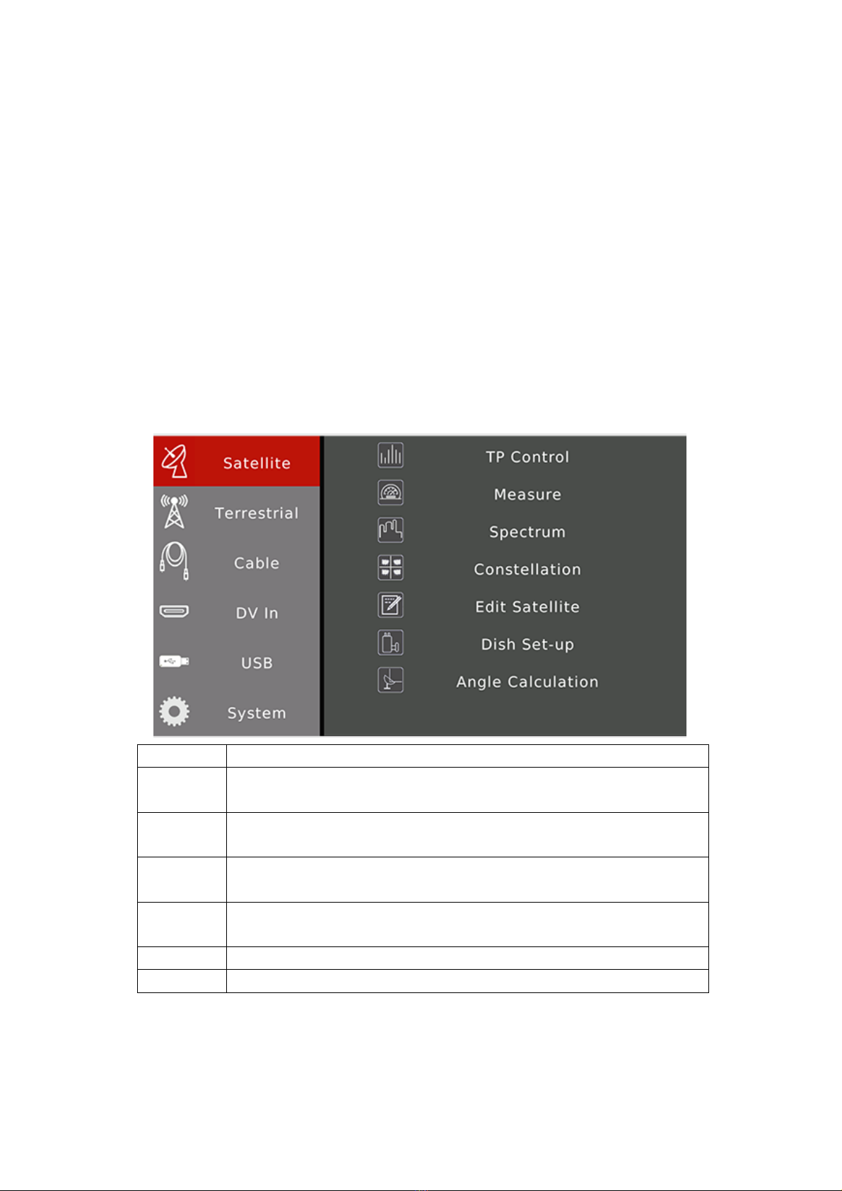
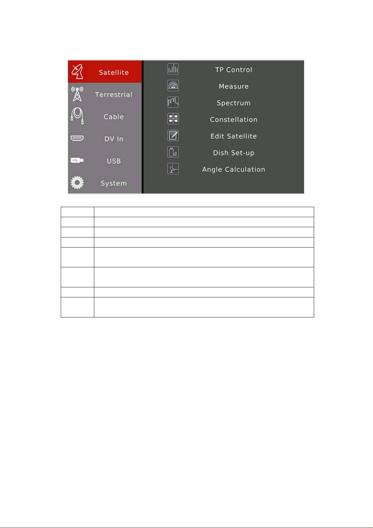
2.1 Satellite.......................................................................................................................4
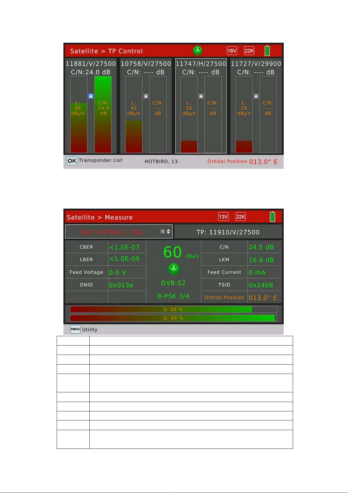
2.1.1 Satellite > TP Control .........................................................................................4
2.1.2 Satellite >Measure.............................................................................................5
2.1.3 Spectrum Analyzer.............................................................................................6
2.1.4 Satellite > Constellation .....................................................................................7
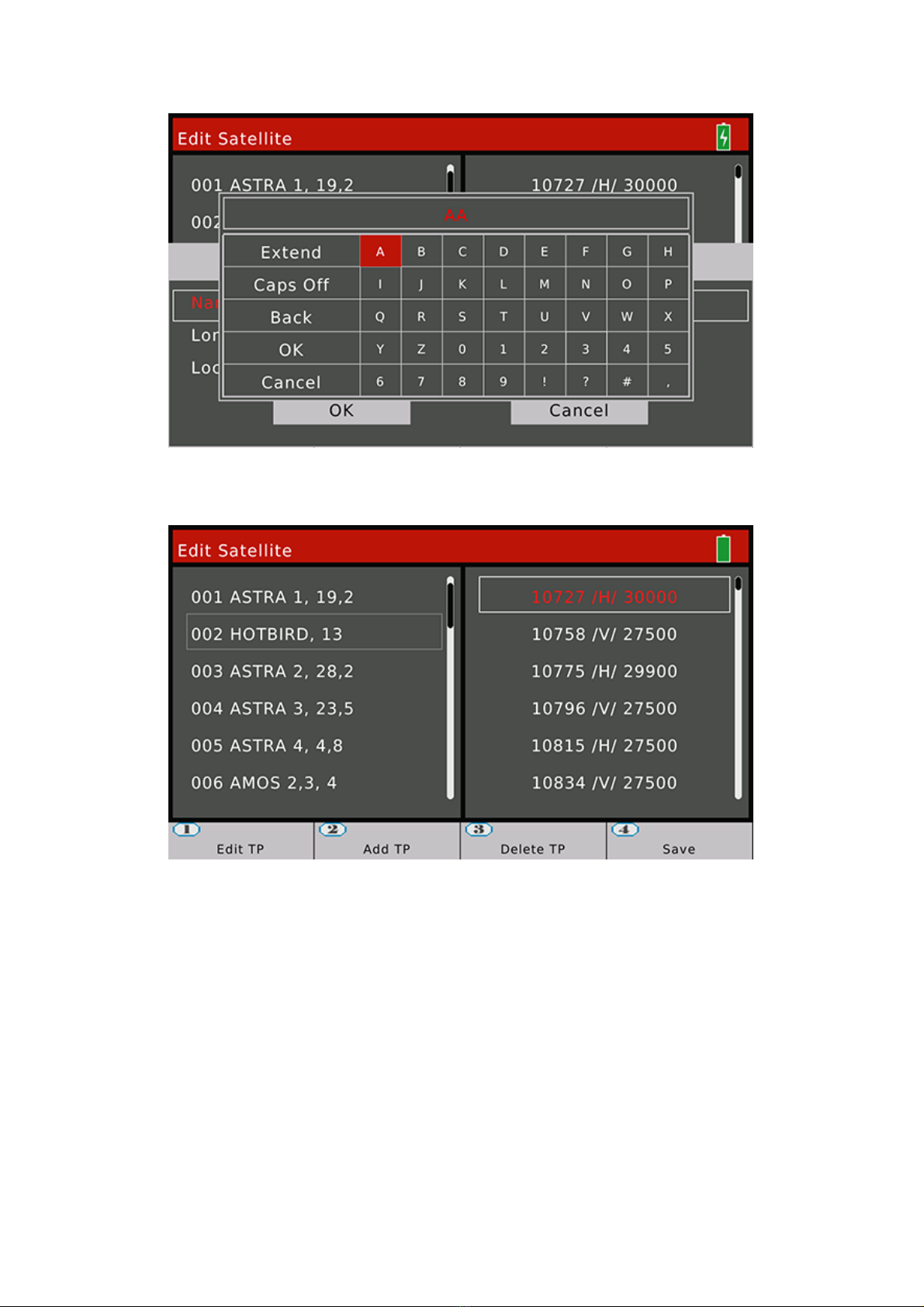
2.1.5 Satellite > Edit Satellite ......................................................................................7
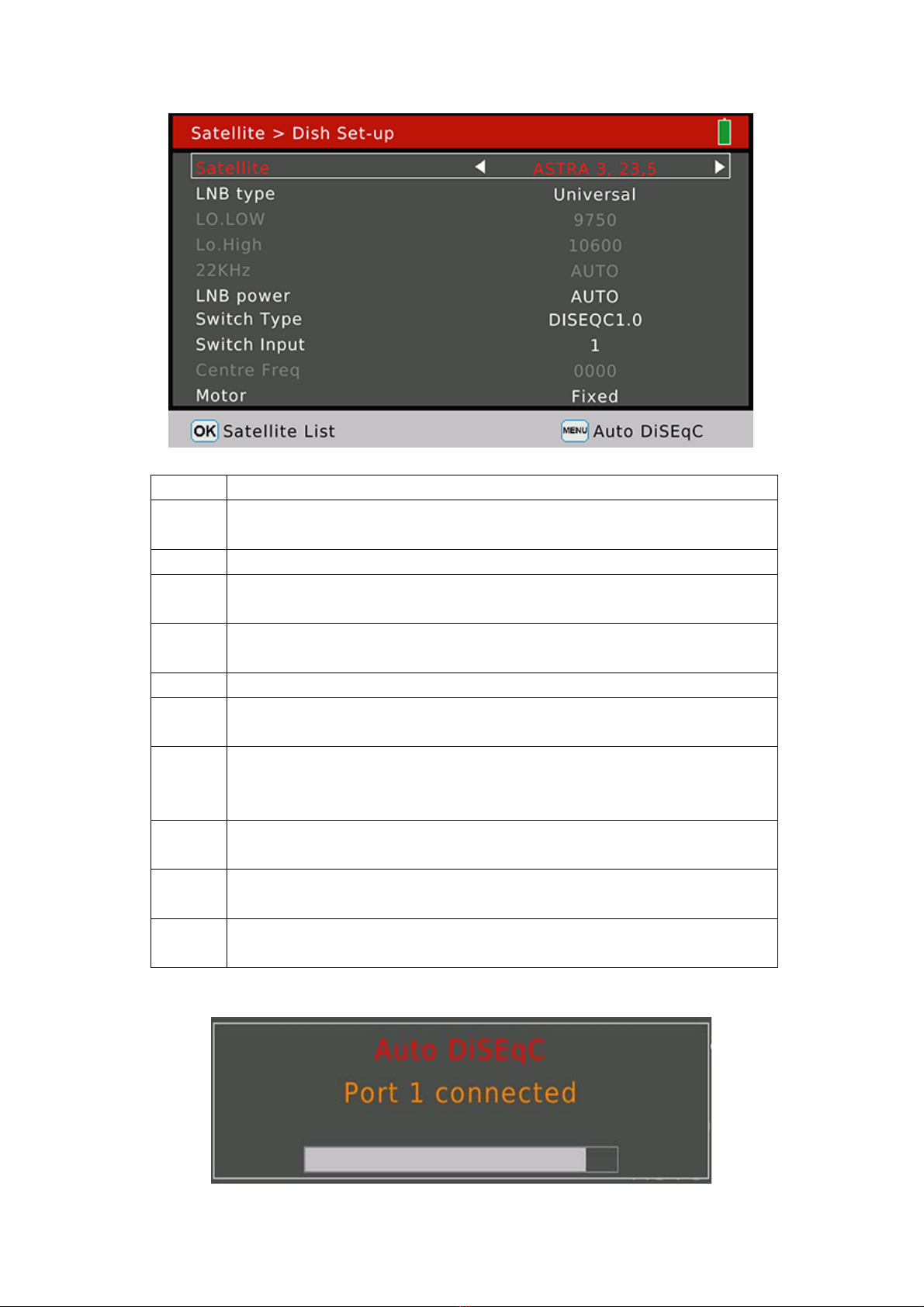
2.1.6 Satellite > Dish Set-up........................................................................................9
2.1.7 Satellite > Angle Calculation.............................................................................12
2.2Terrestrial...................................................................................................................14
2.2.1Terrestrial > Scope............................................................................................15
2.2.2 Terrestrial>Measure.........................................................................................15
2.2.3Terrestrial > Spectrum ......................................................................................16
2.2.5 Terrestrial>Channel Edit...................................................................................18
2.2.6Terrestrial > Edit Emetteur ................................................................................18
2.3 Cable.........................................................................................................................19
2.3.1Cable > TILT......................................................................................................20
2.3.2 Cable>Measure ...............................................................................................20
2.3.3 Cable>Spectrum..............................................................................................21
2.3.4 Cable>Constellation.........................................................................................21
2.3.5 Cable>Channel Edit..........................................................................................21
2.4 DV IN ........................................................................................................................21
2.5 USB...........................................................................................................................22
2.6 System ......................................................................................................................22
2.7. Play Program Menu ..................................................................................................23
2.8 Screenshot ................................................................................................................24
2.9 Debug information.....................................................................................................25
1

1. INTERFACE, BUTTONS AND INDICATORS
1.1 INTERFACE:
DC 12V IN: The DC power supply in jack of meter. Please check the output voltage of adapter
carefully before plug-in. The meter would be damaged if the input voltage is higher
than 12V.
USB: The USB port for USB device to plug-in.
DV IN: The digital video input port.
RESET: The reset button of the meter.
AV OUT: The analog video and audio output port.
RF IN: The antenna or LNB RF signal input port. RF type, female.
1.2 BUTTONS AND INDICATORS
0-1
SCREEN: The screen for display for meter
Indicators:
POWER: The red LED will be on if the meter is working
RF POWER:The yellow LED will be on if the power supply of LNB/antenna is on
LOCK: The green LED will be on if the connected signal locks
CHARGE: The LED will be RED if the meter is in-charging. And it will be green if the battery if full
Buttons:
POWER: Press and hold on about 3 second to turn on or turn off the meter
2

MENU: Enter or exit menu
EXIT: Exit current menu or current operation
0~9 NUMBER KEYS: Input numeric values. Please refer to help bar of each menu for other functions
▲/▼: Zapping channels or navigation in the menu
◄/►: Decrease or increase the volume or navigation in the menu
OK: Enter channel list menu in video playing screen; in other menu, press to confirm your selection
or operation
2. BASIC FUNCTIONS
Turn on the power switch and then the device will enter to Main Menu. Press [EXIT] to enter video playing menu.
Press OK to enter submenu to analyzer or set parameters. Press [///] to navigation.
Items Instructions
Satellite Functions for satellite. Press [OK]/ to enter right function items. Press [EXIT]/ to exit
back to left.
Terrestrial Functions for terrestrial. Press [OK]/ to enter right function items. Press [EXIT]/ to
exit back to left.
Cable Functions for cable. Press [OK]/ to enter right function items. Press [EXIT]/ to exit
back to left.
DV In DV input function. Press [OK] to enable digital video input by DV IN port. Press [EXIT] to
back.
USB USB for software updating
System The meter system settings
3

2.1 Satellite
The functions for satellite digital signal. Press [/] to navigation. Press [OK] to enter sub-menu.
Items Instructions
TP Control Show 4 transponders signal status on one screen.
Measure Show many testing results of input signal. Such as strength, quality, CNR, BER...
Spectrum Show the spectrum chart of input satellite signal
Constellati
on
Show the constellation chart of input satellite signal
Edit
Satellite
Edit the saved satellites parameters, such as edit, add and delete
Dish Set-up Set dish parameters for satellites. Such as LNB type, DiSEqC, motor type...
Angle
Calculation
Calculate the antenna elevation and azimuth according to the local position. And also the
meter can simulate aligning progress of antenna.
2.1.1 Satellite > TP Control
The menu show 4 transponders testing results on one screen. And also show the satellite orbital
position from real signal if it is available in the in transponder stream. The face icon set to smile
one if the real orbit in the transponder stream is same to the current selected satellite in the
meter.
Press to pop-up transponders list to change the current transponder
4

2.1.2 Satellite >Measure
The menu shows many testing results of input signal. Press [/] to switch items and press [/] to change
curser focus between satellite and transponder.
Items Instructions
13V The LNB power supply status of LNB. The values are 13V, 18V and off
22K The 22K status of LNB. The values are 22K and off
SAT: Show and choose the satellite. Press [/] to change, or press [OK] to enter satellite list
TP: Show and choose the transponder. Press [/] to change
, or press [OK] to enter
transponder list. Press numeric button to enter edit pop-up window.
CBER The testing result of CBER
C/N The C/N ratio of signal
LBER The testing result of LBER
LKM The testing result of LKM
Feed
Voltage
The feed voltage of LNB
5

Feed
Current
The feed current of LNB
ONID The original network identification from transponder stream
TSID The transponder stream identification from transponder stream
60 dBμV The power level of input signal of current transponder
Face Icon It sets to green smile one if the signal is locked, or set to red sad one
DVB-S2 The satellite system of input signal
8-PSK 3/4 The demodulation mode and FEC value of input signal
Orbit
Position
The satellite orbit value from transponder stream
S: The signal strength in percent
Q: The signal quality in percent
Press [MENU] to pop-up window to search channels on single transponder or all transponders mode. Press [OK]
to enter channel search menu. The meter will enter to channel play menu if the search progress is finished.
2.1.3 Spectrum Analyzer
The menu display the spectrum chart of input signal.
Instructions
Button 1 Press [1] to set the frequency range to 200MHz around current set frequency
Button 2 Press [2] to set the frequency range to 400MHz around current set frequency
Button 3 Press [3] to set the frequency range to 800MHz around current set frequency
Button 4 Press [4] to set the frequency range to 1200MHz around current set frequency
Button 5 Press [5] to switch between Analyze and Pause status
Button 7 Press [7] to switch between LO Low and LO High if the LNB type is double values
Button 8 Switch LNB voltage output between 13V and 18V
Press [OK] to check the current frequency is be locked or not on blind mode. The real frequency , symbolrate and
also the satellite orbit if the value is available in the transponder stream.
6

2.1.4 Satellite > Constellation
The menu shows the constellation chart of input signal if the current transponder is locked. And also the C/N ratio,
power level, CBER, DVB system and demodulation mode.
Press [///] to change current transponder. Press [OK] to pop-up transponders list to help to select
easily.
2.1.5 Satellite > Edit Satellite
The menu can edit, add and delete satellites and also transponders of satellite. Press [/] to
focus satellites list or transponders list of selected satellite.
Edit satellites (when satellite item is selected)
Instructions
[OK]/[1] Press to show edit dialog to edit satellite name, orbit and position
[2] Press this button to add new satellite
Step1: Set the satellite name, longitude and location
Step2: Set the antenna parameters for the satellite
[3] Press this button to delete current selected satellite. A dialog will display on screen, user
7

can confirm or cancel the delete operation
[4] Press this button to save all the modifications
Edit Satellite
Delete satellite confirm dialog
8

Edit satellite name dialog
Edit transponder (when transponder list is selected)
User can edit, add and delete transponder in this menu.
2.1.6 Satellite > Dish Set-up
All the parameters of dish will be set on this menu. Such as LNB type, LNB power, motor type...
9

Press [///] to navigation.
Instructions
Satellite Show and choose satellites. Press [/] to select satellite, or press [OK] to enter Satellite
list.
LNB Type Set LNB Type, press [/] button to switch between values. Default set to UNIVERSAL
LO.LOW Show the low local oscillator value. Use digital button to input the LO.LOW once the LNB Type
is customized
LO.HIGH Show the low local oscillator value. Use digital button to input the LO.HIGH once the LNB Type
is customized
22KHz Set 22K status. Press [/] button to switch between ON/OFF/Auto. Default set to Auto
LNB
Power
Set the antenna power. Press [/] button to switch between Auto/13V/18V/OFF. Default
set to Auto
Switch
Type
Set DiSEqC type. Press [/] button to switch between None/DiSEqC1.0/
DiSEqC1.1/SCR_PORT_A/SCR_PORT_B/SCD2_PORT_A/SCD2_PORT_B/SCD2_PORT_C/SCD2_P
ORT_D. Default set to None
Switch
Input
Set DiSEqC1.0 or DiSEqC1.1’s input port. Or set user band for SCR and SCD2. Default set to
None
Centre
Freq
Set user band frequency for SCR and SCD2
Motor Set antenna motor type. Press [/] button to switch between Fixed / DiSEqC1.2/USALS.
Default set to Fixed
Press [MENU] button to enter auto DiSEqC function dialog. The meter will find out the connected port of DiSEqC
1.0 automatically. The switch type willset to DiSEqC 1.0 if the connected port is found.
10

DiSEqC1.2:
On this menu, user can set the antenna to right position by DiSEqC 1.2 command if the antenna supported DiSEqC
1.2 function.
According to the signal strength and quality in percent, the meter can get the best signal by sending command to
adjust antenna to right position.
.
Instructions
Satellite Show the current selected satellite.
Transponde
r
Show and choose the current transponder of the satellite. Press [/] to switch between
transponders.
Move Press [/] to send command to move antenna to East or West by step mode. Press [/]
and hold on to send command to move antenna to East or West by continual mode. Press
[EXIT] to send pause command to exit moving progress.
Centre
position
Press [OK] to send command to move antenna to centre position
Set limit Press [/] button to send command to set limitation to move to East or West
Save Press [OK] to send saving command to save current antenna position for satellite
USALS:
On this menu, user can set the antenna to right position by USALS command if the antenna supported USALS
function.
User can select the local city in the saved cities list. The local longitude and latitude will be set as saved in the
meter once the city sets. Or user can press [OK] to edit the local longitude and latitude manually if the city sets to
customized.
Press [1] to send command to move antenna to the right position.
Press [2] to send command to move antenna to centre position.
11

Instructions
HOTBIRD,13 Show the current selected satellite.
Ankara The default cities list. The local longitude and latitude will be set once the city is selected.
Move Press [/] to send command to move antenna to East or West by step mode. Press [/]
and hold on to send command to move antenna to East or West by continual mode. Press
[EXIT] to send pause command to exit moving progress.
Edit local longitude and latitude
2.1.7 Satellite > Angle Calculation
The menu calculates the right azimuth and elevation of antenna according to the satellite orbit and testing local
longitude and latitude.
12

Instructions
HOTBIRD,13 The current selected satellite. Press [/] to switch satellites. Press [OK] to enter the
satellite list to select
Ankara The default cities list. The local longitude and latitude will be set once the city is selected.
Or user can press [OK] to edit the local longitude and latitude manually if the city sets to
customized.
39.4 The elevation of antenna to align to the current satellite
209.4 The azimuth of antenna to align to the current satellite
-22.1 The polarization of antenna
Press [2] to enter compass menu. The menu try to simulate the align progress of antenna to find out the best
elevation and azimuth by moving the direction and angle of meter.
Press [3] to enter align menu. The menu try to lead user to find out the right elevation and
azimuth of antenna by moving the direction and angle of meter.
13

2.2Terrestrial
This menu for DVB-T/T2 functions. Please see below screenshot
Press [/] to navigation and press [OK] to enter into sub-menus.
Instructions
Scope The menu shows four channels` signal testing results on one screen
Measure The menu shows many testing results for selected channel
Spectrum The menu shows spectrum chart of input signal
Constellation The menu shows constellation chart of selected channel once it is locked
Channel Edit
User can edit channel`s parameter on this menu, such as frequency, system type and
bandwidth
Edit
Emetteur
Select correct channels that can available of testing field on this menu.
14

2.2.1Terrestrial > Scope
The menu shows four channels` signal testing results on one screen. The meter will check channels one by one
automatically.
Press [OK] to pop-up channels list to help to select channel to replace the current focused one.
Press [MENU] to pop-up emittor list to help to switch emittors easily.
2.2.2 Terrestrial>Measure
The menu shows many testing results for selected channel. Please see below screenshot for detail.
Instructions
Emetteur5 The testing field name. Press [/] to switch values and press [OK] to pop-up list to
help to select easily.
CH: The channel name Press [/] to switch values and press [OK] to pop-up list to help
to select easily.
490.00 MHz The frequency of channel
DVB-T 8 MHz The terrestrial system and bandwidth. Press [/] to switch values and press [OK] to
15

pop-up list to help to select easily.
CBER The CBER value of input signal
MER The MER value of input signal
LBER/VBER The LBER/VBER value of input signal.
Pilot Pattern The pilot pattern value of input signal
Feed Voltage The feed voltage value of antenna
Feed Current The feed current value of antenna
Cell ID The cell ID value of input signal
FFT Mode The FFT mode of input signal
ONID The original network identification of input transport stream
TSID The transport stream identification
Guard Interval The guard interval value of input signal
NIT Version The version value of network identification table
82 dBuV The power level of input signal
DVB-T2 The digital system of terrestrial of input signal
16-QAM 5/6 The modulation and FEC value of input signal
S: The strength of signal in percent
Q: The quality of signal in percent
Press [MENU] to pop-up window to help to search channels or set power supply to antenna.
2.2.3Terrestrial > Spectrum
The menu shows spectrum chart of input signal
16

Instructions
Centre
Freq
The current frequency to show power level value
118
dBuV
The power level value of current frequency
Channel
No.
The name of channel which frequency is close to current frequecny.
Button 1 Press [1] to set the frequency range to 200MHz around current set frequency
Button 2 Press [2] to set the frequency range to 400MHz around current set frequency
Button 3 Press [3] to set the frequency range to 600MHz around current set frequency
Button 4 Press [4] to set the frequency range to 800MHz around current set frequency
Button 5 Press [5] to switch between Analyze and Pause status
/To set the power level range of spectrum chart
/To set the current frequency
17

2.2.4 Terrestrial > Constellation
Please refer to 2.1.4.
2.2.5 Terrestrial>Channel Edit
User can edit channel parameters on this menu. All the channels for terrestrial will be listed on this menu. Press
[/] to switch channels.
Press [OK] to enter the edit mode. And then press [/] to switch between frequency, type and bandwidth
2.2.6Terrestrial > Edit Emetteur
Choose the available channels for each Emetteur on this menu. Press [/] or [/] to navigation and press
[MENU] to edit the name of current emetteur.
All the channels list on the right screen. The channels with red rectangle belong to current selected emetteur. Press
18

[OK] to add or delete from the emetteur.
2.3 Cable
This menu for digital cable functions.
Items Instructions
TILT The menu shows four channels signal testing results on one screen
Measure The menu shows many testing results of channels
Spectrum The menu shows spectrum chart for cable signal
Constellation The menu shows constellation chart for digital cable signal
Channel Edit User can edit channel parameters on this menu. Such as frequency, digital cable system
and symbol rate
19

2.3.1Cable > TILT
The menu shows four channels` signal testing results on one screen. The meter will check channels one by one
automatically.
Press [OK] to pop-up channels list to help to select channel to replace the current focused one.
2.3.2 Cable>Measure
The menu shows testing results for digital cable signal. And also can search programs once the
signal is locked.
Instructions
CH: The channel name Press [/] to switch values and press [OK] to pop-up list to help
to select easily.
FRE: The frequency of channel
SYM: The symbol rate of channel
CBER The CBER value of input signal
20
Table of contents