Amoonsky Technology AMS-SC358 User manual

1
LED Video Splicer &Processor
AMS-SC358
User Manual
LED Video Processor
户手册
User’s Manual

2
Safety Instructions
This symbol prompts the user, the device user manual has important operating and
maintenance instructions.
This symbol warns the user of the equipment inside the enclosure exposed to
hazardous voltages, there is the risk of electric shock.
Note
Read the manual• Read and understand all safety and operating instructions before using the
equipment.
Save the manual• The safety instructions should be kept for future reference.
Follow Warnings • Follow all warnings and instructions marked on the equipment or in the user
information.
Avoid Attachments • Do not use tools or attachments that are not recommended by the
equipment manufacturer because they may be hazardous.
Warning
Power sources • This equipment should be operated only from the power source indicated on the
product.
This equipment is intended to be used with a main power system with a grounded (neutral) conductor.
The third (grounding) pin is a safety feature, do not attempt to bypass or disable it.
Power disconnection • To remove power from the equipment safely, remove all power cords from
the rear of the equipment, or the desktop power module (if detachable), or from the power source
receptacle (wall plug).
Power cord protection • Power cords should be routed so that they are not likely to be stepped on or
pinched by items placed upon or against them.
Servicing • Refer all servicing to qualified service personnel. There are no user-serviceable parts
inside. To prevent the risk of shock, do not attempt to service this equipment yourself because
opening or removing covers may expose you to dangerous voltage or other hazards.
Slots and openings • If the equipment has slots or holes in the enclosure, these are provided to
prevent overheating of sensitive components inside. These openings must never be blocked by other
objects.
Copyright
Copyright © 2016 Amoonsky The splicing processor and the video processor manufacturers all rights
reserved.

3
Trademarks
VGA and XGA are registered trademarks of IBM Corporation.
VESA is a trademark of the Video Electronics Standards Association.
HDMI logo and High-Definition Multimedia Interface (High-Definition Multimedia Digital Interface) are
HDMI Licensing LLC. Trademarks.

4
Introduction
This manual contains information about how to use, install and configuration the LED video splicer &
processor, in addition, also relates to knowledge LED video processor and LED video systems. If Use
the LED video processor , please read this manual carefully.
About LED Video Splicing Processor
The LED splicing processor has three powerful video processing cores, multi-graphics multi-input
smart splicing processor, which can be widely used in performing arts activities, command and control
center, video conferencing, hotels, courts and conference rooms.
The LED splicing processor has 3-channel output, 2-channel for splicing, 1 channel for monitoring.
Can achieve 2 × 1 or 1 × 2 channel hybrid splicing, a single product can splice 5.3 million pixel
user-defined output.
The LED splicing processor can accommodate a wide range of input sources, can access up to 11
video inputs, including 2 DVI, 2 HDMI, 4 VIDEO, 2 VGA and 1 SDI (optional). Each channel can
accept standard resolution or high resolution video signals, the DVI and VGA can receive up to 1920
× 1200 @ 60Hz resolution input, to meet a variety of high-definition output.
The splicing processor is easy to use, using the key panel and menu system to complete the complex
settings. A variety of input interfaces, to meet the different signal needs. Built-in 4 LED sending card
installation location to meet the installation requirements of large-screen system.

5
Panel
Rear panel
Video input connector :
● AV1, AV2, AV3, AV4 -- Composite video input, BNC connector, support PAL、PAL-M/N、
NTSC、SECAM.
●DVI1, DVI2 – DVI video input. DVI-I/DVI-D connector. support VESA standard video format.
●HDMI1, HDMI2 – HDMI video input. HDMI-A connector. support HDMI1.3 / VESA standard.
●VGA1, VGA2 – VGA video input. DB-25 connector. support VESA standard video format.
●SDI, SDI-LOOP – SDI video input, loop out. BNC connector.
Video output connector:
● CH-A/CH-B -- DVI video output. DVI-I connector. CH-A, CH-B output same signal.
● CH-M/Monitor -- DVI video output. DVI-I connector. Connect to monitor screen.
RS-232 — Serial communication connector for engineering testing, program burning.
LED sending card slot — Built-in 4 sending card slot.
AC connector — Use IEC standard power cable,input 100-240 VAC, 50-60Hz.
AC switcher — power on/off.
Control connector — Net cable, USB input control.
Audio connector — Audio output (L1 R1 GND L2 R2) .

6
Front panel
LCD display — display the parameters and user settings.
Operating button — operate the menu system.
●OK “confirm”
●ESC “exit” or “back”
●Knob press down “OK”, turn right ”+” turn left ”-” adjust the parameters on menu.
INPUTS — including 11 input signal selection, screen testing function, VGA auto correction.
● AV1, AV2, AV3, AV4 -- video input selection button.
● VGA1, VGA2 -- VGA input selection / auto correction button. Keep press VGA1/2 button
one more time could enable the auto correction function.
● DVI1, DVI2, HDMI1, HDMI2 – DVI, HDMI input selection button.
Indicator light function – the button light on when power on.
(1) Slow flicker:the interval is 1 second and keep flicker – no input signal.
(2) Fast flicker:the interval is 0.3 second – decoding the input signal.
(3) Light on:no flicker – input signal working.

7
FUNCTION — including display mode, black output, preset, pip function and switch type.
● PART/FULL – part screen display function, set the parameters in SPLICE menu.
● PIP – enable/disable the PIP function, set the parameters in PIP menu.
● BLACK – output black/freeze screen, select the output in the FUNC menu.
● SDI – SDI input selection button.
● MODE – save or load the user settings.
● TEST – output testing pattern(colorful image, color bar etc.).
Hint:when PIP function is working, PART/ FREEZE/BLACK/FADE are disabled.
●FADE/CUT – select switching type, support seamless and fade-in/fade-out switching.
●OUT – set the output resolution for A, B output-channel and monitor output.

8
Menu System
1. Default menu
LCD will display the input source, output resolution of each channel and other parameters when the
processor startup.
Input:HDMI 1080p Model:Full
Monitor:1024x768/60 Bright:50
Output A:1024x768/60 PIP :CV1
Output B:1024x768/60
2. Main menu
Main menu display the option of every operation, all the functions could be set in the menu, press
“OK” to enable the main menu when the processor is in default menu.
Option
Description
OUTPUT
Set output resolution for each channel
SPLICER
Set splicing parameters and part display, support equal/unequal splicing.
PIP
Set PIP input source, PIP size, PIP position on the screen.
PICTURE
Set the brightness, contrast, etc.
FUNCTION
Set language, user settings save and load
SYSTEM
Set system function, system version, factory reset etc.
Operation: press the “OK” button or Knob could enable the main menu, “ESC” is return button, turn right or
turn left the knob could adjust the parameters.
OUTPUT
SPLICER
PIP
PICTURE
FUNCTION
SYSTEM

9
Configuration
1. Output resolution
The default output resolution of the processor is 1920x1080/60Hz, user need to set the output
resolution according to the display, this is the first setup of using the processor.
Step 1: select a output resolution which large then the display from the menu,
Main menu: “OUTPUT” → “OUTPUT A/B” → “Standard Resolution” → “OK”
Step 2: tune the output resolution
Tune the output resolution according to the actual display resolution: Horizontal Width,
Vertical Height, Horizontal Start, Vertical Start.
The processor also support user-defined output resolution:
Main menu: “OUTPUT” → “OUTPUT A/B” → “User Resolution”
Then set the parameters according to the actual display resolution.
Hints:After the user resets the output resolution, the system will reset all the parameters of
the splice menu to ensure the consistency of the data. The user-adjusted resolution can only
be smaller than the currently selected resolution. The horizontal start value and the vertical
start value can not be adjusted when the resolution of the fine adjustment is equal to the
currently selected resolution.
2. Configure switching effect
The processor support seamless switching and fade-in/fade-out switching, shortcut key is “FADE”.
There are two different ways to configure the switching effect in main menu:
①Configuration by shortcut key “FADE”, press the “FADE” on front panel.
②Setting in the menu, “FUNCTION” →“Seamless” →“FADE/CUT”.

10
When the indicator light on current switching is fade-in/fade-out, light of is seamless switching.
The time of fade-in/fade-out could be set in the menu “FUNCTION” →“Fade Time”→“0.5s ~ 5s”.
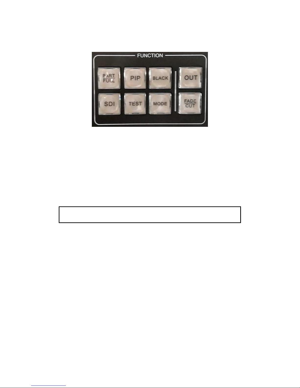
3. Black and Freeze configuration
The processor could output black screen and freeze the screen, this two functions use one button
“BLACK” on the front panel, this shortcut key could be configurated to “black” or “freeze”.
Main menu: “FUNCTION”→“BLACK Function”→“Black/Freeze”
4. User settings save and load
The user settings could be save in the processor to avoid reset when use same operation, the
settings could be loaded from the processor easily. 4 groups are available for the user setting.
(1) Save user settings
This function could save all the parameters which configured by users.
Main menu: “FUNCTION” → “MODE” → “Save Mode” → “Preset[x] ☆” → “OK”
There are 4 groups [0] ~ [3] in the sub menu, when the group is no data, it show ☆, otherwise display
★, The data could be overwrite by users.
(2) Load user settings
There are two different ways to load the user settings, use menu or shortcut key.
①Shortcut key, press the “MODE” button on the front panel when the menu is default, select
a user setting which saved before, press “OK” button or the knob to load.
②Load from menu.
Main menu: “FUNCTION” → “MODE” → “Read Mode” → “Preset[x] ★” → “OK”
5. VGA correction
The processor could correct the VGA input automatically including color, image size and position.
User also could correct the VGA input manually in two different ways.
①Use “AUTO” button on front panel(“AUTO” share the button with VGA1/2), when the
VGA1/2 are selected, press the “VGA1/2/AUTO” again, the processor will correct the VGA.

11
②Use the correction function in menu: select VGA1/2 input enter main menu.
Main menu: “SYSTEM” →“VGA Setting” →“Auto Adjust”
User could set the parameters manually.
Main menu: “SYSTEM” →“VGA Setting” → “H Position”
→ “V Position”
→ “H Clock”
→ “Clock phase”
Hint: When the processor no VGA signal input, the function of correction is disabled, it will
be better to set different output resolution when user VGA1, VGA2 at same time.
6. Language
The processor support two languages Chinese and English, could be changed in menu:
Main menu: “FUNCTION” → “Language/语言” → “ENG/中文”
7. Lock the button
The processor supports button lock to avoid miss operation. Lock in the menu:
Main menu: “FUNCTION” → “Keypad Lock” → “On”
Keep press the “OUT” button 2 seconds to unlock the button.
8. Factory reset
The processor support factory reset if the user parameters are wrong or miss operation, set in menu.
Main menu: “SYSTEM” → “Reset All” → “OK/Cancel”
Warning: factory reset will delete all the user parameters, please be careful to use.
Th

12
e application of splicing
The processor support large splicing output, the maximum output resolution is 7680x640/60Hz or
4608x1152/60Hz, support 5.30 megapixel user-defined resolution output, frame synchronization.
Support bisection splicing, unequal splicing and part display function.
Hints:Before set the splicing parameters,please make sure the output resolution of A and B is
configured.
Enter the “SPLICE” menu and set the parameters as follow:
1. Bisection splicing
①left-right
A B
Sub menu
Output A
Output B
Splice
On
On
Pattern
Equal
Equal
Parameters
Horizontal Units
2
2
Vertical Units
1
1
Position
1
2

13
up-down
A
B
Sub menu
Output A
Output B
Splice
On
On
Pattern
Equal
Equal
Parameters
Horizontal Units
1
1
Vertical Units
2
2
Position
1
2

14
2. Unequal splicing
Sub menu
Output A
Output B
Splice
On
On
Pattern
Unequal
Unequal
Parameters
Horizontal Total
1536
1280
Vertical Total
768
768
Horizontal Start
0
0
Vertical Start
0
0

15
-----Splicing Wizard----
The purpose of this function is to set the parameters quickly and easily.
For example:
Main menu: “SPLICE” →“Splice Wizards” →“OK”
SYSTEM
PIP
OUTPUT
SPLICE
PICTURE
FUNCTION
Splice Wizard >>>
V-Wall-Sync On
Splice A >>>
Splice B >>>
Please set output A size
Horizontal width:1536
Vertical height:768
Please set output B size
Horizontal width:1280
Vertical height:768
Please set the splicing mode
Horizontal splice
A B
OK
Splicing success
OK
OK
OK
OK

16
3. Part/Full display
Part/Full display is based on the splicing function, it could display part of screen for example the
user just need to display the red part as follow. Set the parameters in the menu then use the “PART”
button on the front panel to enable or disable this function.
Full display Part display
Set the parameters of display area, select the input signal for example DVI1 input, enter main menu:
Main menu: “FUNCTION” → “Part Function” → “On”
→ “Part Mode” → “User”
→ “Horizontal Total” → “user defined”
→ “Vertical Total” → “user defined”
→ “Horizontal Start” → “user defined”
→ “Vertical Start” → “user defined”

17
PIP function
1. Picture in Picture
Picture in picture could display two different input source in the same screen. That means in the
normal displaying of the main input, inserted one or more compressed sub-screen in order to monitor
other input. When working in picture-in-picture mode, the user needs to provide at least two signal
input, and make appropriate settings for PIP. This function can also achieve the effect of POP, it is a
special application of PIP.
(1) Enable the PIP: use “PIP” button on the front panel or the menu,
Main menu: “PIP” →“PIP Mode” →“PIP”
Hint:The fade-in/fade-out and seamless switching will be disabled, when PIP is working.
(2) Set the PIP display size and position, PIP frame and transparency in “PIP” menu.
Sub menu
Value
PIP Mode
PIP
Input
User-defined
PIP PARAMS
PIP Horizontal width
User-defined
PIP Vertical height
User-defined
PIP Horizontal start
User-defined
PIP Vertical start
User-defined

18
(3) The PIP function doesn’t work between the same type signal, please check the following table
which show the conflict.
Main Input
A V 1
AV2
AV3
AV4
VGA1
VGA2
DVI1
DVI2
HDMI1
HDMI2
SDI
PIP
AV1
√
×
×
×
√
√
√
√
√
√
√
AV2
×
√
×
×
√
√
√
√
√
√
√
AV3
×
×
√
×
√
√
√
√
√
√
√
AV4
×
×
×
√
√
√
√
√
√
√
√
VGA1
√
√
√
√
√
×
√
√
√
√
√
VGA2
√
√
√
√
×
√
√
√
√
√
√
DVI1
√
√
√
√
√
√
√
×
√
√
√
DVI2
√
√
√
√
√
√
×
√
√
√
√
HDMI1
√
√
√
√
√
√
√
√
√
×
√
HDMI2
√
√
√
√
√
√
√
√
×
√
√
SDI
√
√
√
√
√
√
√
√
√
√
√
2. Keying Color Cutout
This function could cutout the red, green, blue, black and white color from input signal in order to
achieve some simple special effects processing and superimposed subtitles. For example as follow:
PIP input Main input Output effects
Main menu: “PIP” → “PIP Mode” → “Keying”
“PIP” → “PIP Mode” → “Keying Setup” → “Input ” → “DVI1”
“PIP” → “PIP Mode” → “Keying Setup” → “Chroma Key” → “Black”
Table of contents