6
3.SAFETY
3.2 INADVISABLE USE
The machine can not be used for:
•For uses different from those listed in 3.1 paragraph
•In an explosive or aggressive atmosphere, where there is a high density of dust or oily substances suspended in the air
•In a flammable atmosphere
•Outside in all weather’s severity
•With disconnected electromagnetic interblocks
•With electric bridges and/or mechanical instruments leaving out some machine parts or functions
•For working materials not suitable with the machine’s characteristics
Note: it is absolutely forbidden to cut different materials (glass, ceramic. etc..) in particular iron (or similar)
materials.
3.1 SCHEDULED USE
The Machine is designed and built for 45° cuts of wood moulding, hard plastic, and light alloys. When cutting alloys it is
necessary to equip the machine with a Mist Spray Cooling System and the correct blades.
The machine is projected for manual use only (under operator control).
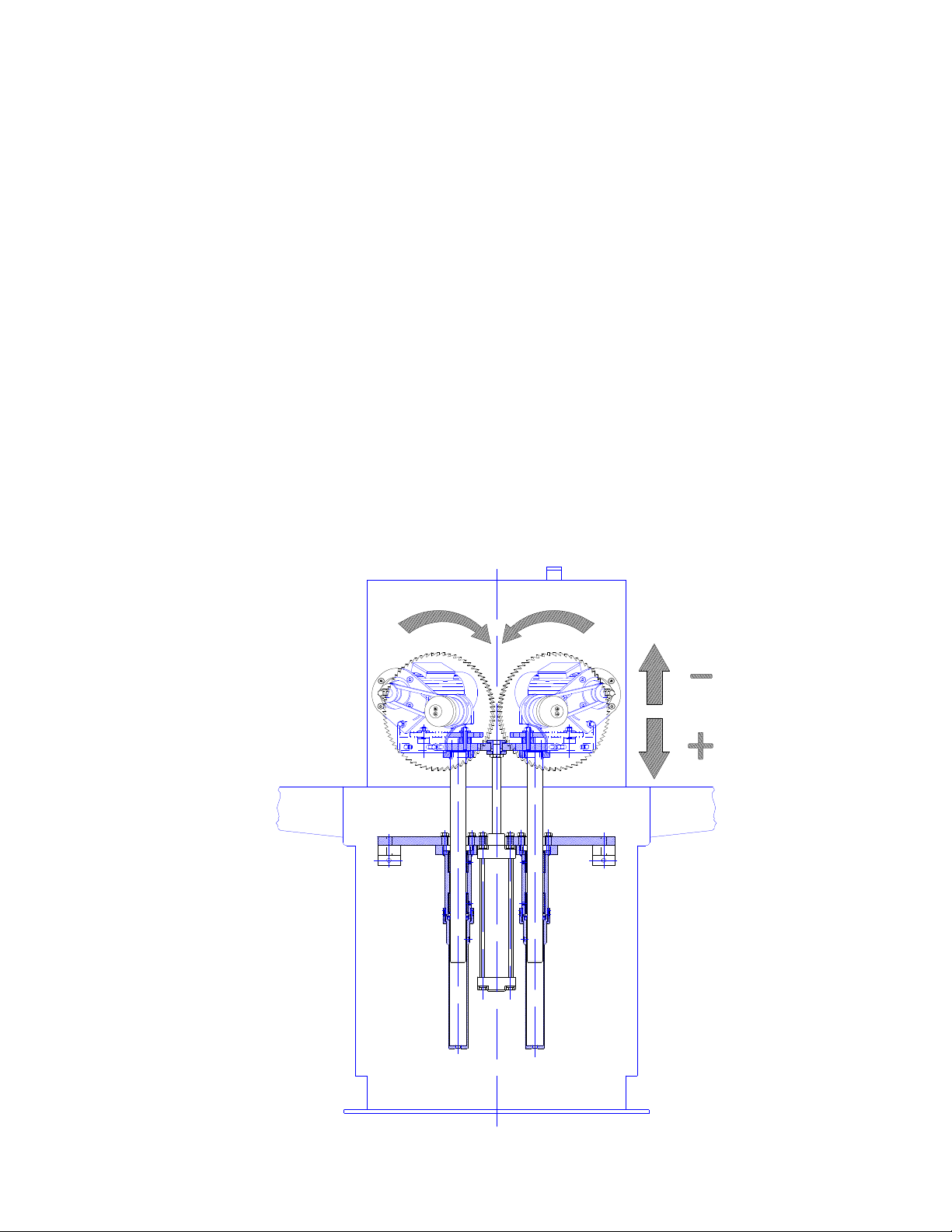
3.3 PROTECTION DEVICES
The machine is equipped with adequate protections for persons exposed to the risks due to the several moving parts (blades,
pulleys, belts, etc....), or movable organs taking part in working (blades) or ejection of wooden pieces, swarfs or dust.
3.5 SAFE WORKING PROCEDURES
The machine is projected and realized to eliminate any risk connected with its use.
Due to the necessity of steering the piece around the blades working area, it is impossible to eliminate the risks related with
possible accidental contact of the operators hands within the work area.
The other risks related with working are:
•Cut (due to hands contact with blades)
•Entanglement (due to wearing loose garments)
•Ejection of worked material splinters
To reduce the consequences of the above mentioned dangers, it is necessary to abide by the following instructions:
1 when the hands are working in the proximity of the blades, you have to steer the piece using a tool
2 avoid cutting moulding pieces smaller than 50 mm in length
3 never use your hands to take out the short pieces and/or cuttings close to the blades
4 adjust the front protection shield according to the height of the moulding you will cut and lock it into position
5 Do not wear loose fitting clothing when operating the saw.
3.4 STOP FUNCTIONS
The machine stop functions are the following:
•Main Switch (category 0)
•Normal Stop Button (category 1)
•Emergency Button (category 1)
STOP CATEGORY 0
IT is obtained by releasing the pushbuttons on the bed of the saw. (uncontrolled stop)
STOP CATEGORY 1
Controlled stop by disconnecting the air & electric service to the machine