10
8. SETTING UP FOR FIRST
USE
Although not essential, it is
recommended that the field strength of
the system is set up to the IEC
standard level used for hearing aids.
Set the controls for inputs 3 and 4 and
the volume control to minimum. Set
the tone control to the mid position.
Plug the unit into power using the
power cord, and turn the unit on at the
front panel switch. The green light
should come on when there is power.
The yellow light (3) will glow for a few
seconds and go off. This is normal.
•TO SET UP FIELD STRENGTH
using the field strength meter.
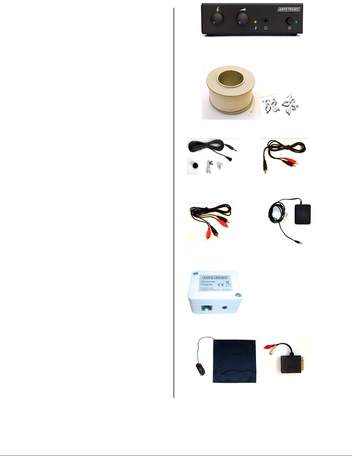
Tools
•Field strength meter (FSM).
•MP3 or CD player with
headphone output.
•Cable 4 (supplied).
•Test signal:
Pink noise with 1 kHz tone.
•Tippex or other semi-
permanent marker.
Method
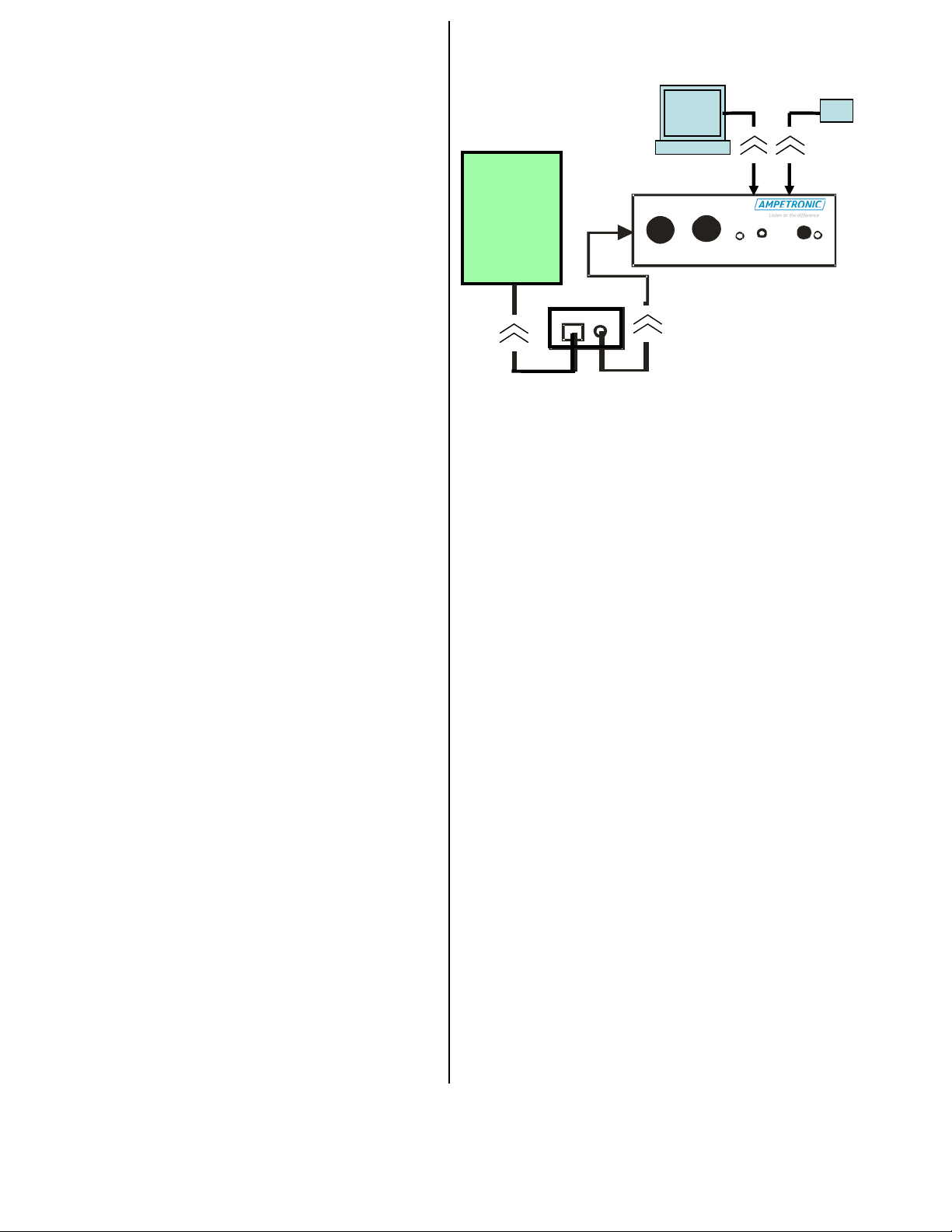
Connect the audio player to input 1
and play test signal 1. The yellow light
3 should illuminate and stay lit. If not,
turn up the volume of the audio player
until the light comes on. (The
compression circuit of the DLS is now
active).
With the field strength meter turned on
and switched to ‘Field Strength’,
measure the field strength at the
typical listening position of the
user, at head height (Possibly a
favourite armchair). Now adjust the
volume control on the DLS until the
meter reading jumps between
readings of -6dB (pink noise playing) and
0dB. (1 kHz sine wave bursts). The field
strength is now set to the IEC60118-4
standard. Mark the position of the volume
control with tippex or other suitable semi-
permanent marker. DO NOT MAKE ANY
FURTHER ADJUSTMENTS TO THIS
CONTROL.
Disconnect the player and connect the
required source(s), TV, HiFi etc., to inputs
1 and 2.
•TO SET UP FIELD STRENGTH
Using the ILR3+ loop listener
Tools
•ILR3+.
•MP3 or CD player with
headphone output.
•Cable 4 (supplied).
•Test signal: Pink noise.
•Tippex or other semi-permanent
marker.
Method
Connect the audio player to input 1 and
play the test track. The yellow light (3)
should illuminate and stay lit. If not, turn
up the volume of the audio player until the
light comes on. (The compression circuit
of the DLS is now active).
With the ILR3+ turned on and volume
setting as required, observe the field
strength at the typical listening position
of the user, at head height (Possibly a
favourite armchair). Now adjust the
volume control on the DLS until the green
and amber LED’s on the ILR3+ flicker
(See ILR3+ user instructions).
Note: ILR3 and ILR3+ audio induction
loop receivers are available from
www.ampetronic.com.