Mitsubishi DX-TL800EZ User manual

1
РУССКИЙ
CASTELLANO
ENGLISHFRANÇAIS
DEUTSCH
DIGITAL RECORDER
OPERATION QUICK GUIDE
MODEL
DX-TL800EZ
THIS INSTRUCTION MANUAL IS IMPORTANT TO YOU. PLEASE READ IT BEFORE USING YOUR DIGITAL RECORDER.

2
••••••••••••••••••••••••••••••••••••••••••••••••••••••••••••••••••••••••••••••••••••••••••••••••••••••••••••••••••••••••••••••••••••••••••••
•
Multplex
&
Record
Digital
TIMER
ENTER/
FF
CLEAR/
REW
M-DET
PRE ALARM LOCK
EMERGENCY
SPLIT/
SEQUENCE ZOOM
ACCESS
REC/STOP
DIGITAL RECORDER DX-TL800E
POWER
56789
1234
10 14131211
89
7
6
5
1234
1. POWER button
When pressing this button while the MAIN switch on
the rear of this unit is set to ON, the power turns on
and the button lights. When the button is pressed
again, the unit will be in standby and the light will
turn off. When the unit is in operational transition
such as booting, the button will flash and other op-
erations are not accepted.
2. ACCESS indicator
Illuminates during access to hard disk drive or Com-
pact Flash Card.
3. Camera number buttons (1 to 9)
Press the button to display the image of the camera
connected to this unit on the monitor.
4. TIMER button
When pressing this button, the unit is set to timer re-
cording/standby and the button flashes. When press-
ing this button for more than 1 second, timer record-
ing/standby is cancelled and the button turns off.
5. REC/STOP button
When pressing this button, recording starts and the
button lights. When pressing the button for more than
1 second, the recording stops and the light turns off.
When pressing this button during alarm recording,
recording stops. During timer recording, recording
will not stop even if the button is pressed.
6. SHUTTLE ring
Used to set various menus and search functions,
adjusting the playback speed, and rewinding or
forwading the image.
7. JOG dial
Used to set various menus and search functions,
forwading or rewinding the image during playback
(field-by-field).
8. SPLIT/SEQUENCE button
Press the button to display SPLIT4 ,SPLIT9 screen
or SEQUENCE screen setting on multiplexer func-
tions.
9. ZOOM button
When pressing this button once during single screen
display, the screen is magnified by 100%. In the same
way, pressing the button twice magnifies the screen
by 200% and pressing the button three times magni-
fies the screen by 400%. During single screen dis-
play, the magnification center point (X) is displayed
on the center of the screen. Pressing a camera
number button (1, 2, 3, or 4) will move the screen
according to the magnification center point as the
axis.
10. PRE ALARM indicator
Illuminate during pre-alarm recording and pre-alarm
recording stand-by mode.
11. M-DET indicator
Illuminates when the motion detection function is on.
The lamp flashes when motion detection is in opera-
tion.
12. EMERGENCY indicator
Flashes during emergency recording and lights when
recording is completed.
13. LOCK indicator
Illuminates when simple lock or password lock is on.
Major operations and their functions
■ Front View

ENGLISH
3
•
••••••••••••••••••••••••••••••••••••••••••••••••••••••••••••••••••••••••••••••••••••••••••••••••••••••••••••••••••••••• QUICK GUIDE
SEARCH
COPY SET UP
VIDEO OUT AUDIO OUT
COMPACTFLASH
STOP PAUSE REV. PLAY PLAY
PLAY
MODE
SHUTTLE
HOLD
16
15 17 18 19 20 21 22
ALARM
INTERRUPT
WARNING
RESET
TIMER
ENTER/
FF
CLEAR/
REW
REC/STOP
M-DET
PRE ALARM EMERGENCY LOCK
SPLIT/
SEQUENCE ZOOM
ACCESS
POWER
56789
1234
14. LOCK button
Pressing it with a pointed object (such as a ball-
point pen) while the MAIN switch (main power) on
the back of the unit is on, will activate the simple
lock. Pressing it for more than 5 seconds will acti-
vate the PASSWORD LOCK SETTING display,
which allows you to designate a PASSWORD. The
indicator will light while the lock is active.
15. ANALOG OUT connectors
VIDEO OUT connector
Output connector for video signal (RCA pin).
AUDIO OUT connector
Output connector for audio signal (RCA pin).
16. COMPACT FLASH slot
Compact Flash Card for saving/loading data and
menus can be used. When not using the slot, at-
tach the COMPACT FLASH slot cover to prevent
dust from entering within the unit.
17. COPY button
Press this button to display <COPY> menu. This
button lights when performing copy operation. The
copy operation cannot be performed if there is no
card in the COMPACT FLASH slot.
18. ALARM INTERRUPT button
When pressing this button, the unit will not accept
alarm signals or motion detection for 5 minutes. Dur-
ing this time, the button will flash.
19. WARNING RESET button
This button is used to clear on-screen warning dis-
play and clear data.
20. SET UP button
Press this button to display the <SETTINGS> menu.
21. SEARCH button
Press this button to display the <SEARCH > menu.
22. OPERATION buttons
STOP button
Press to stop playback.
PAUSE button
When pressing this button during playback, the unit
switches to still frame playback and the button lights.
When pressing this button again, the unit resumes
playback and the button turns off. When pressing
this button during shuttle playback, the set playback
speed is maintained even when letting go of the
SHUTTLE ring.
SHUTTLE HOLD button
This button keeps the particular playback or reverse
playback speed depending on the degree to which
the SHUTTLE ring is turned.
REV. PLAY (REVERSE PLAY) button
When pressing this button, the unit switches to re-
verse playback and the button lights.
PLAY button
When pressing this button, the unit starts playback
and the button lights.
PLAY MODE buttons
These buttons can be used to switch the playback
interval while in playback mode and reverse play-
back mode.
■ Front View (Inside of the door)

4
••••••••••••••••••••••••••••••••••••••••••••••••••••••••••••••••••••••••••••••••••••••••••••••••••••••••••••••••••••••••••••••••••••••••••••
•
Y/C
1
MAIN
OFF
ON
AC IN
~
234 56789
14
RESET
RS-232C
23 56789
1
ALARM IN
2
3
4
5
6
7
8
9
CLOCK ADJ
REC
EMERGENCY
RESERVED
MODE OUT 1
MODE OUT 2
MODE OUT 3
MODE OUT 4
CALL OUT
CALL OUT GND
MAX 30mA
DC 5V OUT
GND
CAMERA OUT
RS-232C
RESET
CAMERA IN
INOUT
VIDEO OUT
MIC
GND
AUDIO
100-240V
12
11
109
876
5
123 4
6. AUDIO connectors
AUDIO IN connector
Input connector for audio signal (RCA pin).
AUDIO OUT connector
Output connector for audio signal (RCA pin).
7. GND terminals
It is the common GND terminal.
8. MIC jack
Input connector for microphone (600 ohm imped-
ance). MIC jack is preferentially inputted to the AU-
DIO IN connector.
9. RESET button
Pressing this button resets the unit and the power
turns off. In this case, video data, menu settings and
the current time are kept.
10. ALARM IN terminals
Input terminal for alarm signal.
11. I/O terminals
CLOCK ADJ terminal
Input terminal to set the present time. Time display
is adjusted to the nearest hour (00 minutes 00 sec-
onds) when this terminal receives the CLOCK ADJ
signal.
INFORMATION
The on-screen clock can be reset to the nearest hour,
by applying a signal to the CLOCK ADJ terminal. For
example, if the current time is 11:29:59, it will be reset
to 11:00:00, and if the current time is 11:30:00, it will be
reset to 12:00:00.
1. MAIN switch
This is the main power switch. When using this unit,
set this switch to ON. Otherwise, the power cannot
be turned on/off using the POWER button on the front
of the unit.
2. VIDEO OUT connectors
VIDEO OUT connector
Output connector for video signal to monitor (BNC
connector).
S(Y/C) OUT connector
These are output connectors for video signals that
separate brightness signals and color signals for
higher picture quality. Simultaneous output along with
VIDEO OUT is also possible.
3. CAMERA IN connectors
Input connector for signal of camera (BNC connector).
4. CAMERA OUT connectors
Camera video output connectors for use of BNC con-
nectors. If the MAIN switch is ON, the through out-
put is possible for the camera image inputted into
each CAMERA IN connector.
5. AC power socket
This socket connects to the power cord. Earth ter-
minal is for safety. Use the 100 ~ 240V plug with
earth for the power of this unit.
If there is no ground terminal on the wall outlet,
contact your dealer of purchase for grounding work
(with charge). When there is no ground terminal in a
wall socket, please request ground construction from
a store. (It is a charge.) Do not connect the earth
terminal of a plug to gas pipe, water pipe, lightning
rod and so on.
Major operations and their functions (continued)
■ Rear View

ENGLISH
5
•
••••••••••••••••••••••••••••••••••••••••••••••••••••••••••••••••••••••••••••••••••••••••••••••••••••••••••••••••••••••• QUICK GUIDE
REC terminal
Input terminal to start recording. Not available dur-
ing timer recording.
EMERGENCY terminal
Input terminal for making it shift to EMERGENCY
recording mode compulsorily.
RESERVED terminal
Not available.
MODE OUT 1 ~ MODE OUT 4 terminals
Output terminal to indicate the unit’s current mode.
Select the unit’s condition by MODE OUT 1 ~ MODE
OUT 4 setting in the <REAR TERMINALSETTINGS>
menu.
CALL OUT terminal / CALL OUT GND terminals
This is the ISOLATION output terminal. Information
that can be transmitted externally consists of CALL
OUT settings made on the <REAR TERMINAL SET-
TINGS> menu screen as well as fixed output set-
tings.
DC 5V OUT terminal
Will only output when both the MAIN switch and
POWER button are ON. The maximum electric cur-
rent is 30mA.
12. RS-232C socket
This terminal is used to connect to host device with
RS-232C terminal. This unit can be controlled by the
other device through this terminal.
■Inserting/Ejecting Compact Flash Card
Before use the Card, read the cautionary notes de-
scribed in the manual included with Compact Flash
Card.
<Inserting Card>
1. Remove the COMPACT FLASH slot cover attached to the
unit.
2. Please turn down the side which contains notch in right and
left, securely insert the Card in the direction of the arrow until
the EJECT button pops out.
Do not eject the Card when copying/restoring, copy-
ing/loading menus, or immediately after inserting the
Card. The Card or the contained data may become
damaged.
Securely insert the Compact Flash Card. Other-
wise, the unit may not work properly.
Please use the Compact Flash Card of an original
format (FSM1) of Mitsubishi. When the Card of a dif-
ferent format from FSM1 is used, there is a possibility
that reading and writing of data may not operate nor-
mally.
When using a new Card, be sure to execute CFC
DATA CLEAR in the <INFORMATION/SERVICE>
screen.
<Ejecting Card>
1. Press the EJECT button and eject the Card.
2. Attach the COMPACT FLASH slot cover.
SEARCH
COPY SET UP
VIDEO OUT AUDIO OUT
COMPACTFLASH
STOP PAUSE REV. PLAY PLAY
PLAY
MODE
SHUTTLE
HOLD
TIMER
ENTER/
FF
CLEAR/
REW
REC/STOP
M-DET
PRE ALARM EMERGENCY LOCK
SPLIT/
SEQUENCE ZOOM
ACCESS
POWER
56789
1234
EJECT Button
COPY
ZOOM
SPLIT/
SEQUENCE
Compact Flash Card
AUDIO OUT
VIDEO OUT

6
•••••••••••••••••••••••••••••••••••••••••••••••••••••••••••••••••••••••••••••••••••••••••••••••••••••••••••••••••••••••••••••••••••••••••••••
•
Basic Operations
■Multiplexer functions
Buttons on the front of the unit can be used to perform
some of the multiplexer functions.
♦Multiplexer buttons
MOVE button
2 SPLIT/SEQUENCE button
3 ZOOM button
1 Camera number buttons (1 to 9)
SPLIT/
SEQUENCE ZOOM
56789
1234
1. Camera number buttons (1 to 9)
Video images of cameras connected to CAMERA IN ter-
minals 1 to 9 on the rear of the unit are displayed.
By pressing a camera number button, video
image can be displayed even if the camera is not
set for recording.
2. SPLIT/SEQUENCE button
The screen switches in order of SPLIT9, 3 types of SPLIT4
SCREEN SETTING (a, b, c), SPLIT4 SEQUENTIAL, and
SINGLE SEQUENTIAL set in the <MPX DISPLAY SET-
TING> screen (SEQUENTIAL display is skipped during
playback).
3. ZOOM button
When this button is pressed during single screen display,
MAGNIFICATION 100% screen appears and the magnifi-
cation centre point (X) is displayed at the centre. Pressing
the button again will switch the magnification to 200% and
then 400%. By pressing the MOVE buttons, the magnified
screen can be moved vertically/horizontally with the cen-
tre point as the axis.
When the ZOOM button is pressed, camera number
buttons 1 ~ 4 switches to the MOVE buttons.
■ Menu settings
The operational conditions of this unit can be set in the
menu screens according to use. Although the setting
method will differ slightly depending on the menu screen,
the basic setting method of using the JOG dial and SHUT-
TLE ring will be used for setting the display mode as an
example.
SHUTTLE ring
JOG dial
Example : Set DISPLAY MODE to “3”( default : “1”).
1. Set the MAIN switch on the rear of the unit to ON. Press
the POWER button on the front after the ACCESS indicator
turns off.
• “SETTING UP...” appears on the screen and the unit is
booted.
• POWER button operation will not be accepted while the
ACCESS indicator is flashing. Press the POWER button after
the indicator turns off.
2. After boot-up, press a SET UP button inside the door on
the front of the unit.
• The <SETTINGS> screen appears.
<SETTINGS>
>>
TIME DATE/DISPLAY SETTINGS
MPX DISPLAY SETTINGS
MOTION DETECTION SETTINGS
RECORD SETTINGS
TIMER PROGRAM SETTINGS
INITIAL SET UP/INFORMATION
QUICK SETTINGS
MEMO:
When a SET UP button is pressed and the menu
screen appears, the background darkens and the
displayed characters become easier to see.
3. Check to see that the cursor (>>) is positioned at “TIME
DATE/DISPLAY SETTINGS”, and then turn the SHUTTLE ring
clockwise.
• The <TIME DATE/DISPLAY SETTINGS> screen appears.
<TIME DATE/DISPLAY SETTINGS>
>>
TIME DATE ADJUST
DISPLAY MODE 1
CLOCK LOCATION SETTING
CAMERA DISPLAY NUMBER
CAMERA TITLE/MEMO SETTING
DUPLEX MODE DISPLAY BOTTOM
<MODE1>
01-01-2002 00:00:00
4. Turn the JOG dial to move the cursor to “DISPLAY MODE”
and turn the SHUTTLE ring clockwise.
• The background of the “DISPLAY MODE” setting turns red
and flashes.
When turning the JOG dial clockwise, the cursor
(>>) moves down. When turning counterclockwise,
the cursor (>>) moves up.
5. Turn the JOG dial to display “3”.
• The display mode sample on the bottom of the screen
changes to <MODE3>.
6. Turn the SHUTTLE ring clockwise.
• The setting is confirmed and flashing stops.
• To continue with other settings, repeat steps 4 and 5.
When turning the SHUTTLE ring counterclockwise
while the setting is flashing, the setting will return to
the previous setting. To exit the screen, turn the SHUT-
TLE ring counterclockwise.
<TIME DATE/DISPLAY SETTINGS>
TIME DATE ADJUST
>>
DISPLAY MODE
CLOCK LOCATION SETTING
CAMERA DISPLAY NUMBER
CAMERA TITLE/MEMO SETTING
DUPLEX MODE DISPLAY BOTTOM
<MODE >
01-01-2002 TUE
00:00:00 12.5P 99
%
A00001

7
•
•••••••••••••••••••••••••••••••••••••••••••••••••••••••••••••••••••••••••••••••••••••••••••••••••••••••••••••••••••••• QUICK GUIDE
ENGLISH
♦To return to the normal screen from a menu screen
The procedure to return to the normal screen after com-
pleting menu screen settings using the JOG dial/SHUT-
TLE ring is explained.
1. Check to see that the setting item is no longer flashing and
the item has been changed to the desired setting.
• The setting has not been confirmed if the item is flashing.
Refer to the above setting procedure to confirm the setting.
• To continue with other settings or to check the setting item,
turn the SHUTTLE ring counterclockwise once to return to
the previous screen.
This operation is not accepted when the setting
item is flashing.
2-1. (To return to the normal screen by moving up menu
screens one at a time •••)
• Turn the SHUTTLE ring counterclockwise for the amount of
menu screens opened. The previous menu screen is
displayed every time the SHUTTLE ring is turned
counterclockwise.
2-2. (To directly return to the normal screen •••)
• Press the SET UP button to clear the menu screen and return
to the normal screen.
The menu screen will not be cleared even when
pressing the SET UP button when the setting item
is flashing.
♦DAYLIGHT SAVING
The clock is put forward one hour by setting the menu. The
default setting for this function is “OUT”. On the DAYLIGHT
SAVING in <TIME DATE ADJUST> menu, turn the JOG
dial to flash “IN”(the daylight saving function is activating)
and turn the SHUTTLE ring clockwise to enter the selec-
tion.
♦TIME DATE ADJUST
Before starting recording, it is necessary to set
accurately the current date and time.
Example : Set the date/time to 28/10/2002 6:30pm
(18:30)( default : “01/01/2002 00:00:00”).
1. Press the SET UP button to display the <SETTINGS>
screen.
2. Check to see that the cursor (>>) is positioned at “TIME
DATE/DISPLAY SETTINGS”, and then turn the SHUTTLE ring
clockwise.
• The <TIME DATE/DISPLAY SETTINGS> screen appears.
3. Check to see that the cursor is positioned at “TIME DATE
ADJUST”, and then turn the SHUTTLE ring clockwise.
• The <TIME DATE ADJUST> screen appears.
<TIME DATE ADJUST>
>>
DAYLIGHT SAVING OUT
DAY 01
MONTH 01
YEAR 2002
TIME 00:00:00
4. Turn the JOG dial to move the cursor to “DAY”and turn the
SHUTTLE ring clockwise.
• The background of “DAY” changes to red and flashes.
<TIME DATE ADJUST>
DAYLIGHT SAVING OUT
>>
DAY 01
MONTH 01
YEAR 2002
TIME 00:00:00
5. Turn the JOG dial to display “28”and turn the SHUTTLE
ring clockwise.
• The setting is confirmed and flashing stops.
<TIME DATE ADJUST>
DAYLIGHT SAVING OUT
>>
DAY 28
MONTH 01
YEAR 2002
TIME 00:00:00
6. Turn the JOG dial clockwise to move the cursor (>>) to
“MONTH”.
When turning the JOG dial clockwise, the cursor
(>>) moves down. When turning counterclockwise,
the cursor (>>) moves up.
7. Repeat steps 4 ~ 6 to set “MONTH”and “YEAR”.
8. Turn the JOG dial to move the cursor (>>) to “TIME”and
turn the SHUTTLE ring clockwise twice.
• The “TIME” display reverses in color when the SHUTTLE
ring is turned the first time. When the ring is turned for the
second time, the display turns red and flashes.
<TIME DATE ADJUST>
DAYLIGHT SAVING OUT
DAY 28
MONTH 10
YEAR 2002
>>
TIME 00:00:00
9. Turn the JOG dial to display “18”and turn the SHUTTLE
ring clockwise.
• The setting is confirmed and flashing stops.
<TIME DATE ADJUST>
DAYLIGHT SAVING OUT
DAY 28
MONTH 10
YEAR 2002
>>
TIME 18:00:00
The time is indicated using the 24-hour system.
10. Repeat steps 8 and 9 to set “MINUTE”and “SECOND”.
11. Turn the SHUTTLE ring clockwise.
• The setting is confirmed and flashing stops.
<TIME DATE ADJUST>
DAYLIGHT SAVING OUT
DAY 28
MONTH 10
YEAR 2002
>>
TIME 18: 0:00
12. Turn the SHUTTLE ring counterclockwise or press the SET
UP button.

8
•••••••••••••••••••••••••••••••••••••••••••••••••••••••••••••••••••••••••••••••••••••••••••••••••••••••••••••••••••••••••••••••••••••••••••••
•
Basic Operations (continued)
Relation between a number of operation cameras and a “PPS”
25P
12.5P
8.333P
6.25P
5P
4.167P
3.125P
2.5P
1P
0.5P
0.25P
0.125P
12.5P
6.25P
4.167P
3.125P
2.5P
2.083P
1.563P
1.25P
0.5P
0.25P
0.125P
0.063P
8.333P
4.167P
2.778P
2.083P
1.667P
1.389P
1.042P
0.833P
0.333P
0.167P
0.083P
0.042P
6.25P
3.125P
2.083P
1.563P
1.25P
1.042P
0.781P
0.625P
0.25P
0.125P
0.063P
0.031P
5P
2.5P
1.667P
1.25P
1P
0.833P
0.625P
0.5P
0.2P
0.1P
0.05P
0.025P
4.167P
2.083P
1.389P
1.042P
0.833P
0.694P
0.521P
0.417P
0.167P
0.083P
0.042P
0.021P
3.571P
1.786P
1.19P
0.893P
0.714P
0.595P
0.446P
0.357P
0.143P
0.071P
0.036P
0.018P
3.125P
1.563P
1.042P
0.781P
0.625P
0.521P
0.391P
0.313P
0.125P
0.063P
0.031P
0.016P
2.778P
1.389P
0.926P
0.694P
0.556P
0.463P
0.347P
0.278P
0.111P
0.056P
0.028P
0.014P
Number of
operation
cameras
PPS
SHORT
Recording
interval
LONG
# 1 # 2 # 3 # 4 # 5 # 6 # 7 # 8 # 9
Settings here are for normal recording only. For
timer recording, settings must be made on the
<TIMER PROGRAM SETTINGS> screen.
♦Settingtherecordinginterval and recording picture
quality for normal recording
To perform normal recording, “PPS”and “GRADE”must
be set for each camera.
Setting of “PPS”( default : “1.389P”)
“2.778P”, “1.389P”, “0.926P”, “0.694P”, “0.556P”,
“0.463P”, “0.347P”, “0.278P”, “0.111P”, “0.056P”,
“0.028P”, “0.014P”, “- - - - -”
“- - - - -”: Recording cannot be performed with cam-
era set to this item.
Available recording intervals will vary according
to the number of cameras operating or ALARM RE-
CORDING settings. Interval displays will be accord-
ing to the chart below.
Setting of “GRADE”( default : “STD”)
“SUPER”, “HIGH”, “STD”(STANDARD), “BASIC”,
“LONG”
Example : Set “PPS”of camera number “
1
”to “0.556P”
and “GRADE”to “HIGH”for normal recording.
1. Press the SET UP button to display the <SETTINGS>
screen.
2. Turn the JOG dial to move the cursor to “RECORD
SETTINGS”and turn the SHUTTLE ring clockwise.
•The <RECORD SETTINGS> screen appears.
<RECORD SETTINGS>
>>
RECORD SETTING
ALARM REC DURATION 5S
PRE ALARM REC OFF
♦Present time display
When turning on the unit power, the time/date display shown
below appears (in the case of DISPLAY MODE3).
During recording, the used HDD space is dis-
played. When recording is stopped, the display is
cleared (with the exception of when pausing record-
ing). The HDD usage display appears again after a
few moments when recording is started once more.
INFORMATION
This unit uses 4 digits to display the year. The al-
lowed display range is 99 years between 1/1/2001
~ 31/12/2099. The unit is also equipped with a func-
tion to automatically calculate leap years. The date
returns to the year 2001 after 31/12/2099.
01 - 01 - 2002
TUE
00 : 00 : 00 12.5P 99% A00001
Year
Month
Day Day of
the week
Alarm recording number
Minute
Second
Hour
Recording interval
Recorded capacity of
the Hard Disk
♦Recorded capacity display function
This unit displays the used space of the specified record-
ing device (HDD) on the screen when “REMAIN HDD”of
the <REAR TERMINALSETTINGS> screen is set to “HDD”.
The “%”indicates the ratio detected as HDD against the
total HDD capacity. The following settings are required to
enable this function.
1) Select the device and set the remaining capacity using
“REMAIN HDD”of the <REAR TERMINAL SETTINGS>
screen.
2) Select “3”for “DISPLAY MODE”in the <TIME DATE/
DISPLAY SETTINGS> screen.
■Basic manual recording
Normal recording using manual operation is explained here.
Before starting recording, recording settings must be
checked. After checking the settings of “HDD REPEAT
REC”in the <HDD SETTINGS> screen, the REC mode
settings are made.

9
•
•••••••••••••••••••••••••••••••••••••••••••••••••••••••••••••••••••••••••••••••••••••••••••••••••••••••••••••••••••••• QUICK GUIDE
ENGLISH
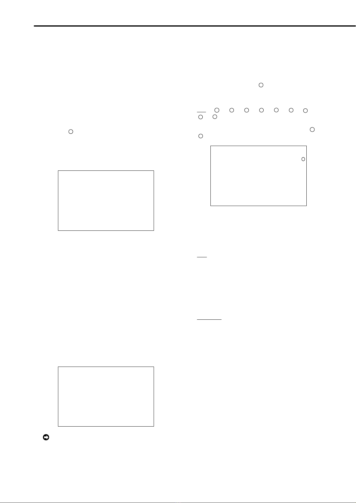
3. Check to see that the cursor is positioned at “RECORD
SETTING”, and then turn the SHUTTLE ring clockwise.
•The <RECORD SETTING> screen appears.
9
7
4
5
6
1
2
3
8
<RECORD SETTING> ALARM PLUS
NO.PPS GRADE A-PPS A-GRADE
>>
1. 89P STD 1. 89P STD
<ESTD TIME> H M
Camera selection during alarm recording
4. Check to see that the cursor is positioned at “
1
”, and
then turn the SHUTTLE ring clockwise.
•The “PPS”setting reverses in color.
4
1
2
3
<RECORD SETTING> ALARM PLUS
NO.PPS GRADE A-PPS A-GRADE
1. 89P STD 1. 89P STD
1 89P STD 1 89P STD
5. Turn the SHUTTLE ring clockwise again.
•The background of the “PPS”setting turns red and flashes.
1
2
3
<RECORD SETTING> ALARM PLUS
NO.PPS GRADE A-PPS A-GRADE
1. 89P STD 1. 89P STD
The menu screen will not be cleared even when
pressing the SET UP button when the setting item
is flashing.
6. Turn the JOG dial to select “0.556P”and turn the SHUTTLE
ring clockwise.
•Setting is confirmed and flashing stops.
1
2
3
<RECORD SETTING> ALARM PLUS
NO.PPS GRADE A-PPS A-GRADE
0.556P STD 1. 89P STD
1. 89P STD 1. 89P STD
7. Turn the JOG dial clockwise to reverse display “GRADE”
and turn the SHUTTLE ring clockwise.
•The background of the “GRADE”setting turns red and
flashes.
1
2
3
<RECORD SETTING> ALARM PLUS
NO.PPS GRADE A-PPS A-GRADE
0.556P STD 1. 89P STD
1. 89P STD 1. 89P STD
When the setting item is flashing, the menu
screen cannot be cleared even when pressing the
SET UP button.
8. Turn the JOG dial to select “HIGH”and turn the SHUTTLE
ring clockwise.
•The setting is confirmed and flashing stops.
1
2
3
<RECORD SETTING> ALARM PLUS
NO.PPS GRADE A-PPS A-GRADE
0.556P HIGH 1. 89P STD
1. 89P STD 1. 89P STD
About <ESTD TIME>
•The remaining recordable time is displayed as <ESTD TIME>
depending on the “PPS”and “GRADE”settings (The time will
not change when changing the alarm recording settings) .
9. When completed with setting, turn the SHUTTLE ring
counterclockwise.
•The cursor moves to the camera number on the left.
•When continuing with other camera number settings, turn
theJOG dial to move the cursor to the desired camera number
and repeat steps 4 ~ 8 to perform settings.
4
1
2
3
<RECORD SETTING> ALARM PLUS
NO.PPS GRADE A-PPS A-GRADE
>>
0.556P HIGH
1. 89P STD
1. 89P STD 1. 89P STD
1 89P STD 1 89P STD
10. Turn the SHUTTLE ring counterclockwise or press the SET
UP button to return to the normal screen.
11. Press the REC/STOP button.
•REC/STOP button light turns on and recording starts.
12. To stop recording, press the REC/STOP button for more
than 1 second.
•Recording stops and the REC/STOP button light turns off.
REC/STOP
■Basic playback
This unit allows recorded video to be played back using
various methods. The basic playback described here is the
most common method for playback.
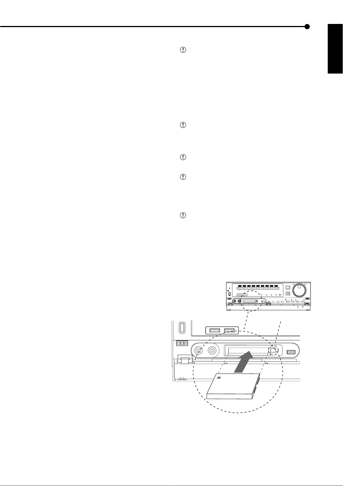
1. Press the PLAY button within the door on the front of the unit.
•Recorded contents of the HDD are played back.
•After turning the power on, the oldest recorded video is
playedback first. Otherwise, playback resumes at theposition
of the previous playback.
STOP PAUSE REV. PLAY PLAY
When the “HDD REPEAT PLAY”setting in the
“HDD SETTINGS”is set to “OFF”, playback is
stopped when reaching the end of the physical HDD
or recorded section. When the “HDD REPEAT PLAY”
setting is set to “ON”, recorded video data is played
back repeatedly.
1-1. Changing the playback device.
•The default setting of the playback device is HDD.
•When changing the playback device to Compact Flash Card,
press the SEARCH button twice to display the <SEARCH
SELECTION> screen and select “CFC”(Compact Flash Card)
in “PLAYBACK DEVICE”.
2. To pause playback, press the PAUSE button.
•To resume playback, press the PAUSE button again or press
the PLAY button.
3. To stop playback, press the STOP button.
•During HDD playback/pause, playback will start the next
time from the paused position.
•During CFC playback/pause, playback will start the next time
from the oldest recorded video on the media.

10
•••••••••••••••••••••••••••••••••••••••••••••••••••••••••••••••••••••••••••••••••••••••••••••••••••••••••••••••••••••••••••••••••••••••••••••
•
Basic Operations (continued)
■Basic search
This unit displays a menu of most used search functions
simply by pressing the SEARCH button.
♦TIME DATE SEARCH
On this unit, various search functions are available for
searching the beginning of video clips. In this section, the
most common search method referred to as time/date
search is explained. With this method, searching is possi-
ble by date, hour, minute, second and specified camera
number.
Example : Search a scene recorded on the HDD with time/
date stamp of 03/03/2002 9:25:40pm (21:25:40) using cam-
era number “
3
”.
1. Press the SEARCH button to display the <TIME DATE
SEARCH> screen.
•The default setting of the search menu displayed when
pressing the SEARCH button is “TIME DATE SEARCH”.
<TIME DATE SEARCH>
>>
01-01-2002 00:00:00
EXECUTE(FORWARD)
START 02-02-2002 00:00:00
END 04-04-2002 12: 0:15
PUSH SEARCH KEY FOR
SEARCH SELECTION
2. Check to see that the cursor is next to the search date and
turn the SHUTTLE ring clockwise twice.
•The display reverses in color when the SHUTTLE ring is
turned the first time. When the ring is turned for the second
time, the display turns red and flashes.
3. Turn the JOG dial to display “03”for “DAY”and turn the
SHUTTLE ring clockwise.
•Setting is confirmed and flashing stops.
4. Turn the JOG dial to reverse display “MONTH”and turn the
SHUTTLE ring clockwise.
•The background of the setting item changes to red and
flashes.
5.Turn the JOG dial to display “03”for “MONTH”and turn the
SHUTTLE ring clockwise.
•Setting is confirmed and flashing stops.
6. Repeat steps 4 and 5 to set “YEAR”, “HOUR”, “MINUTE”
and “SECOND”.
<TIME DATE SEARCH>
>>
0 -0 -2002 21:25:40
EXECUTE(FORWARD)
START 02-02-2002 00:00:00
END 04-04-2002 12: 0:15
PUSH SEARCH KEY FOR
SEARCH SELECTION
To exit the <TIME DATE SEARCH> screen with-
out searching, turn the SHUTTLE ring
counterclockwise or press the SEARCH button twice.
7. Press the SEARCH button to display the <SEARCH
SELECTION> screen.
8. Check to see that the cursor is positioned at “SELECTION
CAMERA NO. ”, and then turn the SHUTTLE ring clockwise.
•The background of the setting item changes to red and
flashes.
9. Turn the JOG dial to select “
3
”and turn the SHUTTLE ring
clockwise.
•Setting is confirmed and flashing stops.
•Setting ( default : “ALL”)
“ALL”, “
1
”, “
2
”, “
3
”, “
4
”, “5”, “
6
”, “
7
”,
“
8
”, “
9
”
“ALL”: Search is conducted for all camera number “
1
”~
“
9
”.
<SEARCH SELECTION>
SEARCH TYPE TIME DATE
>>
SELECTION CAMERA NO.
PLAYBACK DEVICE HDD
START 02-02-2002 00:00:00
END 04-04-2002 12: 0:15
3
10-1. (To change the playback device •••)
Turn the JOG dial to select “PLAYBACK DEVICE”and turn
the SHUTTLE ring clockwise.
•The background of the setting item changes to red and
flashes. Turn the JOG dial to display the desired playback
device and confirm.
•Setting ( default : “HDD”)
“HDD”: Select when playing back HDD contents.
“CFC”: Select when playing back Compact Flash Card
contents.
10-2. (To change the search type •••)
Turn the JOG dial to select “SEARCH TYPE”and turn the
SHUTTLE ring clockwise.
•The background of the setting item changes to red and
flashes. Turn the JOG dial to display the desired search menu
and confirm.
•Setting ( default : “TIME DATE”)
“TIME DATE”, “INDEX”, “ALARM INDEX”, “ALARM SKIP”,
“ALARM LIST”
11. When completed with setting, turn the SHUTTLE ring
counterclockwise.
•The display returns to the <TIME DATE SEARCH> screen
and the cursor appears on the left of the search date.
12. Turn the JOG dial to select “EXECUTE(FORWARD)”and
turn the SHUTTLE ring clockwise.
•The TIME DATE SEARCH begins the video of the set date/
time (or the video closest to the search) will appear in still
frame.
•The search result will appear using SPLIT9 screen when
“ALL”is selected in “SELECTION CAMERA NO.”of the
“SEARCH SELECTION”screen. If camera number has been
selected individually, the still frame will be displayed in a
single screen.

11
•
•••••••••••••••••••••••••••••••••••••••••••••••••••••••••••••••••••••••••••••••••••••••••••••••••••••••••••••••••••••• QUICK GUIDE
ENGLISH
<TIME DATE SEARCH>
>>
0 -0 -2002 21:25:40
EXECUTE(FORWARD)
START 02-02-2002 00:00:00
END 04-04-2002 12: 0:15
PUSH SEARCH KEY FOR
SEARCH SELECTION
When there is no recording of the set time, the
video of the close time and date for the set camera
number will be displayed in still frame.
Depending on the recording condition, TIME
DATE SEARCH may not operate correctly.
To display a single screen by selecting a camera
number from the SPLIT9 screen of the search re-
sult when “ALL”is selected in the “SELECTION
CAMERA NO.”setting, press the SEARCH button
to clear the SEARCH menu and press the desired
camera number button. The desired video is dis-
played in single screen.
13. To playback the searched image.
•Press either the PLAY button or the PAUSE button.
14. To stop playback/still frame playback, press the STOP button.
•The display returns to the normal screen.
15. Press the SEARCH button to clear the <SEARCH
SELECTION> screen.
0 -0 -2002 21:25:40
3
PLAY

12
•••••••••••••••••••••••••••••••••••••••••••••••••••••••••••••••••••••••••••••••••••••••••••••••••••••••••••••••••••••••••••••••••••••••••••••
•
■ Continuous recording time table
♦HDD continuous recording time (for 120GB drive)
Displays the estimated recordable time (when recording on a 120GB HDD).
The following recording time table is only for when operating with one camera and the recording interval is set
the same.
•Without Audio recording
PPS
GRADE
SUPER
HIGH
STD
BASIC
LONG
25P 12.5P 8.333P 6.25P 5P 4.167P 3.125P 2.5P 1P 0.5P 0.25P 0.125P
NUMBER OF
RECORDING
FIELD
28h
37h
60h
85h
188h
56h
74h
120h
170h
377h
84h
111h
181h
255h
566h
112h
148h
241h
340h
755h
140h
185h
302h
425h
944h
168h
222h
362h
510h
1133h
224h
297h
483h
681h
1510h
280h
371h
604h
851h
1888h
702h
929h
1512h
2128h
4720h
1404h
1858h
3024h
4256h
9441h
2808h
3716h
6049h
8512h
18883h
5617h
7432h
12099h
17025h
37767h
2,566,000
3,383,000
5,483,000
7,700,000
17,034,000
•With Audio recording <Audio recording using 12.8KHz PCM sampling is possible.>
PPS
GRADE
SUPER
HIGH
STD
BASIC
LONG
25P 12.5P 8.333P 6.25P 5P 4.167P 3.125P 2.5P 1P 0.5P 0.25P 0.125P
h : hour
26h
35h
59h
82h
165h
53h
71h
115h
159h
325h
80h
103h
169h
232h
457h
107h
138h
221h
299h
573h
127h
172h
270h
360h
678h
152h
199h
316h
417h
775h
203h
255h
401h
535h
929h
242h
319h
488h
630h
1058h
541h
669h
929h
1123h
1609h
892h
1019h
1339h
1534h
1922h
2808h
3716h
6049h
8512h
18883h
5617h
7432h
12099h
17025h
37767h
Continuous recordable time and the estimated time displayed on the menu screen is the continuous record-
able time when operating this unit and is not the product warranty period. Furthermore, it is not the period that
guarantees the operation of used parts.
Audio recording cannot be performed when “PPS”of “RECORD SETTING”are all set to smaller than “0.333P”
when setting normal recording.
•In this case, ( X ) appears to the right of <ESTD TIME>.
•When the camera selection during for alarm recording is as follows :
“ALL”, “ALARM”: “A-PPS”of all cameras set for alarm recording are set to smaller than “0.333P”.
“ALARM PLUS”: “PPS”and “A-PPS”of all cameras set for normal recording and alarm recording are set to
smaller than “0.333P”.
: Since audio recording cannot be made during recording interval of 0.25P and 0.125P, even when the
recording with audio recording set to ON, the recording time table is the same for when setting audio recording to
OFF.
Recording time table

13
•
••••••••••••••••••••••••••••••••••••••••••••••••••••••••••••••••••••••••••••••••••••••••••••••••••••••••••••••••••••••• QUICK GUIDE
ENGLISH
Menu functions
9
7
4
5
6
1
2
3
8
9
7
4
56
1
2
3
8
1
2
3
9
7
456
1
2
3
8
9
7
4
5
6
1
2
3
8
<SETTINGS>
>>
TIME DATE/DISPLAY SETTINGS
MPX DISPLAY SETTINGS
MOTION DETECTION SETTINGS
RECORD SETTINGS
TIMER PROGRAM SETTINGS
INITIAL SET UP/INFORMATION
QUICK SETTINGS
MEMO:
<TIME DATE/DISPLAY SETTINGS>
>>
TIME DATE ADJUST
DISPLAY MODE 1
CLOCK LOCATION SETTING
CAMERA DISPLAY NUMBER
CAMERA TITLE/MEMO SETTING
DUPLEX MODE DISPLAY BOTTOM
<MODE1>
01-01-2002 00:00:00
<TIME DATE ADJUST>
>>
DAYLIG T SAVING OUT
DAY 01
MONT 01
YEAR 2002
TIME 00:00:00
••01-01-2002•00:00:00•••••••••••
••••••••••••••••••••••••••••••••
••••••••••••••••••••••••••••••••
••••••••••••••••••••••••••••••••
••••••••••••••••••••••••••••••••
••••••••••••••••••••••••••••••••
••••••••••••••••••••••••••••••••
••••••••••••••••••••••••••••••••
••••••••••••••••••••••••••••••••
••••••••••••••••••••••••••••••••
••••••••••••••••••••••••••••••••
••••••••••••••••••••••••••••••••
<CAMERA TITLE/MEMO SETTING>
>>
••••••••••••••••
••••••••••••••••
••••••••••••••••
••••••••••••••••
••••••••••••••••
••••••••••••••••
••••••••••••••••
••••••••••••••••
••••••••••••••••
MEMO ••••••••••••••••
>S UTTLE>>:C ARACTERS
<C ARACTERS>
••••••••••••••••
!
" #
$
%
& ' (
)
+ ,
-
.
/
: ;
<
=
>?
@
•••••••
0123456789••••••••••••••••••••
ABCDEFG IJKLMNOPQRSTUVWXYZ••••
abcde
f
gh
i
j
k
l
mnopqrs
t
uvwxyz
••••
S UTTLE<<:GO BACK
<MPX DISPLAY SETTINGS>
>>
SPLIT4 SCREEN SETTING
SPLIT9 SCREEN SETTING
SEQUENCE SETTING
INTERLASE ON
<SPLIT4 SCREEN SETTING>
>>
SPLIT4(a) SPLIT4(b)
( ) ( ) ( ) ( )
( ) ( ) ( ) ( )
SPLIT4(c)
( ) ( )
( ) ( )
<SPLIT9 SCREEN SETTING>
>>
SPLIT9
( ) ( ) ( )
( ) ( ) ( )
( ) ( ) ( )
<SEQUENCE SETTING>
SEQUENCE NUMBER TIME
>>
1 1S
2 1S
3 1S
4 1S
5 1S
6 1S
7 1S
8 1S
9 1S
SPLIT4 abc 1S
SET UP
SUB MENU (1)
<TIME DATE/DISPLAY SETTINGS> <TIME DATE ADJUST>
MAIN MENU SUB MENU (2)
<CLOCK LOCATION SETTING>
<CAMERA TITLE/MEMO SETTING>
<SPLIT4 SCREEN SETTING>
<CHARACTERS>
<MPX DISPLAY SETTINGS>
<SPLIT9 SCREEN SETTING>
<SEQUENCE SETTING>
■ MENU SETTING
You can set the basic settings for this unit in the MENU SETTING.
During playback, recording, pre-alarm recording stand-by mode you cannot change setting of some MENUs.

14
••••••••••••••••••••••••••••••••••••••••••••••••••••••••••••••••••••••••••••••••••••••••••••••••••••••••••••••••••••••••••••••••••••••••••••
•
Menu functions (continued)
9
7
4
5
6
1
2
3
8
9
7
4
5
6
1
2
3
8
1
• • •••••••••• ••••
• • •••••••••• ••••
• • •••••••••• ••••
• • •••••••••• ••••
• • •••••••••• ••••
• • •••••••••• ••••
• • •••••••••• ••••
• • •••••••••• ••••
• • •••••••••• ••••
• • •••••••••• ••••
• • •••••••••• ••••
• • •••••••••• ••••
<MOTION DETECTION SETTINGS>
>>
SELECTION CAMERA NUMBER
MOTION DETECTION OFF
DETECTION MASK SETTING
SENSITIVITY IG ••<<<LOW
MOTION T RES OLD 1
TEST MODE
<RECORD SETTINGS>
>>
RECORD SETTING
ALARM REC DURATION 5S
PRE ALARM REC OFF
<RECORD SETTING> ALARM PLUS
NO.PPS GRADE A-PPS A-GRADE
>>
1.389P STD 1.389P STD
<ESTD TIME> M
<TIMER PROGRAM SETTINGS>
>>
SELECTED PATTERN P1-SET
OLIDAY SETTING
REC MODE A NORMAL
&
ALARM-SET
REC MODE B NORMAL
&
ALARM-SET
REC MODE C NORMAL
&
ALARM-SET
REC MODE D NORMAL
&
ALARM-SET
ALARM REC DURATION 5S
PRE ALARM REC S ORT
<REC MODE A> ALARM PLUS
NO.PPS GRADE A-PPS A-GRADE
>>
1.389P STD 1.389P STD
<ESTD TIME> M
<TIMER PROGRAM> P1
DW START END MODE M-DET
>>
1 --- --:-- --:-- ---- ---
2 --- --:-- --:-- ---- ---
3 --- --:-- --:-- ---- ---
4 --- --:-- --:-- ---- ---
5 --- --:-- --:-- ---- ---
6 --- --:-- --:-- ---- ---
7 --- --:-- --:-- ---- ---
8 --- --:-- --:-- ---- ---
SPL SAT-SUN
< OLIDAY SETTING>
--/-- --/-- --/-- --/--
--/-- --/-- --/-- --/--
--/-- --/-- --/-- --/--
--/-- --/-- --/-- --/--
--/-- --/-- --/-- --/--
DAY/MONT
& & &&&&&&&&&& &&&&
& & &&&&&&&&&& &&&&
& & &&&&&&&&&& &&&&
& & &&&&&&&&&& &&&&
& & &&&&&&&&&& &&&&
& & &&&&&&&&&& &&&&
& & &&&&&&&&&& &&&&
& & &&&&&&&&&& &&&&
& & &&&&&&&&&& &&&&
& & &&&&&&&&&& &&&&
& & &&&&&&&&&& &&&&
& & &&&&&&&&&& &&&&
<SETTINGS>
>>
TIME DATE/DISPLAY SETTINGS
MPX DISPLAY SETTINGS
MOTION DETECTION SETTINGS
RECORD SETTINGS
TIMER PROGRAM SETTINGS
INITIAL SET UP/INFORMATION
QUICK SETTINGS
MEMO:
SUB MENU (1)
MAIN MENU SUB MENU (2)
SET UP
<DETECTION MASK SETTING>
<TEST MODE>
<MOTION DETECTION SETTINGS>
<RECORD SETTINGS> <RECORD SETTING>
<TIMER PROGRAM>
<HOLIDAY SETTING>
<TIMER PROGRAM SETTINGS>
<REC MODE A> ~ <REC MODE D>

15
•
••••••••••••••••••••••••••••••••••••••••••••••••••••••••••••••••••••••••••••••••••••••••••••••••••••••••••••••••••••••• QUICK GUIDE
ENGLISH
<QUICK SETTINGS>
>>
LOAD SETTING DATA FROM CFC
SAVE SETTING DATA TO CFC
<INITIAL SET UP/INFORMATION>
>>
DD SETTINGS
AUDIO RECORDING OFF
REAR TERMINAL SETTINGS
RS-232C
INFORMATION/SERVICE
< DD SETTINGS>
>>
DD REPEAT REC OFF
DD REPEAT PLAY OFF
IM-C ECK PLAY OFF
SEQUENTIAL PLAY OFF
<REAR TERMINAL SETTINGS>
>>
MODE OUT 1 OFF
MODE OUT 2 OFF
MODE OUT 3 OFF
MODE OUT 4 OFF
KEY SOUND ON
BUZZER REMAIN
REMAIN DD DD-10
%
CALL OUT SETTINGS
EMERGENCY REC DURATION 10M
<CALL OUT SETTINGS>
>>
DD REMAIN OFF
DD FULL OFF
<RS-232C>
>>
MODE REMOTE A
SETTINGS
<RS-232C SETTINGS>
>>
TRANSMISSION MODE 1200
DATA BIT LENGT 8BIT
PARITY BIT NONE
STOP BIT LENGT 1BIT
DELIMITER CR
<INFORMATION>
CFC
CAPACITY 64MB
MENU INFORMATION
START ---------- --:--:--
END ---------- --:--:--
<INFORMATION/SERVICE>
>>
DD INFORMATION
CFC INFORMATION
WARNING LOG LIST
SETTING DATA INITIALIZE
DD DATA CLEAR
CFC DATA CLEAR
ELAPSED TIME 10
<WARNING LOG LIST>
NO DATE TIME WARNING
>>
0001 01-01-02 00:00:00 ALM ON
<INFORMATION>
DD
MASTER DD(120GB)
SLAVE NONE
START ---------- --:--:--
END ---------- --:--:--
< DD DATA CLEAR>
PUS WARNING RESET KEY
FOR 1 SECOND TO CLEAR
<CFC DATA CLEAR>
PUS WARNING RESET KEY
FOR 1 SECOND TO CLEAR
<SETTINGS>
>>
TIME DATE/DISPLAY SETTINGS
MPX DISPLAY SETTINGS
MOTION DETECTION SETTINGS
RECORD SETTINGS
TIMER PROGRAM SETTINGS
INITIAL SET UP/INFORMATION
QUICK SETTINGS
MEMO:
<SETTING DATA INITIALIZE>
>>
EXECUTE
S UTTLE>>:EXECUTE,<<:CANCEL
SUB MENU (1)
MAIN MENU
SET UP
SUB MENU (2) SUB MENU (3)
<INITIAL SET UP/INFORMATION> <HDD SETTINGS>
<REAR TERMINAL SETTINGS> <CALL OUT SETTINGS>
<RS-232C>
<INFORMATION/SERVICE>
<RS-232C SETTINGS>
<SETTING DATA INITIALIZE>
<INFORMATION> (HDD)
<INFORMATION> (CFC)
<WARNING LOG LIST>
<QUICK SETTINGS>
SUB MENU (3)
<HDD DATA CLEAR>
<CFC DATA CLEAR>

16
••••••••••••••••••••••••••••••••••••••••••••••••••••••••••••••••••••••••••••••••••••••••••••••••••••••••••••••••• QUICK GUIDE
Menu functions (continued)
<ALARM LIST SEARC >
>>
00004 01-01-2002 00:00:04
00003 01-01-2002 00:00:03 E
00002 01-01-2002 00:00:02
00001 01-01-2002 00:00:01 E
<SEARC SELECTION>
SEARC TYPE TIME DATE
>>
SELECTION CAMERA NO. ALL
PLAYBACK DEVICE DD
START ---------- --:--:--
END ---------- --:--:--
<INDEX SEARC >
>>
INDEX 01
EXECUTE(FORWARD)
EXECUTE(REVERSE)
START ---------- --:--:--
END ---------- --:--:--
PUS SEARC KEY FOR
SEARC SELECTION
<TIME DATE SEARC >
>>
01-01-2002 00:00:00
EXECUTE(FORWARD)
START ---------- --:--:--
END ---------- --:--:--
PUS SEARC KEY FOR
SEARC SELECTION
<ALARM SKIP SEARC >
>>
EXECUTE(FORWARD)
EXECUTE(REVERSE)
PUS SEARC KEY FOR
SEARC SELECTION
<ALARM INDEX SEARC >
>>
INDEX 01
EXECUTE(FORWARD)
EXECUTE(REVERSE)
START ---------- --:--:--
END ---------- --:--:--
PUS SEARC KEY FOR
SEARC SELECTION
<SEARC SELECTION>
SEARC TYPE TIME DATE
>>
SELECTION CAMERA NO. ALL
DATE/TIME - - : :
PLAYBACK DEVICE DD
START 01-01-2002 00:00:00
END 01-01-2002 00:00:05
<SEARC SELECTION>
SEARC TYPE INDEX
>>
PLAYBACK DEVICE DD
START ---------- --:--:--
END ---------- --:--:--
1
2
SUB MENU (1)
MAIN MENU
SEARCH
SEARCH
<TIME DATE SEARCH>
<INDEX SEARCH>
<ALARM INDEX SEARCH>
<ALARM SKIP SEARCH>
<ALARM LIST SEARCH>
SEARCH
SEARCH
<SEARCH SELECTION>
<SEARCH SELECTION>
<SEARCH SELECTION>
■ SEARCH SELECTION MENU

1
DEUTSCH
DIGITALER REKORDER
KURZE BETRIEBSANLEITUNG
MODELL
DX-TL800E120
Umzugewährleisten,daßdieses Gerät richtig und sicher betrieben wird,lesenSiesich bitte vor der Inbetriebnahme
das beigefügte Handbuch gründlich durch. Bewahren Sie es an einem sichern Ort auf und konsultieren Sie es,
wenn Sie zum Gebrauch dieses Gerätes Fragen haben.

2
••••••••••••••••••••••••••••••••••••••••••••••••••••••••••••••••••••••••••••••••••••••••••••••••••••••••••••••••••••••••••••••••••••••••••••
•
Multplex
&
Record
Digital
TIMER
ENTER/
FF
CLEAR/
REW
M-DET
PRE ALARM LOCK
EMERGENCY
SPLIT/
SEQUENCE ZOOM
ACCESS
REC/STOP
DIGITAL RECORDER DX-TL800E
POWER
56789
1234
10 14131211
89
7
6
5
1234
1. Taste POWER (Stromversorgung)
Bei Druck auf diese Taste während der Schalter MAIN
(Hauptschalter) an der Rückseite dieses Gerätes auf
ON (Ein) gestellt ist, wird die Stromversorgung
eingeschaltet und die Taste leuchtet auf. Wenn die
Taste erneut gedrückt wird, geht das Gerät in den
Bereitschaftszustand und die Lampe der Taste geht
aus. Wenn das Gerät in einem Übergangszustand ist,
z.B. beim Start, blinkt die Taste und andere
Bedienungen werden nicht angenommen.
2. Anzeige ACCESS (Zugriff)
Leuchtet während Zugriff auf die Festplatte oder die
Compact-Flash-Karte.
3. Kamera-Nummerntasten (1 bis 9)
Drücken Sie die Taste, um das Bild der an diesem
Gerät angeschlossenen Kamera auf dem Monitor
anzuzeigen.
4. Taste TIMER (Zeitschalter)
Bei Druck auf diese Taste tritt das Gerät in
Timeraufnahme/Bereitschaft ein und die Taste blinkt.
Wenn diese Taste länger als eine Sekunde gedrückt
wird, so wird Timeraufnahme/Bereitschaft annulliert
und die Lampe der Taste geht aus.
5. Taste REC/STOP (Aufnahme/Stopp)
Bei Druck auf diese Taste beginnt Aufnahme und die
Taste leuchtet auf. Wenn die Taste länger als eine
Sekunde gedrückt wird, hält die Aufnahme an und
die Lampe der Taste geht aus. Wenn diese Taste
während einer Alarmaufnahme gedrückt wird, hält
die Aufnahme an. Während Timeraufnahme wird die
Aufnahme auch durch Druck auf diese Taste nicht
angehalten.
6. SHUTTLE-Ring
Zum Einstellen verschiedener Menüs und
Suchfunktionen, der Wiedergabegeschwindigkeit und
für schnellen Bildvor- und -rücklauf.
7. JOG-Wählscheibe
Zum Einstellen verschiedener Menüs und
Suchfunktionen, sowie Vorlauf oder Rücklauf des
Bildes während Wiedergabe (Einzelbild um Einzelbild).
8. Taste SPLIT/SEQUENCE (Unterteilung/Folge)
Drücken Sie diese Taste, um die Bildschirmeinstellungen
SPLIT4, SPLIT9 oder SEQUENCE bei den Multiplexer-
Funktionen anzuzeigen.
9. Taste ZOOM (Zoom)
Bei Druck auf diese Taste während Einzelbildschirmanzeige
wird der Bildschirm um 100% vergrößert. Auf gleiche Weise
wird der Bildschirm bei zweimaligem Drücken um 200% und
bei dreimaligem Drücken um 400% vergrößert. Während
Einzelbildschirmanzeige wird der Vergrößerungsmittelpunkt
(X) in der Mitte des Bildschirms angezeigt. Durch Drücken
einer Kamera-Nummerntaste (1, 2, 3 oder 4) wird der
Bildschirm entsprechend mit dem Vergrößerungsmittelpunkt
als Achse bewegt.
10. Anzeige PRE ALARM (Voralarm)
Leuchtet während Voralarmaufnahme und Voralarm-
aufnahme-Bereitschaftsmodus.
11. Anzeige M-DET (Bewegungsentdeckung)
Leuchtet bei eingeschalteter Bewegung-
sentdeckungsfunktion. Die Lampe blinkt, wenn die
Bewegungsentdeckungsfunktion aktiv ist.
12. Anzeige EMERGENCY (Notfall)
Blinkt während Notfallaufnahme und leuchtet stetig
nach beendigter Aufnahme.
13. Anzeige LOCK (Verriegelung)
Leuchtet bei eingeschalteter einfacher Verriegelung
oder Kennwortverriegelung.
Betriebsvorgänge und ihre Funktionen
■ Vorderansicht

DEUTSCH
3
•
•••••••••••••••••••••••••••••••••••••••••••••••••••••••••••••••••••••••••••••••••••••••••••••••••••••••••••••••••• KURZANLEITUNG
SEARCH
COPY SET UP
VIDEO OUT AUDIO OUT
COMPACTFLASH
STOP PAUSE REV. PLAY PLAY
PLAY
MODE
SHUTTLE
HOLD
16
15 17 18 19 20 21 22
ALARM
INTERRUPT
WARNING
RESET
TIMER
ENTER/
FF
CLEAR/
REW
REC/STOP
M-DET
PRE ALARM EMERGENCY LOCK
SPLIT/
SEQUENCE ZOOM
ACCESS
POWER
56789
1234
14. Taste LOCK (Verriegelung)
Durch Drücken mit einem spitzen Gegenstand (z.B.
einem Kugelschreiber) bei eingeschaltetem Schalter
MAIN (Hauptschalter) an der Rückseite des Gerätes
wird die einfache Verriegelung aktiviert. Wenn länger
als 5 Sekunden gedrückt wird, so wird die Anzeige
PASSWORD LOCK SETTING (Einstellen der
Kennwortverriegelung) aktiviert, mit der Sie ein
PASSWORD (Kennwort) festlegen können. Die
Anzeige leuchtet, während die Verriegelung aktiv ist.
15. AnschlüsseANALOG OUT (Analogausgang)
Anschluss VIDEO OUT (Videoausgang)
Ausgangsanschluss für Videosignal (RCA-
Stiftanschluss).
Anschluss AUDIO OUT (Audioausgang)
Ausgangsanschluss für Audiosignal (RCA-
Stiftanschluss).
16. Einsteckschlitz für COMPACT-FLASH
Für Speichern und Laden von Daten und Menüs kann
eine Compact-Flash-Karte verwendet werden. Wenn
der Schlitz nicht verwendet wird, so bringen Sie die
COMPACT-FLASH-Schlitzabdeckung an, um Eintritt
von Staub in das Gerät zu verhüten.
17. Taste COPY (Kopie)
Drücken Sie diese Taste, um das Menü<COPY>
(Kopie) anzuzeigen. Diese Taste leuchtet während
Kopierbetrieb. Kopierbetrieb kann nicht durchgeführt
werden, wenn keine Karte im Einsteckschlitz für
COMPACT-FLASH ist.
18.Taste ALARM INTERRUPT(Alarmunterbrechung)
Bei Druck auf diese Taste nimmt das Gerät 5 Minuten
lang keine Alarmsignale oder Bewegungsentdeckung
an. Während dieser Zeit blinkt die Taste.
19. Taste WARNING RESET (Warnungsrückstellung)
Diese Taste wird verwendet, um Warnanzeigen auf
dem Bildschirm auszublenden und Daten zu löschen.
20. Taste SET UP (Einstellungen)
Drücken Sie diese Anzeige, um das Menü<SET-
TINGS> (Einstellungen) anzuzeigen.
21. Taste SEARCH (Suche)
Drücken Sie diese Anzeige, um das Menü
<SEARCH> (Suche) anzuzeigen.
22. Bedienungstasten
Taste STOP (Stopp)
Zum Anhalten der Wiedergabe drücken.
Taste PAUSE (Pause)
Bei Druck auf diese Taste während Wiedergabe
schaltet das Gerät zu Einzelbildwiedergabe um und
die Taste leuchtet. Wenn diese Taste erneut gedrückt
wird, setzt das Gerät die Wiedergabe fort und die
Lampe der Taste geht aus. Wenn diese Taste
während Shuttle-Wiedergabe gedrückt wird, so wird
die eingestellte Wiedergabegeschwindigkeit auch
nach Loslassen des SHUTTLE-Rings beibehalten.
Taste SHUTTLE HOLD (Shuttle-Halten)
Diese Taste hält die entsprechende Geschwindigkeit
für Wiedergabe in Vorwärts- oder Rückwärtsrichtung
abhängig von dem Grad, um den der SHUTTLE-Ring
gedreht wird.
Taste REV. PLAY (Rückwärtswiedergabe)
Bei Druck auf diese Taste schaltet das Gerät zu
Rückwärtswiedergabe um und die Taste leuchtet.
Taste PLAY (Wiedergabe)
Bei Druck auf diese Taste beginnt das Gerät mit
Wiedergabe und die Taste leuchtet.
Tasten PLAY MODE (Wiedergabemodus)
Diese Tasten können zum Umschalten des
Wiedergabeintervalls während Wiedergabemodus
und Rückwärtswiedergabemodus verwendet werden.
■ Vorderansicht (Hinter der Tür)

4
••••••••••••••••••••••••••••••••••••••••••••••••••••••••••••••••••••••••••••••••••••••••••••••••••••••••••••••••••••••••••••••••••••••••••••
•
Y/C
1
MAIN
OFF
ON
AC IN
~
234 56789
14
RESET
RS-232C
23 56789
1
ALARM IN
2
3
4
5
6
7
8
9
CLOCK ADJ
REC
EMERGENCY
RESERVED
MODE OUT 1
MODE OUT 2
MODE OUT 3
MODE OUT 4
CALL OUT
CALL OUT GND
MAX 30mA
DC 5V OUT
GND
CAMERA OUT
RS-232C
RESET
CAMERA IN
INOUT
VIDEO OUT
MIC
GND
AUDIO
100-240V
12
11
109
876
5
123 4
6. Anschlüsse AUDIO (Audio)
Anschluss AUDIO IN (Audioeingang)
Eingangsanschluss für Audiosignal (RCA-Stift).
Anschluss AUDIO OUT (Audioausgang)
Ausgangsanschluss für Audiosignal (RCA-
Stiftanschluss).
7. Klemmen GND (Erde)
Dies ist die gemeinsame Masseklemme (GND).
8. Buchse MIC (Mikrofon)
Eingangsanschluss für ein Mikrofon (600 Ohm
Impedanz). Die Buchse MIC wird bevorzugt zum
Anschluss AUDIO IN eingegeben.
9. Taste RESET (Rückstellung)
Durch Druck auf diese Taste wird das Gerät
zurückgestellt und die Stromversorgung ausgeschaltet.
In diesem Fall werden Videodaten, Menüeinstellungen
und die aktuelle Zeit beibehalten.
10. Anschlüsse ALARM IN (Alarmeingang)
Eingangsanschlüsse für Alarmsignale.
11. Anschlüsse I/O (Eingang/Ausgang)
Anschluss CLOCK ADJ (Uhreinstellung)
Eingangsanschluss zu Stellen der aktuellen Zeit. Wenn
das Signal CLOCK ADJ an diesem Anschluss
empfangen wird, so wird die Zeitanzeige auf die
nächstliegende Stunde (00 Minuten, 00 Sekunde)
eingestellt.
INFORMATION
Die Uhr auf dem Bildschirm kann durch Anlegen eines
Signals an den Anschluss CLOCK ADJ auf die
nächstliegende volle Stunden gestellt werden. Wenn es
beim Anlegen des Signals 11:29:59 ist, wird auf 1:00:00
gestellt, und wenn es 11:30:00 ist, wird auf 12:00:00
gestellt.
Betriebsvorgänge und ihre Funktionen (Fortsetzung)
■ Rückansicht
1. Schalter MAIN (Hauptschalter)
Dies ist der Hauptnetzschalter. Stellen Sie diesen
Schalter zur Verwendung des Gerätes auf ON (Ein),
da sonst die Stromversorgung nicht mit der Taste
POWER an der Vorderseite des Gerätes eingeschaltet
werden kann.
2. Anschlüsse VIDEO OUT
Anschluss VIDEO OUT (Videoausgang)
Ausgangsanschluss für das Videosignal zum Moni-
tor (BNC-Anschluss).
Anschluss S(Y/C) OUT (S(Y/C)-Ausgang)
Dies ist derAusgangsanschluss für Videosignale mit
separaten Helligkeits- und Farbsignalen für bessere
Bildqualität. GleichzeitigerAusgang mit VIDEO OUT
ist auch möglich.
3. Anschlüsse CAMERA IN (Kameraeingang)
Eingangsanschlüsse für Kameras (BNC-Anschluss).
4.Anschlüsse CAMERAOUT (Kameraausgang)
Kameravideo-Ausgangsanschlüsse für die
Verwendung von BNC-Anschlüssen. Wenn der
Schalter MAIN auf ON steht, ist Durchleitung des an
jedem Anschluss CAMERA IN angeschlossenen
Kamerabildes möglich.
5. Netzanschluss AC
Diese Buchse ist für Anschluss des Netzkabels. Die
Erdklemme ist für Sicherheit. Verwenden Sie ein Kabel
für 100 bis 240 V mit Erdleiter für die Stromversorgung
dieses Gerätes.
Wenn die Wandsteckdose keine Schuko-Steckdose
ist, so wenden Sie sich an Ihren Händler, um Erdung
durchführen zu lassen (gegen Bezahlung). Schließen
Sie den Erdleiter nicht an ein Gasrohr, ein Wasserrohr,
einen Blitzableiter usw. an.
Other manuals for DX-TL800EZ
1
Table of contents
Languages:
Other Mitsubishi Voice Recorder manuals
Popular Voice Recorder manuals by other brands

Sony
Sony ICD-BM1VTP Specifications

Sony
Sony ICD-MX20 - Memory Stick Pro Duo Digital Voice... user manual

CAE Healthcare
CAE Healthcare Replay Getting started guide

GRASS VALLEY
GRASS VALLEY T2 Elite 2 user manual

Line Seiki
Line Seiki DK-5005B Series Start guide

Eurotherm Chessell
Eurotherm Chessell 4102M user guide