Amphenol Telect C2X Operating and maintenance instructions

C2X Fiber Distribution Panel
Installation Guide

2
C2X
Amphenol Telect
All rights reserved. 07.10.18 149825 A0
1-509-926-6000
Installation Guide, Part Number 149825 A0
Copyright 2018, Amphenol Telect, All rights reserved.
Amphenol Telect and Connecting the Future are registered trademarks of Amphenol Telect
22425 E. Appleway Ave #11
Liberty Lake, WA 99019
Amphenol Telect assumes no liability from the application or use of these products. Neither does Amphenol Telect convey
any license under its patent rights nor the patent rights of others. This document and the products described herein are
subject to change without notice.
Connecting the future for over 30 years
Amphenol Telect looks beyond what’s possible in network connectivity and power management. We design and
manufacture products that link fiber optic networks together and protect our customer’s investments. We are driven by the
principles of innovation and customer service.
Based in Liberty Lake, WA, Amphenol Telect supports a global network of customers with a comprehensive product
portfolio and values-driven corporate culture. Our products and solutions are found across communications service
networks, data centers, and enterprise and utility networks.
We belong to Amphenol Corporation, one of the world’s largest manufacturers of interconnect products.
Technical Support
Email: support@telect.com
Phone: 1-509-926-6000

3
C2X
Amphenol Telect
All rights reserved. 07.10.18 149825 A0
1-509-926-6000
Table of Contents
Section One: Introduction............................................................................................................................ 6
1.1 Specifications................................................................................................................................... 6
1.1.1 C2X –4RU.............................................................................................................................6
1.1.2 C2X –3RU.............................................................................................................................6
1.1.3 C2X –2RU.............................................................................................................................7
1.1.4 C2X –1RU.............................................................................................................................7
1.2 About This Guide............................................................................................................................. 8
1.3 Terminology..................................................................................................................................... 8
Section Two: C2X Overview........................................................................................................................ 9
2.1 General Description......................................................................................................................... 9
2.2 C2X Components.............................................................................................................................9
2.2.1 Trays...................................................................................................................................... 9
2.2.2 Advanced Optical Modules ....................................................................................................9
2.2.3 Extension Brackets.............................................................................................................. 10
2.2.4 Cable Clamp........................................................................................................................ 11
2.2.5 Patch Plates......................................................................................................................... 11
2.2.5 Splice Tray........................................................................................................................... 12
2.2.6 Front Cable Management Bezel........................................................................................... 12
Section Three: Installation Considerations................................................................................................. 13
3.1 Unpacking...................................................................................................................................... 13
3.1.1 Chassis Contents................................................................................................................. 13
3.1.2 Module Configurations......................................................................................................... 13
3.2 Inspection...................................................................................................................................... 14
3.3 Installation Guidelines.................................................................................................................... 14
3.4 Location and Space....................................................................................................................... 14
3.5 Tools and Equipment..................................................................................................................... 14
Section Four: C2X Installation Instructions ................................................................................................ 15
4.1 Opening the C2X Doors................................................................................................................. 15
4.2 Mounting the C2X Chassis on the Rack......................................................................................... 16
4.3 Extension Brackets........................................................................................................................ 18
Section Five: Installing and Removing Modules......................................................................................... 19
5.1 Installing Modules in a Tray ........................................................................................................... 19
5.2 Removing Modules from the Tray.................................................................................................. 19
Section Six: Installing and Removing Trays in the Chassis........................................................................ 20

4
C2X
Amphenol Telect
All rights reserved. 07.10.18 149825 A0
1-509-926-6000
6.1 Installing Trays into the Chassis..................................................................................................... 20
6.2 Removing Trays from the Chassis................................................................................................. 21
Section Seven: Installing and Removing Patch Plates............................................................................... 22
7.1 Installing Patch Plates into the Chassis.......................................................................................... 22
7.2 Removing Patch Plates from the Chassis...................................................................................... 23
Section Eight: C2X Port Labeling and Designation.................................................................................... 24
8.1 Port Labeling.................................................................................................................................. 24
8.2 Designation Cards ......................................................................................................................... 24
Section Nine: Routing Fiber Cables........................................................................................................... 26
Section Ten: Splice Trays.......................................................................................................................... 28
Section Eleven: Splicing in the Module...................................................................................................... 29
Section Twelve: Installing the Cable Clamp............................................................................................... 33
12.1 Installing on a 4RU or 3RU Chassis............................................................................................. 33
12.2 Installing on a 2RU Chassis......................................................................................................... 34

5
C2X
Amphenol Telect
All rights reserved. 07.10.18 149825 A0
1-509-926-6000
List of Figures
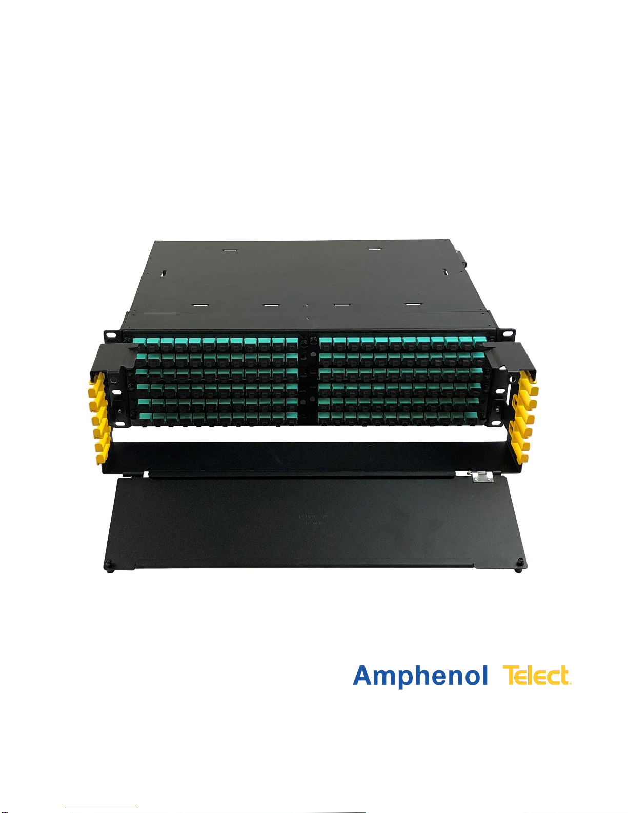
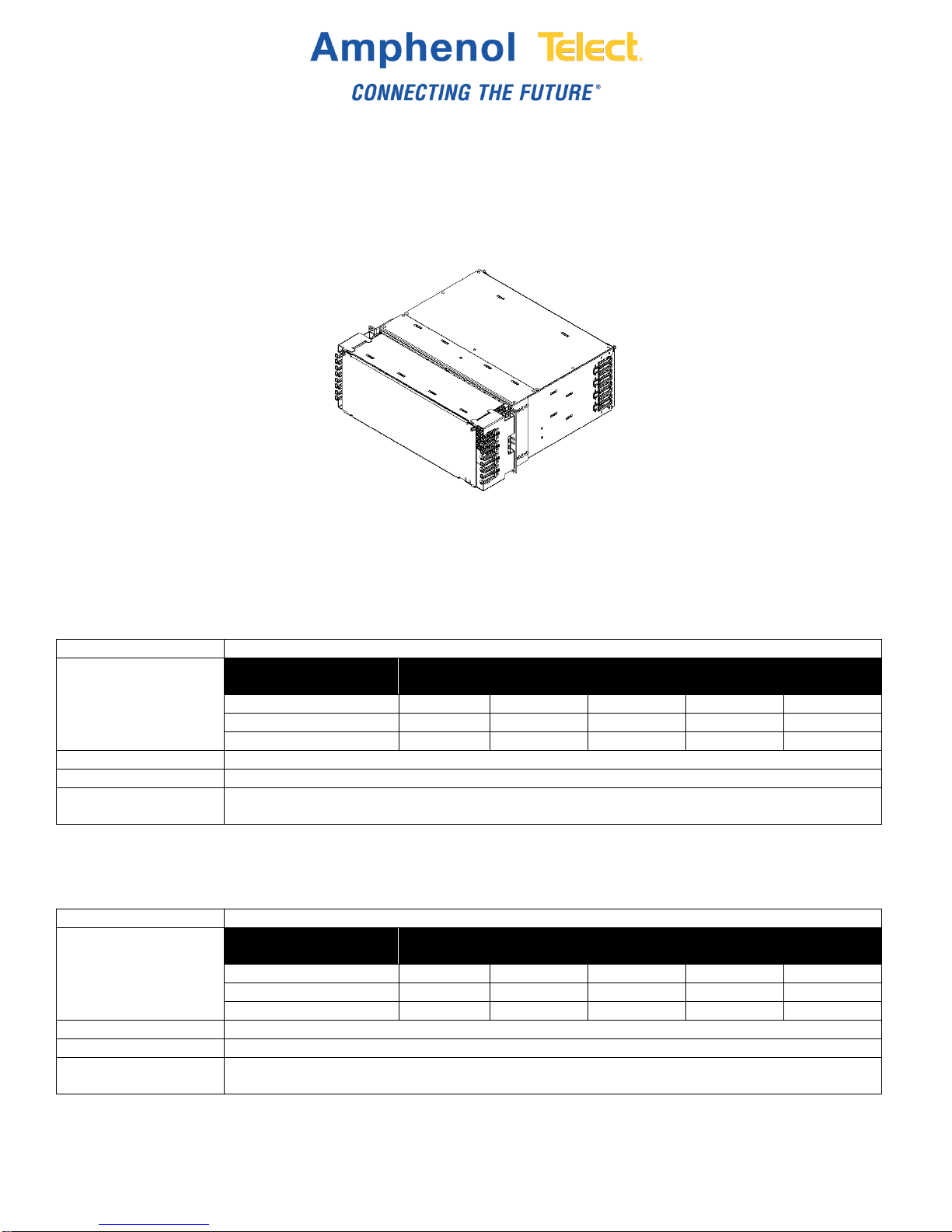
Fig. 1-1: C2X 4RU chassis ..........................................................................................................................6
Fig. 2-1: C2X tray ........................................................................................................................................9
Fig. 2-2: C2X AOM......................................................................................................................................9
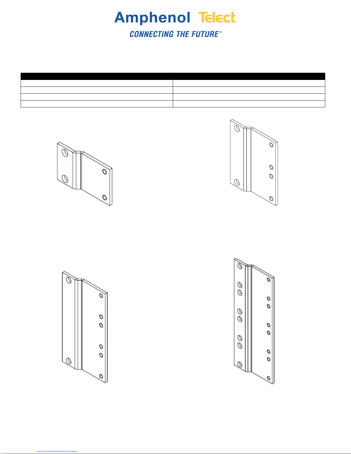
Fig. 2-3: 1RU extension bracket ................................................................................................................ 10
Fig. 2-4: 2RU extension bracket ................................................................................................................ 10
Fig. 2-5: 3RU extension bracket ................................................................................................................ 10
Fig. 2-6: 4RU extension bracket ................................................................................................................ 10
Fig. 2-7: Cable clamp ................................................................................................................................ 11
Fig. 2-8: Patch plates................................................................................................................................. 11
Fig. 2-9: Splice tray.................................................................................................................................... 12
Fig. 2-10: Cable management bezel.......................................................................................................... 12
Fig. 4-1: Open the C2X door...................................................................................................................... 15
Fig. 4-2: Opening a 1RU chassis door....................................................................................................... 15
Fig. 4-3: Front chassis positioning ............................................................................................................. 16
Fig. 4-4: Middle chassis positioning........................................................................................................... 16
Fig. 4-5: Rear chassis positioning.............................................................................................................. 16
Fig. 4-6: Mounting C2X chassis in a rack................................................................................................... 17
Fig. 4-7: Mounting the 1RU C2X chassis................................................................................................... 18
Fig. 5-1: Inserting a module into a tray....................................................................................................... 19
Fig. 5-2: Removing modules from the tray................................................................................................. 19
Fig. 6-1: Installing trays in the chassis....................................................................................................... 20
Fig. 6-2: Removing trays............................................................................................................................ 21
Fig. 7-1: Installing patch plates in the chassis............................................................................................ 22
Fig. 7-2: Removing patch plates from the chassis...................................................................................... 23
Fig. 8-1: 4RU, 3RU and 2RU designation card locations ........................................................................... 24
Fig. 8-2: 1RU designation card locations................................................................................................... 25
Fig. 9-1: Fiber cable routing....................................................................................................................... 26
Fig. 9-2: 1RU cable routing........................................................................................................................ 27
Fig. 10-1: Splice tray with cassettes........................................................................................................... 28
Fig. 11-1: Opening the splice cassette....................................................................................................... 29
Fig. 11-2: Recommended cable routing..................................................................................................... 29
Fig. 11-3: Laying out slack loops ............................................................................................................... 30
Fig. 11-4: Coiling fiber into cassette........................................................................................................... 31
Fig. 11-5: Coiling fibers under fingers........................................................................................................ 32
Fig. 11-6: Placing cover on cassette.......................................................................................................... 32
Fig. 12-1: 4RU and 3RU cable clamp ........................................................................................................ 33
Fig. 12-2: 2RU cable clamp ....................................................................................................................... 34

6
C2X
Amphenol Telect
All rights reserved. 07.10.18 149825 A0
1-509-926-6000
Section One: Introduction
This installation guide gives you directions on:
•How to install the C2X chassis on a 19-inch or 23-inch rack
•How to install C2 Advanced Optical Modules (AOMs), trays and labels
•How to route and secure the fiber optic cable
1.1 Specifications
1.1.1 C2X –4RU
Dimensions
7" H x 18.98" W x 13.75"; depth is 18.50" when front fiber management bezel is added
Optical specifications
Split Ratio (dB)
(net/mon)
50/50
60/40
70/30
80/20
90/10
LC Multimode
3.9/3.9
2.9/4.9
2.2/6.15
1.65/7.95
—
LC Single mode
3.7/3.7
2.8/2.8
2.0/6.1
1.35/8.05
0.85/12.05
MPO Multimode (SR4)
4.3/4.3
—
2.4/6.4
—
—
Chassis density
19": 4RU –16 trays –16 dual AOMs –216 SC connectors –432 LC connectors
Access
Front and rear
Mounting options
Standard 19" rack
23" rack available with optional extension brackets
1.1.2 C2X –3RU
Dimensions
5.23" H x 18.98" W x 13.75"; depth is 18.50" when front fiber management bezel is added
Optical specifications
Split Ratio (dB)
(net/mon)
50/50
60/40
70/30
80/20
90/10
LC Multimode
3.9/3.9
2.9/4.9
2.2/6.15
1.65/7.95
—
LC Single mode
3.7/3.7
2.8/2.8
2.0/6.1
1.35/8.05
0.85/12.05
MPO Multimode (SR4)
4.3/4.3
—
2.4/6.4
—
—
Chassis density
19": 3RU –12 trays –12 dual AOMs –144 SC connectors –288 LC connectors
Access
Front and rear
Mounting options
Standard 19" rack
23" rack available with optional extension brackets
Fig. 1-1: C2X 4RU chassis

7
C2X
Amphenol Telect
All rights reserved. 07.10.18 149825 A0
1-509-926-6000
1.1.3 C2X –2RU
Dimensions
3.5" H x 18.98" W x 13.75"; depth is 18.50" when front fiber management bezel is added
Optical specifications
Split Ratio (dB)
(net/mon)
50/50
60/40
70/30
80/20
90/10
LC Multimode
3.9/3.9
2.9/4.9
2.2/6.15
1.65/7.95
—
LC Single mode
3.7/3.7
2.8/2.8
2.0/6.1
1.35/8.05
0.85/12.05
MPO Multimode (SR4)
4.3/4.3
—
2.4/6.4
—
—
Chassis density
19": 2RU –8 trays –8 dual AOMs –96 SC connectors –192 LC connectors
Access
Front and rear
Mounting options
Standard 19" rack
23" rack available with optional extension brackets
1.1.4 C2X –1RU
Dimensions
1.75" H x 18.98" W x 13.75"; depth is 18.50" when front fiber management bezel is added
Optical specifications
Split Ratio (dB)
(net/mon)
50/50
60/40
70/30
80/20
90/10
LC Multimode
3.9/3.9
2.9/4.9
2.2/6.15
1.65/7.95
—
LC Single mode
3.7/3.7
2.8/2.8
2.0/6.1
1.35/8.05
0.85/12.05
MPO Multimode (SR4)
4.3/4.3
—
2.4/6.4
—
—
Chassis density
19": 1RU –4 trays –4 dual AOMs –48 SC connectors –96 LC connectors
Access
Front and rear
Mounting options
Standard 19" rack
23" rack available with optional extension brackets

8
C2X
Amphenol Telect
All rights reserved. 07.10.18 149825 A0
1-509-926-6000
1.2 About This Guide
This manual provides a comprehensive overview of and installation guidelines for the C2X chassis. While
care has been taken to define all necessary information, complete details may not be covered. If you have
any questions, contact Amphenol Telect Technical Support at [email protected]m or call 1-509-926-6000.
Throughout this guide, select information is highlighted in the form of Notes, Alerts, Cautions and Warnings.
These notifications are prominent and their importance is indicated as follows:
NOTE: General information to which the user should pay special attention.
ALERT! Important information and/or instructions to which the user should adhere.
CAUTION! Indicates a hazardous situation, which could result in minor or moderate injury.
WARNING! Indicates a potentially hazardous situation which could result in death or serious injury.
Amphenol Telect assumes no liability from the application or use of these products. Amphenol Telect does not
convey any license under its patent rights nor the patent rights of others. This document and the products
described herein are subject to change without notice.
1.3 Terminology
The following is a list of acronyms and abbreviations used throughout this manual:
Acronym/Abbreviation
Term
AOMs
Advanced Optical Modules
dB
Decibel
IFC
IntraFacility Cable
LC
Local Connector
MM
Millimeters
MPO
Multi-fiber Push On
RAL
Restricted Access Location
RU
Rack Unit
TIA
Technical Inspection Association (global product certification compliance marking)
UL
Underwriter’s Laboratories

9
C2X
Amphenol Telect
All rights reserved. 07.10.18 149825 A0
1-509-926-6000
Section Two: C2X Overview
2.1 General Description
The C2X chassis is a streamlined, dense bulkhead panel that holds Advanced Optical Modules (AOMs).
Available in 1RU, 2RU, 3RU and 4RU chassis solutions, C2X is modular solution capable of deploying any
mixture of C2 AOMs.
2.2 C2X Components
2.2.1 Trays
Universal trays for the C2X chassis slide in and out by locking and unlocking the tray plungers. This allows for
easy access to the modules. Each tray can hold two modules.
2.2.2 Advanced Optical Modules
The C2X AOMs are available in patch and splice, pre-terminated, MPO, TAPs, splitters and WDM.
Fig. 2-1: C2X tray
Fig. 2-2: C2X AOM

10
C2X
Amphenol Telect
All rights reserved. 07.10.18 149825 A0
1-509-926-6000
2.2.3 Extension Brackets
Optional extension brackets for the C2X chassis are available to install the C2X chassis in a 23" rack. All
extension brackets are sold separately. See table below for sizes and part numbers.
Bracket Size
Part Number
1RU
144049
2RU
144051
3RU
144053
4RU
145876
Fig. 2-3: 1RU extension bracket
Fig. 2-6: 4RU extension bracket
Fig. 2-4: 2RU extension bracket
Fig. 2-5: 3RU extension bracket

11
C2X
Amphenol Telect
All rights reserved. 07.10.18 149825 A0
1-509-926-6000
2.2.4 Cable Clamp
The IntraFacility Cable (IFC) clamp is a cable management clamp kit that secures IFC onto the chassis.
Chassis Size
Cable Clamp Part Number
1RU
NO CLAMP
2RU
C2X-KIT-CLMP2RU
3RU/4RU
C2X-KIT-CLMP
2.2.5 Patch Plates
Patch plates come in various sizes and configurations that fit into the C2X chassis.
Fig. 2-7: Cable clamp
Fig. 2-8: Patch plates

12
C2X
Amphenol Telect
All rights reserved. 07.10.18 149825 A0
1-509-926-6000
2.2.5 Splice Tray
The patch and splice chassis comes with a splice tray to stack splice cassettes in the rear of the chassis.
2.2.6 Front Cable Management Bezel
The removable bezel located on the front of the C2X chassis provides added fiber protection. The front bezel is
removable prior to installation. The front bezel has pre-installed cable management fingers to help route fiber in
the C2X 2RU, 3RU and 4RU chassis.
NOTE: Door left off the image below. Door comes attached with shipment.
Fig. 2-9: Splice tray
Fig. 2-10: Cable management bezel

13
C2X
Amphenol Telect
All rights reserved. 07.10.18 149825 A0
1-509-926-6000
Section Three: Installation Considerations
WARNING! Fiber cables transmit invisible infrared light. To avoid eye damage or blindness, never
look directly into fibers or connectors.
CAUTION! These instructions presume you have verified the Amphenol Telect equipment being
installed is compatible with the rest of the system including power, ground, circuit protection,
signal characteristics, equipment from other vendors, and local codes or ordinances.
ALERT! This product must be installed and maintained only by qualified technicians.
ALERT! Install this system according to company requirements. It is recommended you install the
system in a Restricted Access Location (RAL) where access is limited through the use of tool, lock
and key, or other means of security and be controlled by the authority responsible for the location.
ALERT! Prior to chassis installation, ensure there is enough space in front and rear to access
cabling.
ALERT! Only use components and crimping tools approved by agencies or certifying bodies
recognized in your country or region, such as Underwriter’s Laboratories (UL), TIA, etc.
3.1 Unpacking
Upon receipt of your order, carefully unpack contents and compare it with the packing list and the order placed.
While items described below are a comprehensive list that includes C2X chassis, trays, doors, bezel, and
splice tray, the contents of your order may vary.
3.1.1 Chassis Contents
•Installation guide
•Assembled chassis –19-inch or 23-inch
oDesignation cards
oFront bezel
oCable management ears –4RU, 3RU, 2RU
oDoors
3.1.2 Module Configurations
•All part numbers starting with C2X include trays with shipment
•All part numbers starting with HX or HX2 do not include trays with shipment, order separately
•Sold separately –C2X Tray: part number –C2X-TRAY

14
C2X
Amphenol Telect
All rights reserved. 07.10.18 149825 A0
1-509-926-6000
3.2 Inspection
Please report any defective or missing parts to Amphenol Telect Quality at quality@telect.com or call
1-509-926-6000. Keep all documentation that comes with your shipment.
Please read and understand all instructions before starting installation. If you have any questions, contact
Amphenol Telect Technical Support at support@telect.com or call 1-509-926-6000.
Exercise care when unpacking and setting the equipment in place. Amphenol Telect is not liable for transit
damage. If the product is damaged, please report it to the carrier and contact Amphenol Telect Quality at
3.3 Installation Guidelines
•Elevated Operating Ambient Temperature: If installed in a closed or multi-unit rack assembly, the
operating ambient temperature of the rack environment may be greater than room ambient. Consider
installing the equipment in an environment compatible with the maximum ambient temperature (Tma)
specified by the manufacturer.
•Mechanical Loading: Avoid uneven mechanical loading in the rack. This can cause hazardous
situations.
•Reliable Earthing: Reliable earthing of rack-mounted equipment should be maintained. Attention
should be given to supply connections other than direct connections to the branch circuit (e.g., use of
power strips).
3.4 Location and Space
C2X chassis, trays and modules require enough space in front and rear for easy access. Leave as much side
clearance for tray and chassis removal and worker access as required by your application or local regulations.
Choose a location in compliance with local operating company requirements.
3.5 Tools and Equipment
The following lists comprises the tools that may be needed to install and maintain the C2X chassis, trays and
modules:
•Phillips head screwdriver with 6" extension

15
C2X
Amphenol Telect
All rights reserved. 07.10.18 149825 A0
1-509-926-6000
Section Four: C2X Installation Instructions
4.1 Opening the C2X Doors
The following installation instructions refer to the 4RU, 3RU and 2RU chassis sizes.
1. Locate the locking pins on the left and right side of the front door.
2. Pull the locking pins out of the locked position to release the door.
3. Pivot door down on the hinges to open.
The following installation instructions refer to the C2X 1RU chassis only.
1. Locate the latch on the left and right side of the front door.
2. Push down on both latches to release the top of the door.
3. Pivot door on the hinges to open.
Fig. 4-2: Opening a 1RU chassis door
Fig. 4-1: Open the C2X door

16
C2X
Amphenol Telect
All rights reserved. 07.10.18 149825 A0
1-509-926-6000
4.2 Mounting the C2X Chassis on the Rack
The following installation instructions refer to the 4RU, 3RU and 2RU chassis sizes.
1. Locate the desired rack space for the C2X chassis.
2. Determine the chassis positioning that fits your application.
NOTE: The chassis has three positioning options. See table below.
Connector Length
Chassis Positioning
Mini boot
Front positioning
Standard boot (Default)
Middle positioning
Long boot/Attenuators
Rear position
Fig. 4-3: Front chassis positioning
Fig. 4-4: Middle chassis positioning
Fig. 4-5: Rear chassis positioning

17
C2X
Amphenol Telect
All rights reserved. 07.10.18 149825 A0
1-509-926-6000
3. Open the front door to access the C2X chassis mounting brackets.
4. Using a Phillips screwdriver with 6" extension and the provided Phillips screws, install the chassis on the
front of the rack by aligning the mounting holes on the bracket with the holes on the rack. Use two screws
per side to attach the chassis to the rack.
Fig. 4-6: Mounting C2X chassis in a rack

18
C2X
Amphenol Telect
All rights reserved. 07.10.18 149825 A0
1-509-926-6000
The following installation instructions refer to the 1RU C2X chassis only.
1. Locate the desired rack space for the C2X chassis.
2. Open the front door to access the C2X chassis mounting brackets.
3. Using a Phillips screwdriver and the provided Phillips screws, install the chassis on the front of the rack by
aligning the mounting holes on the bracket with the holes on the rack. Use two screws per side to attach
the chassis to the rack.
4.3 Extension Brackets
Extension brackets for the C2X chassis are available (sold separately) to fit in a 23" rack.
When mounting to a 23" rack, follow these instructions to mount the brackets:
1. Attach both extension brackets to each side of the C2X chassis mounting holes using the Phillips screws
provided in the bracket kit.
2. Once both brackets are installed, locate the desired rack space for the C2X chassis.
3. Using a Phillips screwdriver and the provided Phillips screws, install the chassis on the front of the rack by
aligning the extension bracket mounting holes with the holes on the rack. Use two screws per side to attach
the chassis to the rack.
Fig. 4-7: Mounting the 1RU C2X chassis

19
C2X
Amphenol Telect
All rights reserved. 07.10.18 149825 A0
1-509-926-6000
Section Five: Installing and Removing Modules
5.1 Installing Modules in a Tray
The following installation instructions refer to all C2X and HX AOMs.
1. Determine which side of the module will be the front and rear.
2. Insert the module into the desired space on the tray. Slightly angle the front of the module down and slide it
forward until connectors are sticking out of the tray.
3. Line up tabs on the side of the module with the tab openings on the tray.
4. Press down until tabs lock together.
5.2 Removing Modules from the Tray
The following installation instructions refer to all C2X and HX AOMs.
1. Push up on the module to unlock the tabs from the tray.
2. Pull module out and away from tray.
Tabs
Fig. 5-1: Inserting a module into a tray
Push up on module
Pull out of tray
Insert module and slide forward
Fig. 5-2: Removing modules from the tray

20
C2X
Amphenol Telect
All rights reserved. 07.10.18 149825 A0
1-509-926-6000
Section Six: Installing and Removing Trays in the Chassis
6.1 Installing Trays into the Chassis
When installing trays in the C2X chassis, start at the bottom-most tray position and work your way up as you
add in trays.
The following installation instructions refer to all C2X chassis sizes.
1. Open front door of chassis to access space for trays and modules.
2. Before installing trays, make sure the tray plungers on the sides of the tray are in the unlocked position. If
they are not, pull plungers out to unlock them.
3. Slide bottom of tray over the small metal support bar inside the chassis.
4. Align pins with the chassis pin holes on the support bars.
5. Push tray into chassis until the tray faceplate is flush with the support bars and the plungers are inserted
into the plunger holes.
6. Push in plungers until they snap into the locked position.
7. Repeat steps 1-6 for all remaining trays.
Fig. 6-1: Installing trays in the chassis
Table of contents
Popular Home Automation manuals by other brands

F&G
F&G Moeller Xcomfort CJAU-01/02 Assembly instructions

Honeywell Home
Honeywell Home Evohome installation guide

HomeSeer Technologies
HomeSeer Technologies HomeTroller SE Edition Getting started guide

Partizan
Partizan Myers MSP-1EU user manual

Hama
Hama 00176552 operating instructions

Toshiba
Toshiba Symbio manual