Amplicon Magic 485F25 User manual

Magic 485F Adapter
Amplicon products are produced in the United Kingdom under a quality system
approved by the British Standards Institution
Magic 485F25 & F9
RS 232-485
AUTOMATIC
RS 485
TRANSMITTER
ENABLE
This Instruction Manual is supplied with the Magic 485F Adapter to provide the user with sufficient information to
utilise the purchased product in a proper and efficient manner. The information contained has been reviewed and is
believed to be accurate and reliable, however Amplicon Liveline Limited accepts no responsibility for any
problems caused by errors or omissions. Specifications and instructions are subject to change without notice.
Magic 485F Instruction Manual Part Nº 859 933 74 Issue A3
© Amplicon Liveline Limited
Prepared by James Chisholm
Approved for issue by A.S. Gorbold, Operations Director
BS EN ISO 9001
Certificate No. FM 15094 Affirmed by
Declaration of Conformity

Magic 485F Adapter
DECLARATION OF CONFORMITY
AMPLICON LIVELINE LIMITED
CENTENARY INDUSTRIAL ESTATE
HOLLINGDEAN ROAD
BRIGHTON BN2 4AW UK
We declare that the product(s) described in this Instruction Manual
perform in conformity with the following standards or standardisation
documents:
Electro Magnetic Compatibility (EMC):
EN55022:1995 Emission Standard
BS EN50082-1:1992 Generic Immunity Standard
EMC Directive 89/336/EMC
Jim Hicks, I. Eng, FIEIE
Managing Director
Amplicon Liveline Limited

Magic 485F Adapter Page 1
MAGIC 485F
1INTRODUCTION
1.1 General Description
The Magic 485F ‘MAGIC converter’ transfers data between RS232 & RS485 networks. The unit
is ‘magic’ in that, unlike conventional converters, it does not require the RTS signal to control
RS485 transmitter turnaround. Instead the RS485 transmitter is enabled whenever a valid start
bit is detected on the RS232 input. This feature can be very useful when connecting RS232
based modems, or other systems that do not support RTS handshaking to RS485 multidrop
networks.
The data conversion process changes only electrical levels and the pin-out configuration is in
accordance with the appropriate standards. As default the unit is supplied for the RS232 host
device configured as Data Terminal Equipment (DTE) but can be changed by jumpers to a Data
Communication Equipment (DCE).
RS485 multi-drop operation allows up to 32 devices to be connected in a simple network on a
single serial bus. The transmitter has a tri-state output and is automatically disabled to allow
reception over the same wire pair.
DC power for the Magic 485F Adapter must be applied from an external source. The DC power
lines plus the RS422/485 data and control signals are connected through a pluggable 8 way
screw terminal assembly at the free end of the Adapter.
1.2 The Products Described in this Manual
The 485F range of boards share some common circuitry and features and are referred to in this
manual either generically or individually:
485F Refers to both boards
485F25 Refers to the 25 way D-type version only
485F9 Refers to the 9 way D-type version only
1.3 Circuit Operation
The Magic 485F Adapter converts the electrical levels of signals from those specified for RS232
to the RS422/485 levels and vice versa. This conversion is done via intermediate TTL levels.
RS232 <–––> TTL
U2 is a MAX2322E (or equivalent) 5 V powered CMOS RS232 Driver/Receiver. A DC-DC
converter is built into the chip to provide a typical ±9 V output swing of the RS232 lines.
This receiver accepts signal at RS232 levels and converts these signals to TTL levels for
internal use. The first receiver accepts the transmitted data (TxD) signal from the RS232 port
and translates it to TTL levels for onward conversion by the RS422/485 driver.
This line is then fed to a FPGA device, U4, which monitors the data coming into the unit. If
the unit detects a valid start bit, the device enables the transmitter and disables the
receiver of the MAX491 transceiver chip U1. Once the packet of data is transmitted and
the turnaround time has passed, as set by SW1, the unit reverts to receive mode.

Page 2Magic 485F Adapter
RS422 / 485 <–––> TTL
Conversion between the differential signal levels of RS422/485 and the internal TTL levels is
performed by the MAX491 (or equivalent) transmitter and receiver U1. In normal operation the
unit is in receive mode and data is transferred directly to the RS232 port.
When the unit transmits data it is enabled by the FPGA and data flows out on to the RS485 bus.
The unit is configured to echo data back to the receive port, however this can be disabled during
transmission by the setting of Jumper J3.
DTR, DSR and DCD
The RS232 port DSR and DCD inputs are linked to the DTR output to ensure that the RS232
operation does not lock up awaiting a handshake signal.
Power Regulator
Q1 is a low dropout +5 volt regulator to supply the Magic 485F Adapter circuits. The limits of the
input voltage to this regulator are >+5.0 VDC and <+12.0 VDC. Over this range, the output is
between +4.8 and +5.2 VDC.
1.4 Technical Support
Should the Magic 485F Adapter appear defective, please check the information in this manual to
ensure that the product is being correctly applied.
If an application problem persists, please request Technical Support on one of the following
numbers:
Telephone: UK 01273 608 331
International +44 1273 608 331
Fax: UK 01273 570 215
International +44 1273 570 215
Internet www.amplicon.co.uk
1.5 Repairs
If the Magic 485F Adapter requires repair then please return the goods enclosing a repair order
detailing the nature of the fault. If the product is still under warranty, which is for a period of 12
months from the date of shipment, there will be no repair charge unless the fault has been
caused by misuse.
For traceability when processing returned goods, a Returned Materials Authorisation (RMA)
procedure is in operation. Before returning the goods, please request an individual RMA number
by contacting Amplicon Technical Support by telephone or fax on the above numbers.
Give the reason for the return and, if the goods are still under warranty, the original invoice
number and date. Repair turnaround time is normally five working days but the Service
Engineers will always try to co-operate if there is a particular problem of time pressure.

Magic 485F Adapter Page 3
Please mark the RMA number on the outside of the packaging to ensure that the package is
accepted by the Goods Inwards Department.
Address repairs to: Customer Services Department
AMPLICON LIVELINE LIMITED
Centenary Industrial Estate
Brighton, East Sussex
BN2 4AW
England

Page 4Magic 485F Adapter
2INSTALLATION INSTRUCTIONS
2.1 Requirements of Host Equipment
The Magic 485F25 Adapter can be plugged into any device with an RS232 port terminating in a
25 way 'D' type male connector (DB-25). If the host device is equipped with a 25 way connector,
it is normally male, and the Magic 485F25 Adapter can be directly plugged into this port.
The 485F9 Adapter can be plugged into any device with an RS232 port terminating in a 9 way 'D'
type male connector (DB-9).
2.2 Connections to the Magic 485F Adapter
Connections are made to the Magic 485F Adapter at each end. The RS232 connections are
automatically made when the Adapter is plugged into the port, and the RS422/485 data, control
and power connections must be made through a pluggable 8 way screw terminal connector
assembly at the free end.
RS422/485 Connections on 8 way Pluggable Terminal Strip
The DC power input, RS485 transmission turnaround external control signal and RS422/485
data signal connections are made via an eight way screw terminal connector. The supplied
connector can be unplugged from the Adapter for ease of making the cables without removing
the Adapter from the port.
The connections are compatible with other RS485 Adapters in the Amplicon range, and are
shown in Figure 2.2 below. The diagram shows the connector as viewed from the top face of the
Magic 485F Adapter. The abbreviated function names are printed on the printed circuit board
below the fixed part of the connector.
FIGURE 2.2 RS422/485 CONNECTIONS
1GND Ground
2NC
3BTransmit Data
4A/Transmit Data
5A’ /Receive Data
6B’ Receive Data
7VDC +5.0 to +12 VDC
8GND Power Ground
RS422/485 power, data and control connections

Magic 485F Adapter Page 5
2.3 Configuration of Magic 485F Adapter Options
Configuration of the options is undertaken by the setting of links and switches on the baseboard.
For convenience, the plastic case is supplied in two parts and should only be clipped together
when any configuration changes have been made. Operational tests can be performed before
the case is fitted.
FIGURE 2.1485F25 BOARD LAYOUT AND JUMPER POSITIONS
FIGURE 2.2485F9 BOARD LAYOUT AND LINK POSITIONS
SK2
PL1
J2
C2
U1
C3
U4
U5
C6
R5
C2
U3
C1
R6
J3
C7
R4
R3
R2
C5
C4
R1
D1
J1

Page 6Magic 485F Adapter
2.4 Configurable Options
Selection of DCE or DTE (485F25 only)
The unit, as supplied from the factory, is configured to interface directly to a DTE i.e. a PC or
dumb terminal . In the majority of applications this will be correct. This is set by the Jumpers J1
to J2. If required the unit can be converted to connect to a DCE e.g. a moedm, by the
repositioning of J1 and J2, as detailed below.
Link Function
J1 1-2 & J2 1-2 RS232 connector wired as PC serial port (default factory setting)
J1,1- J2,1 & J1,2 - J2,2 RS232 connector wired as Modem serial port
Selection of Local Echo On/Off in Half Duplex Operation
The factory default configuration of link (J3) fitted causes the transmitted data to be echoed to
the receiver in half duplex operation. If this echo is not required, the link can be removed.
For full duplex operation, the link J3 must be in its default condition for the receiver to be
continuously enabled. Echo back is not appropriate to full duplex operation.
Link
485F25 485F9 Function
J3 1-2 J3 linked RS485 local echo disabled (default factory setting)
J3 2-3 J3 cut RS485 local echo enabled, transmitted character echoed back to
receiver
Transmission Line Termination
For proper operation of the RS422/485 bus in full or half duplex, multi-drop or point-to-point
communication, it is recommended that termination be applied to the receiver end of the data
lines. The simplest form of termination is line-to-line with typically a 120 Ωresistor across the
differential input.
In a multi-drop system, the terminator resistor is only required at the device receiver located at
the far end of the cable. If this is in half duplex operation, then both ends of the bus cable are
equipped with receivers (transceivers) so termination is necessary at both ends. Although the
Magic 485F Adapter will drive loads as low as 27 Ω, in general, RS485 transmitter circuits are
specified as being capable of driving a minimum load resistance of 60 Ω, so no more than two
terminator resistors should be connected to any one bus.
The Magic 485F Adapter is equipped with a terminator resistor for the receiver input pair. This
resistor is connected into circuit by the setting of switch SW1 Bit 4 on the 485F25 or solder link
J1 on the 485F9. Factory default settings are with the receiver input termination in circuit (SW1-
4, on) for the 485F25, and (J1 solder link tracked) for the 485F9. It can be removed from the
circuit by setting SW1-4 to off on the 485F25 or cutting the fine track connecting the pads of J1
on the 485F9.

Magic 485F Adapter Page 7
2.5 Transmitter Turnaround Delay
By the nature of the operation of the unit there will be a time delay in the switching of the unit from
transmit to receive. This time can be fine tuned to the particular installation and the length of the cable
run, resulting in quicker operation. This operation can only be tested on a trial basis and is
accomplished by the setting of SW1 Bits 1-3 on the 485F25 as described in Table 2.1, and cutting or
resoldering the tracks between the pads of J2 on the 485F9 as shown in
Figure 2.3.
1 2 3 4 Function
X X X ON RS485 termination on, termination resistor fitted
X X X OFF RS485 termination off, termination resistor not fitted
OFF OFF OFF XRS485 transmitter turnaround time = 4 us.
ON OFF OFF XRS485 transmitter turnaround time = 8 us.
OFF ON OFF XRS485 transmitter turnaround time = 16 us.
ON ON OFF XRS485 transmitter turnaround time = 32 us.
OFF OFF ON XRS485 transmitter turnaround time = 64 us.
ON OFF ON XRS485 transmitter turnaround time = 128 us.
OFF ON ON XRS485 transmitter turnaround time = 256 us.
ON ON ON XRS485 transmitter turnaround time = 512 us. (default)
TABLE 2.1485F25 BIT SWITCH SETTINGS AND FUNCTION
FIGURE 2.3485F9 LINK SETTINGS AND FUNCTION
RS485 transmitter
turnaround time = 4us
RS485 transmitter
Turnaround time = 8us
RS485 transmitter
Turnaround time = 16us
RS485 transmitter
Turnaround time = 32us
RS485 transmitter
turnaround time = 64us
RS485 transmitter
Turnaround time = 128us
RS485 transmitter
Turnaround time = 256us
RS485 transmitter
Turnaround time = 512us
(default)
R4
R3
R2
Position of links on 485F9

Page 8Magic 485F Adapter
2.6 Power Requirements
The Magic 485F Adapter must be powered from an external power supply providing a positive
output of between +5.0 VDC and +12.0 VDC. This auxiliary power supply unit should be capable
of sourcing at least 100 mA for each 485 Adapter that it supplies. Within this constraint, as many
485 Adapters as are required can be fed from a single supply. The Amplicon Mains adapter
meets this requirement and the U.K. version is available under order code 919 135 69. See
paragraph 2.4.1 for information on connecting this mains adapter to the Magic 485F terminals.
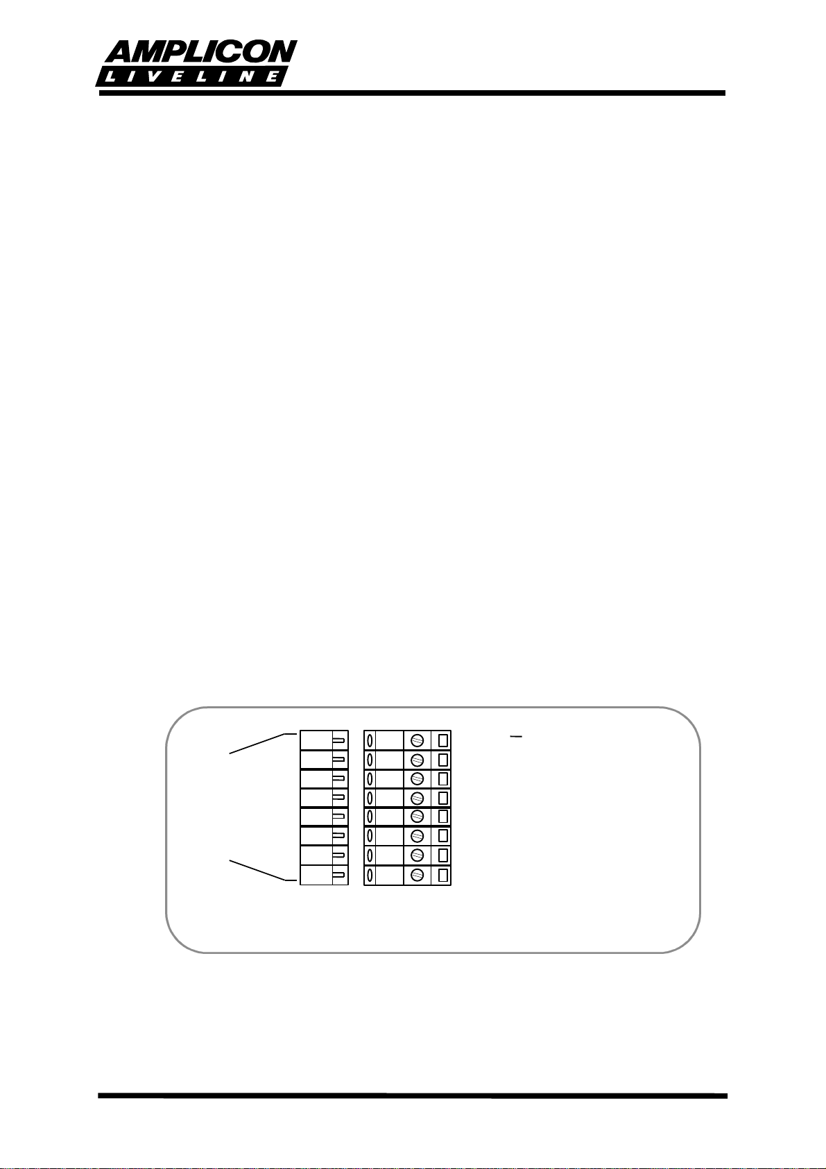
The Magic 485F Adapter is fitted with an eight way pluggable terminal strip at its free end, and
the power supply should be connected to terminals 7 and 8. Terminal 8 is Ground or negative,
terminal 7 is the positive supply. OBSERVE POLARITY when powering the adapter. If the
polarity is incorrect, the Magic 485F Adapter will not operate, but is protected against damage.
2.7 Connecting the Amplicon Mains Adapter
The optional mains adapter plugs directly into a 3 pin, 13 A mains socket (U.K. version), or must
be fitted with a suitable plug (International version). The mains supply voltage must be 230 VAC
±10%, 50 Hz. The DC output is by a two-wire cable approximately 2 m in length. This cable is
terminated in a moulded connector which must be cut off and discarded. The two wires can then
be parted and stripped back about 6 mm. The black wire is negative and goes to terminal 8
(GND) of the Magic 485F Adapter, and the black wire with a white stripe is positive and goes to
terminal 7 (VDC). Section 2.8 gives the Amplicon order codes for the above adapters.
2.8 Optional Accessories
U.K. Mains Adapter Power Supply
Amplicon Description Function
Order Code
919 135 69 Plug-in mains Provides +9 VDC at 200 mA to power one or two Magic
Adapter 485F Adapters. Mains operated 230/240 VAC. Integral 3
pin, 13 A, UK style plug. Two wire output cable of 2 m
length. Moulded connector to be removed for screw
terminal connection to Magic 485F Adapter. Wire with
white stripe is positive.
The U.K. Mains Adapter complies with the requirements
of British Standard BS415
International Mains Adapter Power Supply
919 448 69 Wired-in mains Provides +9 VDC at 200 mA to power one or two Magic
Adapter 485F Adapters. Mains operated 220/230 VAC. Two wire
(Brown - live, blue - neutral), 1.5 m length mains input
cable. Two wire output cable of 2 m length. Moulded
power connector to be removed for screw terminal
connection to Magic 485F Adapter. Wire with white
stripe is positive.

Magic 485F Adapter Page 9
3TECHNICAL SPECIFICATION
The technical characteristics of the Magic 485F Adapter are in accordance with the following
electrical and physical specifications.
Except where otherwise noted, all specifications are typical at 25º C
Electrical Specification
Supply Voltage +5.0 VDC to +12.0 VDC
from external supply via terminal strip
Supply Current 50 mA plus current drawn by output loads
100 mA fully loaded
RS232 'High' signal input +2.4 to +30 V
RS232 'Low' signal input –30 to +0.8 V
RS232 Input Resistance 5 kΩ
RS232 'High' signal output +9 V
RS232 'Low' signal output –9 V
RS232 Output Resistance 300 Ω
RS422/485 Input sensitivity 0.2 V
RS422/485 Input Hysteresis 70 mV
RS422/485 Output drive 1.5 V minimum, fully loaded
RS422/485 Output load 27 Ωminimum
RS422/485 Receiver I/P Termination 120 Ωresistor across differential input terminals.
Can be disconnected by switching SW1-4
Data Rate 120 kBd max
RS232 Connector 25 way DB-25 female connector with screw-locks
RS422/485 Connector 8 way pluggable screw terminal assembly
Physical/Environmental Specification
Module with connector Packed
Size 67 x 53 x 20 mm 215 x180 x 80 mm
Weight 60 gm 250 gm
Temperature Range Operating Storage
0° C to +60° C -20 to +70° C
This manual suits for next models
1
Table of contents