User Manual of W20-GSM Indoor single band selective repeaters
Confidential Page 1
CATALOGUE
CHAPTER 1. SAFETY WARNNING................................................................................2
CHAPTER 2. SUMMARY ................................................................................................3
CHAPTER 3. SPECS AND FEATURES..........................................................................4
3.1 F
EATURES
...............................................................................................................................4
3.2 S
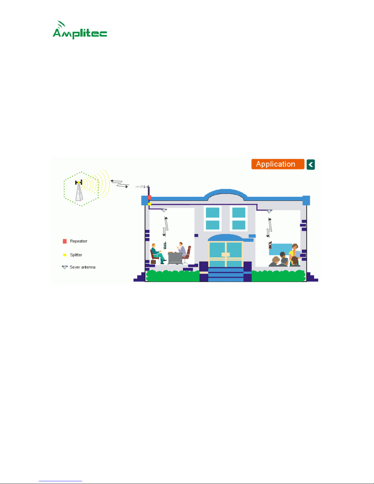
YSTEM DIAGRAM
....................................................................................................................4
3.3 E
LECTRICAL
S
PECIFICATION
.....................................................................................................4
3.4 M
ECHANICAL
S
PECIFICATION
....................................................................................................4
3.5 A
PPEARANCE
D
IAGRAM
...........................................................................................................6
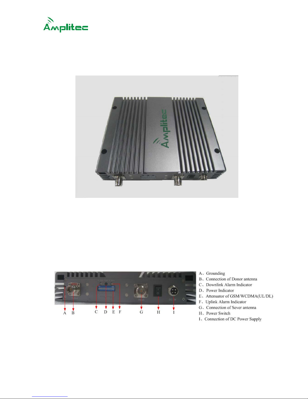
3.6 P
ORTS
.....................................................................................................................................6
CHAPTER 4. INSTALLATION.........................................................................................7
4.1
I
NSTALLATION REQUIREMENTS
.......................................................................................................7
4.2
I
NSTALLATION
...............................................................................................................................7
4.3
C
ONNECTION
................................................................................................................................9
4.4
S
YSTEM INSPECTION
...................................................................................................................10
CHAPTER 5. REPEATER SETTING.............................................................................10
5.1
P
OWER SUPPLY CONNECTION
......................................................................................................10
5.2
P
ERFORMANCE
S
ETTING
.............................................................................................................11
CHAPTER 6. ENGINEERING MAINTENANCE ............................................................13
6.1
O
PERATION AND MAINTENANCE
...................................................................................................13
6.2
E
MERGENCY DEALING
.................................................................................................................13
6.3
M
AINTAINING DIRECTIONS
............................................................................................................14