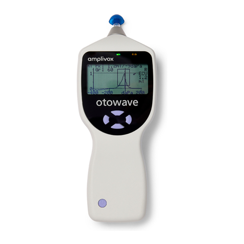
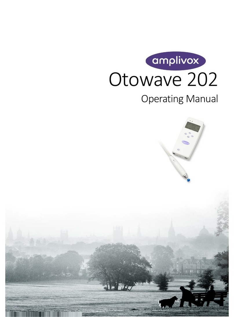
AmpliVox Otowave 202 User manual

Otowave 202
Operating Manual

ABOUT THIS MANUAL
READ THIS OPERATING MANUAL BEFORE ATTEMPTING TO USE THE INSTRUMENT.
This manual is valid for the Otowave 202 (applies to firmware version 1.0.0.072200).
This product is manufactured by:
Amplivox Ltd.
6 Oasis Park, Eynsham
Oxfordshire, OX29 4TP
United Kingdom
www.amplivox.ltd.uk
Amplivox Ltd.
10393 West 70th Street
Eden Prairie
MN 55344
www.amplivox.us
For all enquiries please contact us under:
Tel: 888 941 4208
Fax: 952 903 4100
info@amplivox.us

For supply in US only
Caution: Federal Law restricts this device to sale by or on the order of a licenced medical professional.
Indications for Use
The Otowave 202 Portable Tympanometer is designed for use by trained operators (audiologists, general
practitioners, hearing aid dispensers, and child health professionals) in hospitals, ENT clinics, and audiologist offices
for the detection of possible otologic disorders in the general population associated with the functioning of the middle
ear.
The instrument performs two types of measurement:
Tympanometry is used to measure the acoustic admittance (which is also known as “compliance”) of the tympanic
membrane and middle ear at a fixed frequency over a range of pressures.
Reflex tests are used to measure stapedial reflexes. The Otowave 202 measures ipsilateral reflexes and, when
selected, reflex measurement is automatically carried out after a tympanogram is taken.
Release date: June 21st 2017

i
D-0115692-C (OM031) –Otowave 202 Operating Manual
TABLE OF CONTENTS
1. INTRODUCTION........................................................................................................................................................... 1
1.1. THANK YOU ...................................................................................................................................................................1
1.2. INTENDED APPLICATIONS..............................................................................................................................................1
1.3. FEATURES ......................................................................................................................................................................1
1.4. UNPACKING ...................................................................................................................................................................1
1.5. STANDARD CONTENTS AND OPTIONAL ACCESSORIES..................................................................................................2
1.6. WARNINGS ....................................................................................................................................................................2
1.7. WARRANTY CARD (UK CUSTOMERS ONLY) ...................................................................................................................2
1.8. GUARANTEE...................................................................................................................................................................2
2. IMPORTANT SAFETY INSTRUCTIONS ........................................................................................................................... 4
2.1. PRECAUTIONS................................................................................................................................................................4
2.2. ELECTROMAGNETIC COMPATIBILITY (EMC) CONSIDERATIONS ....................................................................................4
2.3. POWER SUPPLY OPTIONS..............................................................................................................................................5
2.4. TYMPANOMETER CONNECTIONS..................................................................................................................................5
2.5. DATA TRANSFER TO A PRINTER.....................................................................................................................................6
2.6. DATA TRANSFER TO A COMPUTER................................................................................................................................6
3. PRINCIPLES OF OPERATION......................................................................................................................................... 7
3.1. OTOSCOPIC EXAMINATION ...........................................................................................................................................7
3.2. PRINCIPALS OF ADMITTANCE MEASUREMENT .............................................................................................................7
3.3. TYMPANOGRAM............................................................................................................................................................7
3.4. ACOUSTIC REFLEX MEASUREMENT ...............................................................................................................................8
4. USING THE OTOWAVE................................................................................................................................................. 9
4.1. INSTALLING & REPLACING BATTERIES...........................................................................................................................9
4.2. OPERATING LANGUAGE ................................................................................................................................................9
4.3. CONTROLS AND INDICATORS (BASE UNIT)..................................................................................................................10
4.4. INDICATORS AND SYSTEM STATUS..............................................................................................................................10
4.5. THE PROBE...................................................................................................................................................................11
4.5.1. Controls and indicators (probe).......................................................................................................................11
4.5.2. The Probe Head..............................................................................................................................................11
4.6. CONTRALATERAL TRANSDUCER ..................................................................................................................................12
4.7. START-UP AND MENU DISPLAYS .................................................................................................................................12
4.8. INITIAL SETTINGS.........................................................................................................................................................12
5. TAKING MEASUREMENTS.......................................................................................................................................... 13
5.1. PRIOR TO TESTING AND AMBIENT CONDITIONS.........................................................................................................13
5.2. EAR TIP(S) ....................................................................................................................................................................13
5.3. PERFORMING A TEST...................................................................................................................................................14
6. CONFIGURATIONS..................................................................................................................................................... 19
6.1. SWEEP SETTINGS .........................................................................................................................................................19
6.1.1. Scalar Mode –226 Hz.....................................................................................................................................19
6.1.2. Scalar and vector Mode –1000 Hz.................................................................................................................20
6.1.3. Selecting alternative display modes................................................................................................................21
6.1.4. Ear seal check.................................................................................................................................................21
6.2. REFLEX OPTIONS..........................................................................................................................................................22
6.3. SYSTEM SETTINGS .......................................................................................................................................................23
7. SAVING RESULTS IN THE INTERNAL DATABASE ......................................................................................................... 25
7.1. DATA ENTRY ................................................................................................................................................................25
7.2. DATABASE FULL...........................................................................................................................................................25

ii
D-0115692-C (OM031) –Otowave 202 Operating Manual
8. SENDING THE RESULTS TO A PRINTER ....................................................................................................................... 26
9. DATA TRANSFER TO NOAH OR AMPLISUITE .............................................................................................................. 28
10. DATA MANAGEMENT................................................................................................................................................ 29
10.1. LIST RECORDS ..............................................................................................................................................................29
10.2. DELETE RECORDS.........................................................................................................................................................30
10.3. PRINT RECORDS...........................................................................................................................................................30
10.4. CONNECT VIA USB .......................................................................................................................................................30
11. PERFORMING DAILY CHECKS..................................................................................................................................... 31
12. SYSTEM INFORMATION............................................................................................................................................. 32
13. ROUTINE MAINTENANCE .......................................................................................................................................... 33
13.1. CLEANING THE OTOWAVE...........................................................................................................................................33
13.2. EARTIPS AND PROBE ...................................................................................................................................................33
13.3. CALIBRATION AND RETURN OF THE INSTRUMENT .....................................................................................................33
14. ERROR MESSAGES & FAULT CONDITIONS ................................................................................................................. 35
15. TECHNICAL SPECIFICATION........................................................................................................................................ 38
15.1. PERFORMANCE............................................................................................................................................................38
15.2. EQUIPMENT CLASSIFICATION......................................................................................................................................40
15.3. SYMBOLS .....................................................................................................................................................................40
16. ORDERING CONSUMABLES AND ACCESSORIES.......................................................................................................... 41
17. DISPOSAL INFORMATION.......................................................................................................................................... 42
18. EMC GUIDANCE & MANUFACTURER’S DECLARATION ............................................................................................... 43
19. USE WITH NON-MEDICAL ELECTRICAL EQUIPMENT................................................................................................... 47
20. 1000HZ TYMPANOMETRY AND MEATUS COMPENSATION........................................................................................ 51
20.1. TYMPANOMETRIC PROPERTIES...................................................................................................................................51
20.2. TYMPANOMETRIC MEASUREMENTS...........................................................................................................................51
20.3. ADDITIONAL POINTS TO CONSIDER.............................................................................................................................52

INTRODUCTION
1
D-0115692-C (OM031) –Otowave 202 Operating Manual
1. INTRODUCTION
1.1.THANK YOU
Thank you for purchasing the Amplivox Otowave 202, a portable tympanometer incorporating an
ergonomically-designed remote probe assembly that will give many years of reliable service if treated with
care.
This operating manual applies to the Otowave 202 which is available as a standard option (with 226Hz probe
tone) and as an H-option (with 226Hz and 1000Hz probe tones). Text that applies to 1000Hz operation only is
marked H.
1.2.INTENDED APPLICATIONS
The Otowave 202 is designed for use by audiologists, general practitioners, hearing aid dispensers and child
health professionals.
The instrument performs two types of measurement:
Tympanometry is used to measure the acoustic admittance (which is also known as “compliance”) of the
tympanic membrane and middle ear at a fixed frequency over a range of pressures.
Reflex tests are used to measure stapedial reflexes. When selected, reflex measurement is automatically
carried out after a tympanogram is taken.
1.3.FEATURES
Automatic measurement of ear canal volume, tympanic admittance peak and placement of the peak
using either 226Hz or 1000Hz Hprobe tone with various display options for the tympanometric data
Automatic detection of stapedial reflexes using a choice of ipsilateral and/or contralateral reflex
stimulus
Choice of frequency and level for reflex stimulus
Up to 18, dual-ear patient tests can be stored in non-volatile memory
An intuitive menu system for operation, setting test options and other user preferences, held in non-
volatile memory
Printout via an infrared (IrDA) link to one of two thermal printers that may be selected by the user
Data transfer to computer via a USB connection for storage, viewing & printing using either the
Amplivox “ampliSuite” software or the NOAH application
English, German, French, Spanish, Portuguese or Italian operating language (selectable by the user)
1.4.UNPACKING
Please check the contents of the shipping carton against the delivery note to make sure that all items ordered
have been included. If anything is missing, please contact the distributor who supplied the tympanometer or
Amplivox if purchased directly.
Please retain the original shipping carton and packaging to transport the tympanometer for annual calibration
or repair.

INTRODUCTION
2
D-0115692-C (OM031) –Otowave 202 Operating Manual
1.5.STANDARD CONTENTS AND OPTIONAL ACCESSORIES
STANDARD COMPONENTS
Otowave 202 Tympanometer
Set of disposable ear-tips
T20
CD with Software (ampliSuite and
Noah impedance module) and
Operating Manuals
4 in 1 cavity assembly
(0.2 ml/0.5 ml/2.0 ml/5.0 ml)
4 x 1.5V Alkaline ‘AA’ Batteries
Carrying case
Mains adapter
Calibration certificate
Contralateral transducer
Warranty card
OPTIONAL COMPONENTS
Additional sets of ear tips
T20
Probe tip
80025921
Portable thermal printer
Seal (in probe tip)
80020091
Additional rolls of thermal printer
paper
USB Cable
F07
Note: If the thermal printer has been purchased it should be charged for a minimum of 15 hours before being
used. Refer to the printer instructions for further details.
1.6.WARNINGS
Throughout this manual, the following meanings of warnings and cautions apply:
The WARNING label identifies conditions or practices that may present danger to the
patient and/or user.
The CAUTION label identifies conditions or practices that could result in damage to the
equipment.
1.7.WARRANTY CARD (UK CUSTOMERS ONLY)
Please complete the enclosed warranty registration card and return it to Amplivox. This will enable us to
register your purchase, help with your enquiries and provide technical support.
1.8.GUARANTEE
All Amplivox instruments are guaranteed against faulty materials and manufacture. The instrument will be
repaired free of charge for a period of two years from the date of dispatch if returned, carriage paid, to the
Amplivox service department. Return carriage is free of charge for customers in the UK and chargeable for
overseas customers.
1
Applied part as according to IEC 60601-1
WARNING
CAUTION

INTRODUCTION
3
D-0115692-C (OM031) –Otowave 202 Operating Manual
The following exceptions apply:
The pressure pump and transducers may go out of calibration due to rough
handling or impact (dropping).
The lifetime of probe, probe seals and eartips is dependent upon
conditions of use. These parts are only guaranteed against faulty
materials or manufacture.
CAUTION

IMPORTANT SAFETY INSTRUCTIONS
4
D-0115692-C (OM031) –Otowave 202 Operating Manual
2. IMPORTANT SAFETY INSTRUCTIONS
The Otowave 202 instrument must be used only by practitioners qualified to perform tympanometric tests. It is
intended for transient use as a screening and diagnostic tool; however no surgical or medical procedure should
be undertaken solely on the basis of results obtained from the instrument.
2.1.PRECAUTIONS
READ THIS OPERATING MANUAL BEFORE ATTEMPTING TO USE THE INSTRUMENT
To comply with the standards IEC 60601-1 for safety and IEC 60601-1-2 for EMC the tympanometer is
designed to be used only with the medically-approved mains adapter supplied, which is specified as part of
the equipment. Do not use any other type of mains adapter with this instrument. Refer to Section 17 for
the stock number of the adapter.
The tympanometer is for indoor use only and should be used only as described in this manual.
The transducers supplied with the tympanometer are specifically calibrated with it; if these transducers are
changed recalibration will be required.
When using the instrument with batteries refer to the precautions specified in Sections 2.3 and 4.1.
Before the first use of the instrument each day, or if suspect or inconsistent results are apparent, the checks
specified in Section 10 must be carried out. If these do not give the results specified, the instrument must not
be used.
Never insert the probe or the contralateral transducer into a patient’s ear canal without a suitable ear tip fitted.
Use only the recommended disposable ear tips for the probe and the contralateral transducer (see Section 15
for details). These are for single use only - that is, each ear tip is intended to be used once only for a single
ear for a single patient. Do not reuse ear tips as this will pose the risk of ear-to-ear or patient-to-patient cross
infection.
Do not immerse the unit in any fluids. See Section 11 of this manual for the proper cleaning procedure for the
instrument and its accessories and the function of single-use parts.
Do not use the instrument in an oxygen-rich environment or in the presence of a flammable anaesthetic mixture
or other flammable agents.
Do not drop or otherwise impact this instrument. If the instrument is dropped or damaged, return it to the
manufacturer for repair and/or calibration. Do not use the instrument if any damage is suspected.
The instrument must be stored and used indoors within the specified temperature, pressure and humidity
ranges, see Section 14.
As with all instruments of this nature the measurements taken will be influenced by significant changes in
altitude & pressure. The Otowave 202 tympanometer must be re-calibrated if it is to be used at elevations
greater than 800m above mean sea level.
Do not attempt to open, modify or service the instrument. Return the instrument to the manufacturer or
distributor for all repair and servicing requirements. Opening the instrument will void the warranty.
2.2.ELECTROMAGNETIC COMPATIBILITY (EMC) CONSIDERATIONS
Medical electrical equipment needs special precautions regarding EMC and needs to be installed and put into
service according to the EMC information provided in Section 17. This provides guidance on the
electromagnetic environment in which to operate the instrument.
Portable and mobile radio-frequency (RF) communications equipment can affect medical electrical equipment.
The instrument should not be used adjacent to or stacked with other equipment; if this is necessary the
instrument should be observed to verify normal operation.

IMPORTANT SAFETY INSTRUCTIONS
5
D-0115692-C (OM031) –Otowave 202 Operating Manual
2.3.POWER SUPPLY OPTIONS
The tympanometer is designed for continuous operation and may be powered either by a mains adapter (which
is supplied, and specified as part of the equipment) or optional internal batteries.
Do not connect or disconnect the mains adapter lead while the instrument is operational
as this may cause it to shut down. Always switch off first (see Section 4.3).
Rechargeable batteries must be charged outside of the instrument –they are not
charged by the mains adapter when this used.
Battery operation
Refer to Section 4.1 regarding the types of battery that may be used and their installation, replacement and
other precautions. Note that local regulations are likely to cover disposal of used batteries.
Mains operation
All other connections must be made before connecting the output lead from the adapter into the POWER
socket on the front face of the tympanometer. Switch on the mains supply - the indicator on the adapter will
illuminate green.
The output from mains adapter is fitted with electronic circuit protection. In case of overload the adapter will
shut down and the indicator will be extinguished. When the fault is cleared the adapter will operate as normal.
The input to the mains adapter is protected with a non-replaceable fuse. If this fails the adapter will not operate.
The mains adapter is the mains disconnect device and therefore the tympanometer should be positioned such
that easy access to the mains adapter is possible.
If a replacement mains adapter is required, please contact Amplivox or your Amplivox distributor.
2.4.TYMPANOMETER CONNECTIONS
All the relevant accessory terminals and connections are labelled to ensure correct identification and
connection as follows:
Socket Label
Socket Type
Connected Part
Notes
PROBE
15-way D connector
Remote probe (electrical) *
AIR
4mm (nominal) Luer
Remote probe (pressure) *
CONTRA
3.5mm jack
Contralateral transducer *
USB Connector
Type B
Computer (via USB port)
See 2.6
POWER
2.5mm power jack
Mains AC/DC Adapter *
The relevant part numbers are indicated in Section 16.
For connected parts marked * only connect the accessories supplied with the instrument or supplied by
Amplivox or an Amplivox distributor. These parts have been tested for use with the Otowave 202 tympanometer
for compliance with the standards IEC 60601-1 and IEC 60601-1-2. The use of accessories other than those
specified may compromise compliance with these standards. For other sockets refer to Section 18.
CAUTION

IMPORTANT SAFETY INSTRUCTIONS
6
D-0115692-C (OM031) –Otowave 202 Operating Manual
2.5.DATA TRANSFER TO A PRINTER
Please refer to Section 18 for important information regarding the connection of non-medical electrical
equipment to medical electrical equipment
The tympanometer can be upgraded with an option to allow connection via the infrared (IrDA) link to one of
two designated portable thermal printers for printing tympanometric test results (see Section 7). Upon receipt
of the printer it must be initially charged for a minimum of 15 hours prior to use.
2.6.DATA TRANSFER TO A COMPUTER
Please refer to Section 18 for important information regarding the connection of non-medical electrical
equipment to medical electrical equipment.
The tympanometer is supplied with software to allow connection to a computer for the transfer of test results
(see Section 8). You must use the designated USB cable which is available from Amplivox (see Section 15).

PRINCIPLES OF OPERATION
7
D-0115692-C (OM031) –Otowave 202 Operating Manual
3. PRINCIPLES OF OPERATION
3.1.OTOSCOPIC EXAMINATION
A suitably-qualified health care professional should perform a thorough otoscopic examination to establish that
the condition of the ear is suitable for the test options selected and that no contraindications are present. The
latter would include obstruction of the external ear canal due to excessive wax and/or hairs, both of which
would need to be removed. This is required to ensure that the probe tone delivered by the probe are able to
reach the ear drum and are not reflected by cerumen or debris and thereby alter the test result.
3.2.PRINCIPALS OF ADMITTANCE MEASUREMENT
The Otowave 302 measures the admittance of the tympanic membrane and middle ear by playing a continuous
tone into the ear canal at either 226 Hz or 1000 Hz. The level of this tone is calibrated to give 85 dB SPL (226
Hz) or 79 dB SPL (1000 Hz) into a 2 ml cavity. The sound level this produces in the ear canal is measured
using a microphone and the admittance calculated from the result.
In line with normal audiometric practice admittance is displayed as an equivalent volume of air in ml (for 226
Hz) or mmho/mƱ (for 1000 Hz). The residual ear canal volume between the probe and the tympanic membrane
is always displayed in ml; when using a 1000 Hz probe tone the measured value in mmho is converted to ml
using a conversion factor of 226/1000.
3.3.TYMPANOGRAM
Tympanometry is part of the objective impedance test battery and provides information about the middle ear
mobility and pressure in the middle ear system.
To record the tympanogram, the admittance is measured while the air
pressure in the ear canal is varied from +200 daPa to -400 daPa by means
of a small pump. The admittance peaks when the air pressure is the same
on both sides of the tympanic membrane. The change of admittance with
pressure is displayed graphically.

PRINCIPLES OF OPERATION
8
D-0115692-C (OM031) –Otowave 202 Operating Manual
3.4.ACOUSTIC REFLEX MEASUREMENT
Using the same principle as in tympanometry measures, it is also possible to establish whether an acoustical
reflex is present. The acoustic reflex is caused by the contraction of the stapedial muscle as a response to
high-intensity stimulation of the ear. The acoustic reflex is also a natural protection of the inner ear from too
high sound pressure levels and thereby damage of the hearing organ.
In acoustic reflex testing, the 226Hz tone is used to measure the admittance of the ear, while a short tone at a
different frequency is presented (the reflex stimulus). The level of this stimulus is increased in steps until the
stapedial muscles respond causing the tympanic membrane to become stiffer, or a preset maximum level is
reached. When the change in admittance exceeds a predetermined threshold this constitutes a reflex and the
change in admittance at that level when the stimulus is applied is displayed as a plot against time.
The stapedial reflex is measured at the static ear canal pressure that produces the maximum membrane
admittance, so reflex measurements are taken after the tympanogram is measured when the peak admittance
pressure has been established.
The reflex stimulus may be produced in the ear being measured (ipsilateral mode), the opposite ear
(contralateral mode) or in both ears (ipsilateral mode followed by contralateral mode). For contralateral
stimulation the reflex tone is produced in a separate transducer supplied with the instrument.

USING THE OTOWAVE
9
D-0115692-C (OM031) –Otowave 202 Operating Manual
4. USING THE OTOWAVE
This instrument is equipped with a real-time clock. Before use, please set the date & time to local values in
order to ensure that test data and calibration status are correctly identified. Refer to Section 6.
4.1.INSTALLING & REPLACING BATTERIES
The Otowave 202 may be powered from Alkaline ‘AA’ batteries or rechargeable Nickel-Metal Hydride (NiMH)
batteries (see Section 14). Four batteries are required. Do not mix battery types or old and new batteries.
If the Otowave is to be used infrequently the use of alkaline cells is recommended. NiMH batteries have a high
self-discharge rate and are likely to need recharging if left unused for several weeks.
Remove batteries from the instrument if it is not going to be used for more than a month (refer to Section 14
for the internal memory hold-up time).
The type of cell fitted must be set in the CONFIGURATION menu. By default this is ALKALINE. Change the
setting in the CONFIGURATION menu (scroll to BATTERY TYPE as described in Section 6).
To fit the cells remove the battery compartment cover on the base of the tympanometer. Fit the cells as
indicated inside the battery compartment and replace the battery compartment cover.
Batteries should only be changed outside the patient environment. The operator should not touch the
battery connectors and the patient simultaneously.
A battery state indicator is shown in the top right corner of the display (except when showing test results).
This shows the battery state as a progressively emptying battery. The batteries should be replaced when the
symbol “!”appears next to the battery state indicator, or when advised to do so, for example at switch-on.
Changing the batteries does not affect the configuration, the contents of the database, the calibration settings
or the results of the last test.
4.2.OPERATING LANGUAGE
To set the operating language (English, German, French, Spanish, Portuguese or Italian) use the options
within the CONFIGURATION menu (see Section 6).

USING THE OTOWAVE
10
D-0115692-C (OM031) –Otowave 202 Operating Manual
4.3.CONTROLS AND INDICATORS (BASE UNIT)
Press the On/Off key momentarily to turn the Otowave 202 on (refer to the diagram below).
No warm-up time is required, although a short diagnostic routine will run for a few seconds. During this time
the internal pump will operate. To switch off, again press the On/Off key momentarily.
a
Indicator LED a
Indicates if testing is in process or not.
b
Indicator LED b
Indicates if testing is in process or not.
1
On/Off switch
Short press to switch on the device, long press to switch it off.
2
Navigation keys
Press the up ▲ and down ▼ navigation keys to scroll through the menus
or set values
Press the right navigation key ►to accept a menu choice or go to the next
step.
Press the left navigation key ◄to cancel an operation or go back to the
previous step.
The function of the left and right keys is usually shown on the bottom line
of the display.
4.4.INDICATORS AND SYSTEM STATUS
The indicators on the Otowave and the probe show the status of the system.
STATUS
LED B
LED C
PROBE
Otowave turned off
Off
Off
Off
Idle, test completed or test cancelled
On
Off
Flashing (fast)
Insert probe or remove probe (refer to display for
details)
Flashing
(fast)
Flashing
(fast)
Color alternating
(Green / Yellow)
Ensure probe is held steady while an ear seal is
obtained
Off
Flashing
(slow)
Yellow flashing
(slow)
Testing - tympanogram and/or reflex measurement
Flashing
(slow)
Off
Green flashing
(slow)
2
1
a
b

USING THE OTOWAVE
11
D-0115692-C (OM031) –Otowave 202 Operating Manual
4.5.THE PROBE
4.5.1. CONTROLS AND INDICATORS (PROBE)
1
Indicator light
Indicates if testing is in process or not.
2
Function button
Quick view of the test settings currently used or change of baselinemode.
3
Probe tip with ear tip
4.5.2. THE PROBE HEAD
1
Boss and Nut
Connection on probe body for attaching nose cone
2
Seal rubber
Gasket used to ensure air flow
3
Probe tip
Transparent probe tip housing the seal rubber
4
Nose cone
Top part of probe to securely fasten probe tip and seal rubber
To remove the probe tip, unscrew the nose cone and remove the probe tip from the boss. A small seal will be
found in the base of the probe tip. This should be examined and replaced if it is blocked or damaged. Do not
remove the nut securing the boss to the probe body.
When replacing the probe tip, ensure that the seal is correctly located with the flat side aligned with the flat
side within the base of the probe tip. Push the probe tip over the boss and replace the nose cone. Make sure
that the nose cone is screwed home firmly but do not over-tighten. Do not use any tools to tighten the nose
cone.
After replacing the tip a Daily Check should be carried out (refer to chapter Error! Reference source not
ound.).
Video available on how to clean the probe tip.
1 2 3
1 2 3 4

USING THE OTOWAVE
12
D-0115692-C (OM031) –Otowave 202 Operating Manual
4.6.CONTRALATERAL TRANSDUCER
1
Ear tip
Ear tip to be placed on probe tip of contra phone
2
Probe tip
Probe tip screwed onto contra phone
3
Plug
Connector to CONTRA socket on Otowave
The contralateral transducer is used when it is required to provide a reflex stimulus to the opposite ear to that
being tested with the main probe assembly. For use it should be connected to the CONTRA socket on the
base unit and fitted with a new ear tip.
The contralateral probe tip may be replaced if necessary (e.g. if damaged). To remove the contralateral probe
tip, carefully unscrew it from the body of the transducer. Carefully fit the replacement part and make sure that
it is screwed home firmly but do not over-tighten. Do not use any tools to tighten the contralateral probe tip.
4.7.START-UP AND MENU DISPLAYS
When the Otowave 202 is turned on the start-up screen is shown while internal tests are performed and the
pump is initialised. When the start-up sequence is complete the MAIN MENU is displayed:
MAIN MENU
NEW TEST
CONFIGURATION
VIEW THE LAST TEST
Select
Use the navigation keys to scroll through and select menu options.
4.8.INITIAL SETTINGS
Use the CONFIGURATION options (see Section 6) to select the following options as required:
display contrast for ease of viewing
correct local date and time
date format for display and printouts etc (DD/MM/YY or MM/DD/YY)
correct battery type (if used)
power-off delay under battery power when no key is pressed (90 or 180 seconds)
correct printer type (if used)
1 2 3

TAKING MEASUREMENTS
13
D-0115692-C (OM031) –Otowave 202 Operating Manual
5. TAKING MEASUREMENTS
Ensure that the appropriate settings have been made before carrying out a test. See below and the
CONFIGURATION options in Section 6,
To view the test settings ensure that the MAIN MENU is displayed and then press and hold the function button
on the probe to display the TEST SETTINGS screen as shown below.
TEST SETTINGS
Probe: 226 Hz
Reflexes: Ipsi+Contra
500 1k 2k 4k Max dB
I: 85/5
C: 85/5
Probe #: 12345
Contra #: 6789
This indicates the probe frequency being used, the reflex source selected, and the selected frequencies,
maximum level and step size of the reflex stimulus. Also displayed are the serial numbers of the probe and the
contralateral transducer.
In the above example the probe frequency is 226Hz, all frequencies have been selected for both the ipsilateral
and contralateral reflex stimuli, and the maximum level for both reflex stimuli is 85dBSPL with a step size of
5dB between the three preceding lower levels of stimulus.
5.1.PRIOR TO TESTING AND AMBIENT CONDITIONS
A suitably-qualified health care professional should perform a thorough otoscopic examination to establish that
the condition of the ear is suitable for the test options selected and that no contraindications are present. The
latter would include obstruction of the external ear canal due to excessive wax and/or hairs, both of which
would need to be removed.
Tympanometric and reflex testing should always be performed in quiet conditions.
5.2.EAR TIP(S)
Video available on how to choose the correct ear tip.
The probe tip must be fitted with a new ear tip before it is presented to a patient’s ear canal. If a contralateral
reflex stimulus is to be applied, fit a new ear tip to the contralateral transducer before presenting it to the
patient’s opposite ear canal.
Please note: Never insert the probe or the contralateral transducer into a patient’s ear canal without a
suitable ear tip fitted.
The ear tip size is chosen based on the diameter of the
external ear canal and should suit the patient’s ear but also
provide a comfortable pressure seal.

TAKING MEASUREMENTS
14
D-0115692-C (OM031) –Otowave 202 Operating Manual
Ensure that the ear tip is pushed all the way down on the
probe tip and that there is no gab between probe tip and ear
tip.
The small holes through the Otowave probe tip must be kept
clear. If these become blocked a warning message will be
displayed. The probe tip must be cleaned or removed and
replaced.
5.3.PERFORMING A TEST
Having selected the required test settings a typical tympanogram measurement and reflex tests are carried
out as follows.
From the MAIN MENU select NEW TEST:
MAIN MENU
NEW TEST
CONFIGURATION
VIEW THE LAST TEST
Select
Select the ear(s) required for test:
SELECT EAR
BOTH
LEFT
RIGHT
Back Select
The message “Deleting last test” will be displayed momentarily followed by a message to insert the probe into
the ear to be tested:
TESTING LEFT EAR
INSERT PROBE
Cancel
Present the ear tip to the ear and obtain a seal. If a good seal has been detected the following sequence of
messages will be seen

TAKING MEASUREMENTS
15
D-0115692-C (OM031) –Otowave 202 Operating Manual
TESTING LEFT EAR
Equalising Pressure
Cancel
TESTING LEFT EAR
Pressure Settling
Cancel
Press ◄at any time to cancel the test and return to the ear selection menu.
TESTING LEFT EAR
Seal Obtained
Taking Tympanogram
Cancel
Once an adequate seal is detected the tympanogram measurement is made. This takes about 3 seconds. It is
important not to move the probe and to ask the patient to remain very still during the test.
When the tympanogram is complete the instrument will perform the reflex test(s), if selected. By default this
test is only performed if a peak is found in the tympanogram. This and other reflex test options may be changed
in the CONFIGURATION menu, see Sections 6 and 5.7.
Before starting the reflex test the ear canal pressure will be set to the value that gave the peak admittance
during the tympanogram test. The instrument will then step through the tone frequencies and levels set in the
CONFIGURATION menu searching for a reflex response. If selected, an ipsilateral reflex is tested first:
TESTING LEFT EAR
Seeking Ipsi Reflex
1000 Hz 80 dB
Cancel
The display changes to show the frequency and level being used, starting with the lowest frequency and level
selected.
This will be followed by a contralateral reflex test if this has been selected, with the display showing the
frequency and level being used:
Other manuals for Otowave 202
1
Table of contents
Other AmpliVox Measuring Instrument manuals

AmpliVox
AmpliVox 260 User manual

AmpliVox
AmpliVox Otowave 202-H User manual

AmpliVox
AmpliVox Otowave 102 User manual

AmpliVox
AmpliVox 260 User manual

AmpliVox
AmpliVox PC850 User manual

AmpliVox
AmpliVox Otowave 202 User manual

AmpliVox
AmpliVox 170 User manual

AmpliVox
AmpliVox 270 User manual

AmpliVox
AmpliVox Otowave 302 User manual

AmpliVox
AmpliVox Otowave 102 User manual