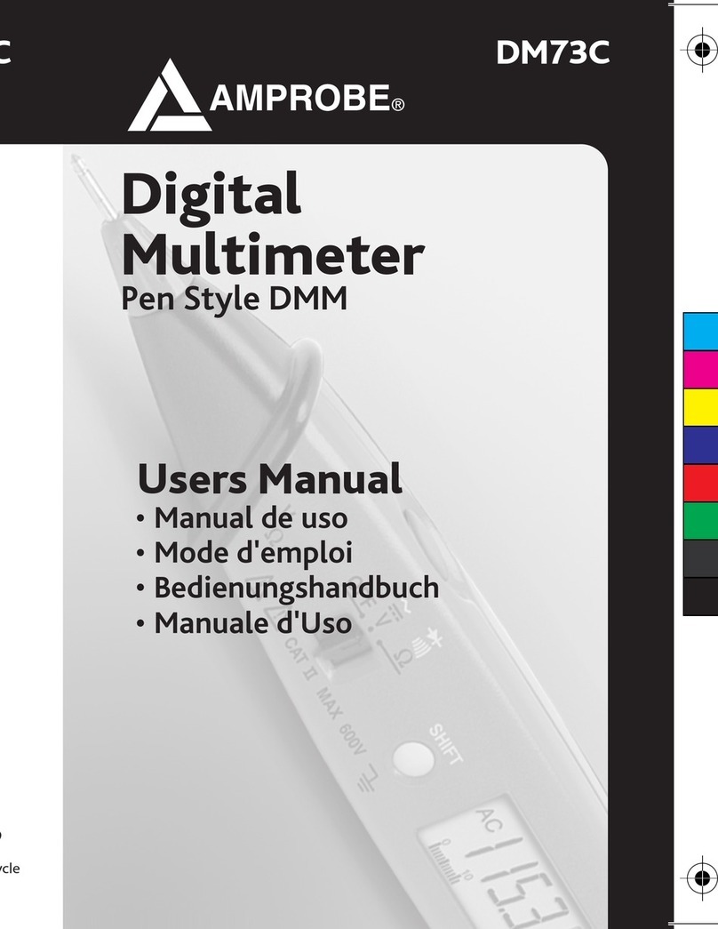
Amprobe AD105A User manual

AD105 man_cover.pdf 6/21/04 4:48:01 PM

AD105A
Digital Clamp-On Meter
Users Manual
•Bedienungshandbuch
•Manuale de Uso
•Mode d’emploi
PN 2729036
July 2006
©2006 AmprobeTest Tools.
All rights reserved. Printed in Taiwan

Limited Warranty and Limitation of Liability
Your Amprobeproduct will be free from defects in
material and workmanship for 1 year from the date of
purchase. This warranty does not cover fuses,
disposable batteries or damage from accident, neglect,
misuse, alteration, contamination, or abnormal
conditions of operation or handling. Resellers are not
authorized to extend any other warranty on Amprobe’s
behalf. To obtain service during the warranty period,
return the product with proof of purchase to an
authorized AmprobeTest Tools Service Center or to a
Amprobedealer or distributor. See Repair Section
above for details. THIS WARRANTY IS YOUR ONLY
REMEDY. ALL OTHER WARRANTIES - WHETHER
EXPRESS, IMPLIED OR STAUTORY - INCLUDING
IMPLIED WARRANTIES OF FITNESS FOR A
PARTICULAR PURPOSE OR MERCHANTABILITY, ARE
HEREBY DISCLAIMED. MANUFACTURER SHALL NOT
BE LIABLE FOR ANY SPECIAL, INDIRECT, INCIDENTAL
OR CONSEQUENTIAL DAMAGES OR LOSSES, ARISING
FROM ANY CAUSE OR THEORY. Since some states or
countries do not allow the exclusion or limitation of an
implied warranty or of incidental or consequential
damages, this limitation of liability may not apply to
you.

1
Digital Clamp-On Meter
Contents
Symbols.................................................................................................... 1
Warnings and Precautions........................................................................ 1
Introduction .............................................................................................. 1
Instrument Familiarization (See Fig. 1) ..................................................... 2
Measuring Procedures.............................................................................. 2
Specifications............................................................................................ 3
Troubleshooting........................................................................................ 4
Battery Replacement................................................................................. 4
Repair ....................................................................................................... 5
Symbols
B Battery W Refer to the manual
T Double
insulated B Alternating Current
F Direct
Current P Complies with EU
directives
Warnings and Precautions
•This instrument is EN61010-1:2001 certified for Installation
Category III (1000 V). It is recommended for use in distribution level
and fixed installations, as well as lesser installations, and not for
primary supply lines, overhead lines and cable systems
•This instrument must not be used on uninsulated conductors at a
voltage greater than 1000 V AC/DC
•Do not exceed the maximum input limits per function (see
specifications), nor any ratings marked on the instrument itself
•Never ground yourself when taking measurements. Do not touch
exposed metal pipes, outlets, fixtures, etc., which might be at
ground potential. Keep your body isolated from ground and never
touch exposed wiring, connections, or any live circuit conductors
•Do not operate the instrument in an explosive atmosphere
(flammable gases, fumes, vapor, dust)
•Do not use this or any piece of test equipment without proper
training
Introduction
Your shipping carton should include the digital clamp meter, a carrying
case, one 9 V battery (installed), a warranty card and this manual. If any of
the items are damaged or missing, immediately return the complete
package to the place of purchase for an exchange.

2
Instrument Familiarization (See Fig. 1)
1. Digital display: 3 ¾ digit LCD (max. reading 3999) plus auto polarity,
decimal point, N, ACB, DCFand P.
2. Wrist Strap: Prevents the instrument from slipping off the hand while
in use.
3. ON/OFF key.
4. Hz: This key selects the frequency mode. Press again to return to initial
function.
5. DCA AUTO Zero Key: Compensates the residual magnetism.
6. DC/AC Key: Selects between AC and DC current.
7. Jaw Opening Lever: Press lever to open transformer jaws. When
pressure on lever is released, the jaws close again.
8. Peak Hold Key: Press to hold the maximum measured value. P
annunciator is displayed.
9. Transformer Jaws: Designed to pick up the current flowing through the
conductor.
Measuring Procedures
AC Current/Frequency Measurement
1. Set the clamp meter to ACA mode by pressing DC/AC key.
2. Press the lever to open the transformer jaws and clamp one conductor
only, make sure that the jaw is firmly closed around the conductor.
3. Read the value from digital display.
4. To read frequency, press Hz key.
DC Current Measurement
1. Set the clamp meter to DCA mode by pressing DC/AC key.
2. Compensate the residual magnetism by pressing DCA Auto Zero key.
3. Press the lever to open the transformer jaws and clamp one conductor
only, make sure that the jaw is firmly closed around the conductor.
4. Read the value from digital display.
Note
For DC measurement, the reading is positive when the
current flows from the upper side to the lower side of the
instrument as shown in Fig. 1.
Peak Hold:
Depress the Peak Hold button to record maximum current values (RMS for
AC current). Any new maximum signal will be automatically stored and
displayed in the LCD. The Pannunciator indicates the Peak Hold feature is
invoked.

3
Specifications
General Specifications
Display: 3 3/4 Digit LCD, max. reading of 3999.
Polarity indication: automatic, “–” indicated; “+” implied.
Overrange Indication : “OL” or “– OL”.
Range selection: automatic; Measuring Rate: 2 /sec, nominal.
Position Error: ±1 % of Reading.
Type of Sensing: Hall effect sensing for AC and DC.
Low Battery Indication: N.
Auto Power Off: approx. 30 minutes after power on.
Environmental Conditions
Operating Temperature: 0 °C to +50 °C, <75 % R.H.
Storage Temperature: -20 °C to +60 °C, <80 % R.H., battery removed.
Temperature Coefficient: 0.2 x (Spec.Acc’y) / °C, < 18 °C or > 28 °C.
Power Requirement: Single 9 V PP3 battery (NEDA 1604,1EC 6F22)
Battery Life: Alkaline 40 hours typical.
Max / Conductor Size: 51 mm diameter or 24 x 60 mm busbar.
Size (LxWxD): 240x106x40 mm (9.5”x4.2”x1.6”); Weight: 420 grams
(14.8 oz)
Accessories: Battery (installed), manual and carrying case.
Agency Approvals: P
Safety: Meets EN61010-1:2001 Cat III 1000V,Class 2, Pollution Degree 2;
EN 61010-2-032; EMC: EN50081-1, EN50082-1
EMC: This product complies with requirements of the following European
Community Directives: 89/336/EEC (Electromagnetic Compatibility)
and 73/23/EEC (Low Voltage) as amended by 93/68/EEC (CE Marking).
However, electrical noise or intense electromagnetic fields in the vicinity of
the equipment may disturb the measurement circuit. Measuring
instruments will also respond to unwanted signals that may be present
within the measurement circuit. Users should exercise care and take
appropriate precautions to avoid misleading results when making
measurements in the presence of electronic interference.
Electrical Specifications
Accuracy is ±(%reading + number of digits) at 23 °C ±5 °C, < 75 % R.H.
Overload Protection, all functions and ranges: 2000 A AC/DC for 1 minute.
DC Current (autoranging)
Range Resolution Accuracy:
0 to 100 A 0.1 A ±(2.9 %rdg + 8 dgt)
100 A to 400 A 0.1 A ±(1.9 %rdg + 5 dgt)
400 A to 1000 A 1 A ±(2.9 %rdg + 5 dgt)

4
AC Current (40 – 400 Hz; autoranging)
Range Resolution Accuracy:
0 to 40 A 0.1 A ±(1.9 %rdg + 8 dgt)
40 A to 400 A 0.1 A ±(1.9 %rdg + 7 dgt)
400 A to 1000 A 1 A ±(2.9 %rdg + 5 dgt)
AC Conversion Type: AC conversions are ac-coupled, true rms responding,
calibrated to the rms value of a sine wave input. Accuracies are given for
sine wave at full scale. For distorted signals, add the following corrections:
for Crest Factor of 1.4 to 2.0, add 1.0 % to accuracy.
for Crest Factor of 2.0 to 2.5, add 2.5 % to accuracy.
for Crest Factor of 2.5 to 3.0, add 4.0 % to accuracy (0 – 400 A).
Frequency Counter
Range Resolution Accuracy:
4 KHz 1 Hz ±(0.5 %rdg + 3 dgt)
10 KHz 10 Hz ±(0.5 %rdg + 3 dgt)
Min. Input Frequency: 20 Hz
Sensitivity at 1 kHz to 10 kHz: 10 A RMS (<1 kHz: 6 A RMS)
Peak Hold
Range Resolution Accuracy:
LOW 0.1 A ±(3.0 %rdg + 10 dgt)
HIGH 1.0 A ±(3.0 %rdg + 10 dgt)
Troubleshooting
If there appears to be a malfunction during the operation of the meter, the
following steps should be performed in order to isolate the cause of the
problem:
1. Check the battery.
2. Review the operating instructions for possible mistakes in operating
procedure.
3. Check clamp against a known current source.
Except for the replacement of the battery, repair of the clamp should be
performed only by a Factory Authorized Service Center or by other
qualified instrument service personnel.
Front panel and case can be cleaned with a mild solution of detergent and
water. Apply sparingly with a soft cloth and let dry completely before
using. Do not use aromatic hydrocarbons or chlorinated solvents for
cleaning.
Battery Replacement
This instrument is powered by a single 9 V battery. Use the following
procedure to replace battery.
Turn the instrument off.
Position instrument face down, remove the two screws and lift off
back of case.
Replace battery, route wire away from top of battery and reassemble
case.

5
Repair
All test tools returned for warranty or non-warranty repair or for calibration
should be accompanied by the following: your name, company’s name,
address, telephone number, and proof of purchase. Additionally, please
include a brief description of the problem or the service requested and
include the test leads with the meter. Non-warranty repair or replacement
charges should be remitted in the form of a check, a money order, credit
card with expiration date, or a purchase order made payable to Amprobe
Test Tools.
In-Warranty Repairs and Replacement – All Countries
Please read the warranty statement and check your battery before
requesting repair. During the warranty period any defective test tool can be
returned to your AmprobeTest Tools distributor for an exchange for the
same or like product. Please check the “Where to Buy” section on
www.amprobe.com for a list of distributors near you. Additionally, in the
United States and Canada In-Warranty repair and replacement units can
also be sent to a AmprobeTest Tools Service Center (see below for
address).
Non-Warranty Repairs and Replacement – US and Canada
Non-warranty repairs in the United States and Canada should be sent to a
AmprobeTest Tools Service Center. Call AmprobeTest Tools or
inquire at your point of purchase for current repair and replacement rates.
In USA In Canada
AmprobeTest Tools AmprobeTest Tools
Everett, WA 98203 Mississauga, ON L4Z 1X9
Tel: 888-993-5853 Tel: 905-890-7600
Fax: 425-446-6390 Fax: 905-890-6866
Non-Warranty Repairs and Replacement – Europe
European non-warranty units can be replaced by your AmprobeTest
Tools distributor for a nominal charge. Please check the “Where to Buy”
section on www.amprobe.com for a list of distributors near you.
European Correspondence Address*
AmprobeTest Tools Europe
P.O. Box 1186
5602 BD Eindhoven
The Netherlands
*(Correspondence only – no repair or replacement available from this
address. European customers please contact your distributor).

6
.
O
O
P
/
O
A
Hz
I
9
3
2
7
4
1
5
8
6
AD105A

AD105A
Digital Clamp-On Meter
Users Manual
•Bedienungshandbuch
•Manuale de Uso
•Mode d’emploi
German
Deutsch

Beschränkte Gewährleistung und
Haftungsbeschränkung
Es wird gewährleistet, dass dieses Amprobe-Produkt
für die Dauer von einem Jahr ab dem Kaufdatum frei
von Material- und Fertigungsdefekten ist. Diese
Gewährleistung erstreckt sich nicht auf Sicherungen,
Einwegbatterien oder Schäden durch Unfälle,
Nachlässigkeit, Missbrauch, Änderungen oder
abnormale Betriebsbedingungen bzw. unsachgemäße
Handhabung. Die Verkaufsstellen sind nicht dazu
berechtigt, diese Gewährleistung im Namen von
Amprobezu erweitern. Um während der
Gewährleistungsperiode Serviceleistungen zu
beanspruchen, das Produkt mit Kaufnachweis an ein
autorisiertes AmprobeTest Tools Service-Center oder
an einen Amprobe-Fachhändler/-Distributor einsenden.
Einzelheiten siehe Abschnitt „Reparatur“ oben. DIESE
GEWÄHRLEISTUNG STELLT DEN EINZIGEN UND
ALLEINIGEN RECHTSANSPRUCH AUF
SCHADENERSATZ DAR. ALLE ANDEREN
GEWÄHRLEISTUNGEN - VERTRAGLICH GEREGELTE
ODER GESETZLICHE VORGESCHRIEBENE -
EINSCHLIESSLICH DER GESETZLICHEN
GEWÄHRLEISTUNG DER MARKTFÄHIGKEIT UND DER
EIGNUNG FÜR EINEN BESTIMMTEN ZWECK, WERDEN
ABGELEHNT DER HERSTELLER ÜBERNIMMT KEINE
HAFTUNG FÜR SPEZIELLE, INDIREKTE, NEBEN- ODER
FOLGESCHÄDEN ODER VERLUSTE, DIE AUF
BELIEBIGER URSACHE ODER RECHTSTHEORIE
BERUHEN. Weil einige Staaten oder Länder den
Ausschluss oder die Einschränkung einer implizierten
Gewährleistung sowie von Begleit- oder Folgeschäden
nicht zulassen, ist diese Gewährleistungsbeschränkung
möglicherweise für Sie nicht gültig.

1
Digital Clamp-On Meter
Inhalt
Symbole............................................................................................................ 1
Warnungen und Vorsichtsmaßnahmen............................................................. 1
Einleitung.......................................................................................................... 2
Vorstellung des Gerätes.................................................................................... 2
Meßprozeduren (Siehe Fig. 1)........................................................................... 2
Spezifikationen.................................................................................................. 3
Fehlersuche/Reparatur...................................................................................... 4
Reparatur.......................................................................................................... 5
Hinweis: Abbildungen befinden sich am Ende des englischen Abschnitts.
Symbole
B Batterie W Im Handbuch nachlesen.
T Schutzisoliert F Gleichstrom
P
Übereinstimmung mit
EU-Richtlinien B Wechselstrom
Warnungen und Vorsichtsmaßnahmen
•Dieses Gerät ist EN61010-1:2001-zertifiziert für
Installationskategorie III (1000 V). Anwendung ist empfohlen in
Installationen auf Verteilerebene und festen Installationen sowie
auch untergeordneten Installationen, jedoch nicht für
Hauptversorgungsleitungen, Freileitungen und Kabelsysteme
•Dieses Gerät darf nicht mit nicht-isolierten Leitern bei Spannungen
höher als 1000 V AC/DC verwendet werden
•Überschreiten Sie nie die kontinuierlichen Überlastgrenzen der
verschiedenen Meßfunktionen (siehe Spezifikationen) oder andere
Grenzen welche auf dem Gerät markiert sind
•Stromkreis während der Messung nicht berühren. Sich selbst
isolieren
•Gerät nicht in explosiver Umgebung verwenden

2
Einleitung
Die Verpackung sollte enthalten: ein digitales Zangenmultimeter, eine
Tragetasche, eine 9 V Batterie (im Gerät), eine Garantiekarte und diese
Anleitung. Sollte ein Teil beschädigt sein oder fehlen, kehren Sie bitte zur
Verkaufsstelle zurück für einen Umtausch.
Vorstellung des Gerätes (Siehe Fig. 1)
1. Digitale Anzeige: 3 3/4-stelliges LCD (max. Ablesung 3999), Polarität-,
Dezimalpunkt-, N, ACB, DCFund P.
2. Handschlaufe: Vermeidet ein Weggleiten des Gerätes während der
Messung.
3. Ein/Aus Schalter.
4. Hz: Diese Taste wählt Frequenzmessung. Erneut drücken um zur
vorigen Messung zurückzukehren.
5. DCA Nullabgleich: Kompensiert den Restmagnetismus.
6. DC/AC Taste: Wählt zwischen Gleich- und Wechselstrom.
7. Hebel zum Öffnen der Zange. Hebel drücken um Zange zu öffnen.
Zange schließt beim Loslassen des Hebels.
8. Peak Hold Taste: Mit dieser Taste können Sie den maximalen Wert
festhalten. Pwird angezeigt.
9. Stromzange: Überträgt den Strom der durch das Kabel fließt.
Meßprozeduren
Wechselstrom-/Frequenzmessung
1. Wechselstrom wählen durch DC/AC Taste zu drücken.
2. Zange öffnen, um einen Leiter bringen und schließen. Stellen Sie sicher
daß nur ein Leiter in der Zange ist und daß die Zange gut geschlossen
ist.
3. Meßwert ablesen.
4. Hz Taste drücken um Frequenz zu messen.
Gleichstrommessung
1. DC/AC Taste drücken um Gleichstrom (DCA) zu wählen.
2. “Auto Zero” Taste drücken um Restmagnetismus zu kompensieren.
3. Zange öffnen (durch drücken des Hebels), um ein Stromkabel bringen
und Zange schließen. Stellen Sie sicher daß nur ein Stromkabel in der
Zange ist und daß die Zange gut geschlossen ist.
4. Meßwert ablesen.
Anmerkung
Die Ablesung ist positiv wenn der Strom durch die
Zange von oben nach unten fließt (Siehe Fig. 1).
Anzeigenstop (Peak Hold)
“Peak Hold” Taste drücken um maximale Stromwerte festzuhalten (Echt
Effektivwerte). Eine neuer maximaler Wert wird automatisch gespeichert
und angezeigt. Pin der Anzeige gibt an daß die “Peak Hold” Funktion aktiv
ist.

3
Spezifikationen
Allgemeine Spezifikationen
Anzeige: 3-3/4 Digit LCD, 3999 Punkte.
Polaritätsanzeige: automatisch, “–” angezeigt; “+” unterstellt.
Überlastanzeige: “OL” oder “– OL”.
Bereichswahl: automatisch.
Meßrate: 2 /Sek, nominal.
Positionsfehler: ±1 % vom Meßwert.
Umsetzung: Hall Effekt für AC und DC.
Entladene Batterieanzeige: N
Automatische Abschaltung: ung. 30 Minuten nach Einschalten.
Umgebungsbedingungen
Betriebstemperatur: 0 °C bis +50 °C, <75 % R.F.
Lagertemperatur: -20 °C bis +60 °C, <80 % R.F., Batterie entfernt.
Temperaturkoeffizient: 0.2 x (Angegebene Genauigkeit) / °C, < 18 °C oder
> 28 °C.
Stromversorgung: 9 V PP3 Batterie (NEDA 1604,1EC 6F22).
Batterielebensdauer: Alkaline 40 Stunden typisch.
Max. Kabeldurchmesser: 51 mm oder 24 x 60 mm Stromschiene.
Abmessung (LxBxT): 240x106x40 mm ; Gewicht: 420 g.
Zubehör: Batterie (im Gerät), Anleitung, Tragetasche.
Zulassungen: P
Sicherheit: Gemäß EN61010-1:2001 Cat. III-1000V. Pollutionsgrad: Niveau
II, EN61010-2-032; EMC: Gemäß EN50081-1, EN50082-1
EMC:
Dieses Produkt beantwortet an die Bestimmungen der folgenden EWG
Richtlinien: 89/336/EEC (Elektromagnetische Kompatibilität) und
73/23/EEC (Niedrige Spannung) geändert durch 93/68/EEC (CE
Marking).
Elektrisches Rauschen und starke magnetische Felder in der direkten
Umgebung des Meßgerätes können jedoch den Meßkreis beeinflussen.
Das Gerät kann auch durch Störsignale im gemessenen Schaltkreis
beeinflußt werden. Der Anwender muß Vorsichtsmaßnahmen treffen
um irreführende Meßergebnisse bei Messungen in der Umgebung von
starken elektromagnetischen Feldern zu vermeiden.
Elektrische Spezifikationen
Genauigkeit ist ±(%vMW + Anzahl Digits) bei 23 °C ±5 °C, <75 % R.F.
Überlastschutz, alle Funktionen und Bereiche: 2000 A AC/DC für 1 Minute.
Gleichstrom (Autobereich)
Bereich Auflösung Genauigkeit
0 bis 100 A 0.1 A ±(2.9 %vMW + 8 Dgt)
100 A bis 400 A 0.1 A ±(1.9 %vMW + 5 Dgt)
400 A bis 1000 A 1 A ±(2.9 %vMW + 5 Dgt)
Wechselstrom (40 – 400 Hz; Autobereich)
Bereich Auflösung Genauigkeit:
0 bis 40 A 0.1 A ±(1.9 %vMW + 8 Dgt)
40 A bis 400 A 0.1 A ±(1.9 %vMW + 7 Dgt)
400 A bis 1000 A 1 A ±(2.9 %vMW + 5 Dgt)

4
Umsetzung: AC gekuppelt, echt-effektivwertmessend, kalibriert für
Sinuswelle. Genauigkeiten für Sinuswelle im Endbereich. Für verzerrte
Signale bitte folgende Crest Faktor Korrekturen anbringen:
Crest Faktor 1.4 bis 2.0: 1.0 % zur Genauigkeit hinzufügen.
Crest Faktor 2.0 bis 2.5: 2.5 % zur Genauigkeit hinzufügen.
Crest Faktor 2.5 bis 3.0: 4.0 % zur Gen. hinzufügen (0 - 400A).
Frequenzzähler
Bereich Auflösung Genauigkeit
4 KHz 1 Hz ±(0.5 %vMW + 3 Dgt)
10 KHz 10 Hz ±(0.5 %vMW + 3 Dgt)
Min. Eingangsfrequenz: 20 Hz
Empfindlichkeit bei 1 kHz bis 10 kHz: 10 A eff. (<1 kHz: 6 A eff)
Peak Hold
Bereich Auflösung Genauigkeit
LOW 0.1 A ±(3.0 %vMW + 10 Dgt)
HIGH 1.0 A ±(3.0 %vMW + 10 Dgt)
Fehlersuche/Reparatur
Bei Problemen bitte folgendes prüfen:
1. Batterie Ladung,
2. Meßprozedur
3. Einen bekannten Stromwert mit der Zange prüfen.
Mit Ausnahme des Batteriewechsels sollte jede Reparatur der Stromzange
nur durch eine Wavetek-anerkannte Servicestelle vorgenommen werden.
Das Gehäuse kann mit einer milden Seifenlösung gereinigt werden. Vor
Gebrauch gut trocknen lassen.
Batterieustausch
Das Geräte wird durch eine 9 V Batterie betrieben. Zum Betteriewechel
1. Gerät ausschalten.
2. Rückwand losschrauben und abheben.
3. Batterie wechsein, Drähte freilegen und Gehäuse wieder
zusammensetzen.

5
Reparatur
Zu allen Geräten, die zur Reparatur oder Kalibrierung im Rahmen der
Garantie oder außerhalb der Garantie eingesendet werden, muss folgendes
beigelegt werden: Name des Kunden, Firmenname, Adresse,
Telefonnummer und Kaufbeleg. Zusätzlich bitte eine kurze Beschreibung
des Problems oder der gewünschten Wartung sowie die Messleitungen
dem Messgerät beilegen. Die Gebühren für Reparaturen außerhalb der
Garantie oder für den Ersatz von Instrumenten müssen als Scheck,
Geldanweisung, Kreditkarte (Kreditkartennummer mit Ablaufdatum)
beglichen werden oder es muss ein Auftrag an AmprobeTest Tools
formuliert werden.
Garantiereparaturen oder -austausch - alle Länder
Bitte die Garantieerklärung lesen und die Batterie prüfen, bevor
Reparaturen angefordert werden. Während der Garantieperiode können
alle defekten Geräte zum Umtausch gegen dasselbe oder ein ähnliches
Produkt an den AmprobeTest Tools-Distributor gesendet werden. Ein
Verzeichnis der zuständigen Distributoren ist im Abschnitt “Where to Buy”
(Verkaufsstellen) auf der Website www.amprobe.com zu finden. Darüber
hinaus können in den USA und in Kanada Geräte an ein AmprobeTest
Tools Service-Center (Adresse siehe weiter unten) zur Reparatur oder zum
Umtausch eingesendet werden.
Reparaturen und Austausch außerhalb der Garantie - USA und Kanada
Für Reparaturen außerhalb der Garantie in den Vereinigten Staaten und in
Kanada werden die Geräte an ein AmprobeTest Tools Service-Center
gesendet. Auskunft über die derzeit geltenden Reparatur- und
Austauschgebühren erhalten Sie von AmprobeTest Tools oder der
Verkaufsstelle.
In den USA: In Kanada:
AmprobeTest Tools AmprobeTest Tools
Everett, WA 98203 Mississauga, ON L4Z 1X9
Tel.: 888-993-5853 Tel.: 905-890-7600
Fax: 425-446-6390 Fax: 905-890-6866
Reparaturen und Austausch außerhalb der Garantie - Europa
Geräte außerhalb der Garantie können durch den zuständigen Amprobe
Test Tools-Distributor gegen eine Gebühr ersetzt werden. Ein Verzeichnis
der zuständigen Distributoren ist im Abschnitt „Where to Buy“
(Verkaufsstellen) auf der Website www.amprobe.com zu finden.
Korrespondenzanschrift für Europa*
AmprobeTest Tools Europe
P. O. Box 1186
5602 BD Eindhoven
Niederlande
*(Nur Korrespondenz – keine Reparaturen, kein Umtausch unter dieser
Anschrift. Kunden in Europa wenden sich an den zuständigen Distributor).

6

AD105A
Digital Clamp-On Meter
Users Manual
•Bedienungshandbuch
•Manuale de Uso
•Mode d’emploi
Spanish
Español

Garantía limitada y Limitación de responsabilidad
Su producto Amprobeestará libre de defectos de
material y mano de obra durante 1 año a partir de la
fecha de adquisición. Esta garantía no cubre fusibles,
baterías descartables o daños que sean consecuencia
de accidentes, negligencia, uso indebido, alteración,
contaminación o condiciones anormales de operación o
manipulación. Los revendedores no están autorizados a
extender ninguna otra garantía en nombre de Fluke.
Para obtener servicio durante el período de garantía,
regrese el producto con una prueba de compra a un
centro de servicio autorizado por Amprobede equipos
de comprobación o a un concesionario o distribuidor de
Amprobe. Consulte la sección Reparación que
aparece más arriba para obtener detalles. ESTA
GARANTÍA CONSTITUYE SU ÚNICO RESARCIMIENTO.
TODAS LAS DEMÁS GARANTÍAS, TANTO EXPRESAS,
IMPLÍCITAS O ESTATUTARIAS, INCLUYENDO LAS
GARANTÍAS IMPLÍCITAS DE ADECUACIÓN PARA UN
PROPÓSITO DETERMINADO O COMERCIABILIDAD,
QUEDAN POR LA PRESENTE DESCONOCIDAS. El
fabricante no deberá ser considerado responsable de
ningún daño o pérdida tanto especiales, indirectos,
contingentes o resultantes que surjan de cualquier
causa o teoría. Debido a que ciertos estados o países no
permiten la exclusión o limitación de una garantía
implícita o de los daños contingentes o resultantes, esta
limitación de responsabilidad puede no regir para usted.

1
Digital Clamp-On Meter
Contenidos
Símbolos................................................................................................... 1
Advertencias y Precauciones .................................................................... 1
Introducción.............................................................................................. 2
Familiarización Con El Instrumento (vea Fig. 1) ........................................ 2
Procedimientos de Medida........................................................................ 2
Especificaciones........................................................................................ 3
Mantenimiento.......................................................................................... 4
Sustitución de la Pila................................................................................. 4
Reparación................................................................................................ 5
Nota: Las figuras se muestran al final de la sección en inglés.
Símbolos
B Batería W Consulte el manual
T Aislamiento doble F Corriente continua
P
Cumple con las
directivas de la Unión
Europea.
B Corriente alterna
Advertencias y Precauciones
•Este instrumento tiene la certificación EN61010-1:2001 para
instalaciones de categoría III (1000 V). Se recomienda para uso en
instalaciones fijas y al nivel de distribución, así como en
instalaciones menores, y no para líneas de suministro primario,
líneas aéreas y sistemas de cable
•No debe utilizar este instrumento sobre hilos sin aislar a tensiones
superiores a 1000 V CA/CC
•No supere nunca los límites de entrada para las diferentes
funciones (vea Especificaciones), ni los límites marcados en el
instrumento
•Nunca se ponga Ud. a tierra cuando esté tomando medidas. No
toque nunca circuitos expuestos
•No utilice el instrumento en ambientes potencialmente explosivos
Table of contents
Languages:
Other Amprobe Multimeter manuals

Amprobe
Amprobe AM-560 User manual

Amprobe
Amprobe AM-1250 User manual

Amprobe
Amprobe KWC-2000 User manual

Amprobe
Amprobe AM-500 User manual

Amprobe
Amprobe 30XR-A User manual

Amprobe
Amprobe AM50 User manual

Amprobe
Amprobe DM78C User manual

Amprobe
Amprobe 37XR-A User manual

Amprobe
Amprobe DM78B User manual

Amprobe
Amprobe 30XR-A User manual

Amprobe
Amprobe AC75B User manual

Amprobe
Amprobe 37XR-A User manual

Amprobe
Amprobe HD110C User manual

Amprobe
Amprobe AM-560 User manual
Amprobe
Amprobe ACD-11 User manual

Amprobe
Amprobe 34XR-A User manual

Amprobe
Amprobe 38XR-A User manual
Amprobe
Amprobe 34XR-A User manual

Amprobe
Amprobe DM9C User manual

Amprobe
Amprobe ACD-14 PLUS User manual