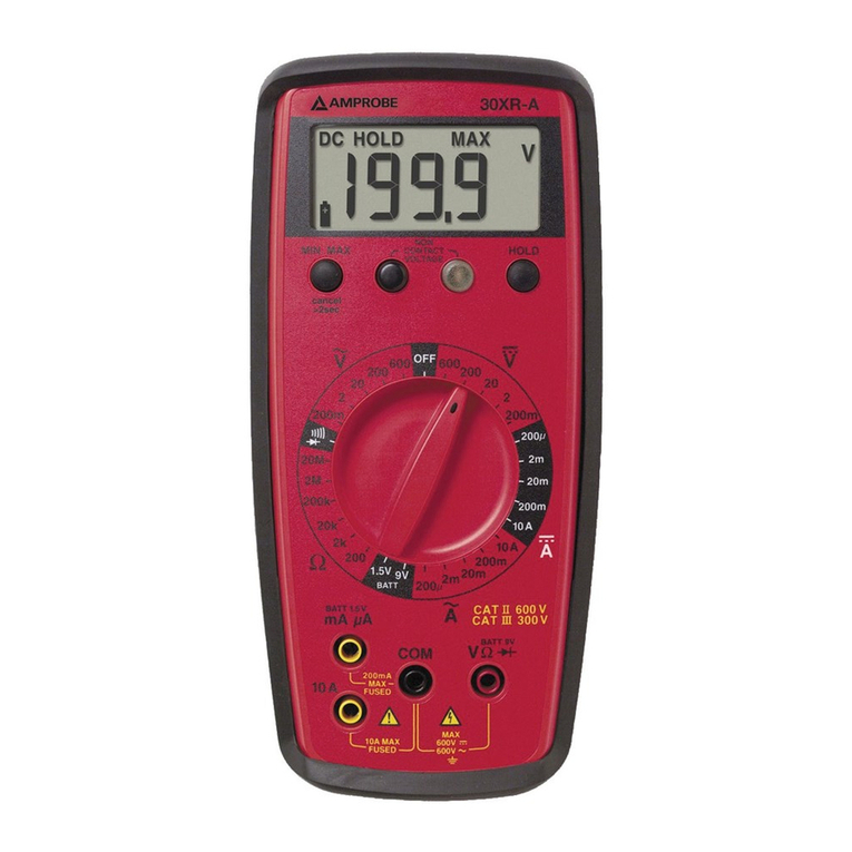
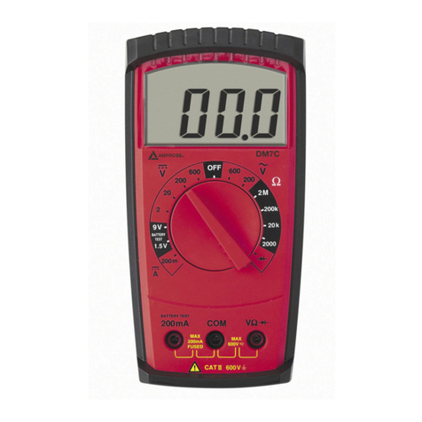
Amprobe DM7C User manual

Test Equipment Depot - 800.517.8431 - 99 Washington Street Melrose, MA 02176
FAX 781.665.0780 - TestEquipmentDepot.com

Contents
Introduction..........................................................................................2
Contents ..........................................................................................3
Transport and Storage ..........................................................................3
Safety ..........................................................................................3
Appropriate Usage ..............................................................................4
Feature Diagram ..................................................................................4
Operation ..........................................................................................5
Voltage Measurement ................................................................5
DC Voltage Measurement ..........................................................5
AC Voltage Measurement ..........................................................5
Resistance Measurement ..........................................................6
Battery Test................................................................................6
Diode Test..................................................................................7
Current Measurement ..............................................................7
Current Measurement 200 mA ..................................................8
Changing the batteries ..........................................................................8
Fuse replacement..................................................................................9
Maintenance ........................................................................................9
Cleaning ....................................................................................9
Calibration Interval ....................................................................9
Specifications ......................................................................................10
Warranty ..........................................................................................11
Repair ..........................................................................................12
1
DM7C Multimeter
Users Manual
Test Equipment Depot - 800.517.8431 - 99 Washington Street Melrose, MA 02176
FAX 781.665.0780 - TestEquipmentDepot.com

References marked on instrument or in users manual
The users manual contains information and references, necessary for safe
operation and maintenance of the instrument. Prior to using the instrument the
user is kindly requested to thoroughly read the users manual and comply with it
in all sections. Failure to read the users manual or to comply with the warnings
and references contained herein can result in serious bodily injury or instrument
damage
Introduction
The Amprobe Multimeter DM7C is a universal, multi-purpose electrical measuring in-
strument. It comply with the standards DIN VDE 0411 and EN 61010, and p r o v i d e
safe, reliable operation. The multimeter is a valuable tool for all sorts of measurements
in both trade and industry.
• 3 1/2 digit LC Display, max. 1999 digits
• manual measurement range selection
• AC and DC voltage measurement up to 600 V
• DC Current measurement up to 200 mA
• Resistance measurement up to 2 MOhm
• Diode test
• Battery test for 1.5 V and 9 V batteries
After unpacking, check that the instrument is complete, and that all accessories are
present.
2
Warning of a potential danger,
comply with users manual. Equipment protected
throughout by double insulation
or reinforced insulation.
Caution! Dangerous voltage.
Danger of electrical shock.
Canadian Standards Association.
Conformity symbol, the instru-
ment complies with the valid di-
rectives. It complies with the
EMC Directive (89/336/EEC)
and the Low Voltage Directive
(73/23/EEC) with their valid
standards.
Reference. Please use utmost
attention.
Symbol for the marking of elec-
trical and electronic equipment
(WEEE Directive 2002/96/EC).

Contents
1 pc. Amprobe Multimeter DM7C
1 pc. Holster
2 pcs. Test Leads (1ea. red, 1ea. black)
1 pc. Battery 9 V IEC 6F22 or 6LR61
1 pc. Users Manual
Transport and Storage
• Please keep the original packaging for later transport, e.g. for calibration. Any
transport damage due to faulty packaging will be excluded from warranty claims.
• Inordertoavoidinstrument damage, it is advised to remove batteries whennotusing
the instrument over a certain time period. However, should the instrument be
contaminated by leaking battery cells, you are kindly requested to return it to the
factory for cleaning and inspection.
• Instruments must be stored in dry and closed areas. In the case of an instrument
being transported in extreme temperatures, a recovery time of minimum 2 hours is
required prior to instrument operation.
Safety
• The Amprobe multimeter DM7C has been manufactured and tested to comply with
the safety regulations for electronic measuring equipment contained in IEC61010
and EN 61010, and left the factory in a safe condition. To maintain this condition, the
user must observe the safety instructions contained in this users manual.
• To avoid electric shock, safety measures must be observed when working with volt-
ages higher than 120 V (60 V) DC or 50 V (25 V) RMS AC. These are the
values of threshold contact voltages given by DIN VDE.
• Before each measurement make sure that the test leads and the instrument are un-
damaged.
• Onlyhandle testleadsand probeson thegripsprovided.Avoidtouchingprobesunder
any circumstances.
• Measurements in dangerous proximity of electrical installations are only to be exe-
cuted when instructed by a responsible electrical specialist, and never alone.
• The relevant safety regulations for electrical plant and equipment must be
observed during all operations.
• The instrument must only be used in the specified ranges.
• Before opening the instrument, it must be disconnected from all circuits.
• Protect the instrument from prolonged exposure to direct sunlight.
3

Appropriate Usage
• The instrument may only be used under those conditions and for those purposes for
which it was conceived. For this reason, in particular the safety references, the tech-
nical data including environmental conditions and the usage in dry environments
must be followed.
• When modifying or changing the instrument, the operational safety is no longer en-
sured.
• The instrument may only be opened by an authorised service technician, e.g. for fuse
replacement.
Feature Diagram
1. LCD
2. Measurement function selection switch
3. Input socket for measurement ranges
4. Ground connection for all measurement ranges
5. Input socket for current measurement range 200 mA
4
1
2
3
4
5

Operation
Measurements in dangerous proximity of electrical systems are only to be carried
out in compliance with the instructions of a responsible electronics technician,
and never alone.
Test leads and test probes may only be touched at handle surfaces provided. Ab-
solutely avoid the direct contact of the test probes. Prior to switching to a new
measurement range or a new type of measurement, remove all connections from
UUT.
Measurements have to be carried out by respecting the standards.
Voltage Measurement
To avoid electrical shock, the valid safety measures and VDE directives strictly
have to be met concerning excessive contact voltage when working with voltages
exceeding 120V (60V) DC or 50V (25V)rms AC.
DC Voltage Measurement
1) Select measurement range (2V, 20V, 200V or 600V) via measurement
function selection switch.
2) Connect the black test lead to the COM socket and the red test lead to the
socket.
3) Connect test leads to UUT.
4) Read the measurement result displayed on the screen.
If display shows ”1” on the left, change selection to next highest voltage range.
AC Voltage Measurement
1) Select measurement range (200V or 600V) via measurement function
selection switch.
2) Connect the black test lead to the COM socket and the red test lead to the
socket.
3) Connect test leads to UUT.
4) Read the measurement result displayed on the screen.
If display shows ”1” on the left,, change selection to next highest voltage range.
5

Resistance Measurement
Prior to any resistance measurement it has to be ensured that the resistor to be
tested does not have voltage across it. Failure to comply with this prescription can
lead to dangerous user injuries or cause instrument damage. Addition-
ally, foreign voltages falsify the measurement result.
1) Select measurement range (2000!, 20k!, 200 k!or 2 M!) via measurement
function selection switch.
2) Connect the black test lead to the COM socket and the red test lead to the
socket.
3) Connect the test leads to UUT.
4) Read the measurement result displayed on the screen.
If display shows ”1” on the left, change selection to next highest resis.-range.
Battery Test
1) Select measurement range 9V or 1.5V via measurement function selection switch
.
2) Connect the black test lead to the COM socket and the red test lead to the
BATTERY TEST socket.
3) Connect test leads to UUT/Battery.
4) Read the measurement result displayed on the screen.
6

Diode Test
Prior to any diode test, it must be ensured, that the diode to be tested does not
have voltage across it. Failure to comply with this prescription can lead to dan-
gerous user injuries or cause instrument damage. Additionally, foreign
voltages falsify the measurement result.
Resistors and semiconductor paths in parallel to the diode cause falsified meas-
urement results.
1) Position measurement function selection switch to measurement range.
2) Connect the black test lead to the COM socket and the red test lead to the
socket.
3) Connect test leads to UUT.
4) Read the measurement result displayed on the screen.
Current Measurement
Ensure that the measurement circuit is not live when connecting the
measurement instrument.
The instruments may only be used in current circuits protected at 16 A up to a
nominal voltage of 600 V.
The nominal cross section of connecting line has to be respected and a safe con-
nection has to be ensured.
After instrument fuse tripping eliminate the cause for the tripping prior to fuse re-
placement.
7

Current Measurement 200 mA
1) Position measurement function selection switch to 200m measurement range.
2) Connect the black test lead to the COM socket and the red test lead to the 200mA
socket.
3) Connect test leads to UUT.
4) Read the measurement result displayed on the screen.
Changing the batteries
Prior to battery replacement, disconnect the instrument from any circuits.
Only use batteries as described in the specifications.
If the symbol for Low-battery appears in the upper left corner of the display, the
battery must be changed.
This is carried out as follows:
1) SeparatetheAmprobemultimeter DM7C from any circuit,andremovethe test leads.
2) Switch the instrument off
3) Open the housing by removing the 4 screws on the rear face.
4) Remove the old battery.
5) Insert a new battery (type 1 x 9 V IEC 6F22 or 6LR61), taking care that the polarity
is correct. Make sure that no wires are trapped between the 2 halves of the housing,
and close it again.
6) The instrument is now ready for further use.
Please consider your environment when you dispose of. They belong in a dispos-
al area for hazardous waste.
Please, comply with the respective valid regulation regarding the return,
recycling and disposal of used batteries.
If an instrument is not used over an extended time period, the batteries must be
removed. Should the instrument be contaminated by leaking battery cells, the in-
strument has to be returned for cleaning and inspection to the factory.
8

Fuse replacement
Prior to fuse replacement, disconnect the instrument from any circuits.
Only use fuses of voltage and current values as described in the specifications.
Using auxiliary fuses, in particular short-circuiting fuse holders is prohibited and
can cause instrument destruction or serious bodily injury of operator.
1) SeparatetheAmprobemultimeter DM7C from any circuit,andremovethe test leads.
2) Switch the instrument off and remove the holster.
3) Open the housing by removing the 4 screws on the rear face.
4) Remove the defective fuse
5) Insert a new fuse. Make sure that no wires are trapped between the 2 halves of the
housing, and close it again.
6) The instrument is now ready for further use.
Maintenance
Provided it is used in accordance with the users manual, the instrument needs no spe-
cial maintenance.
Cleaning
If the instrument is dirty after daily usage, it is advised to clean it by using a damp
cloth and a mild household detergent.
Prior to cleaning, ensure that instrument is switched off and disconnected from
external voltage supply and any other instruments connected (such as UUT, con-
trol instruments, etc.).
Never use acid detergents or dissolvants for cleaning.
Calibration Interval
We suggest a calibration interval of one year. If the instrument is used very often or if
it is used under rough conditions we recommend shorter intervals. If the instrument
is used only a few times a year, the calibration interval can be extended to 3 years.
9

Specifications (at 23° C ± 5° C, max. 75 % rel. humidity)
Display: 3 1/2 digits, LC-Display
Total display: 1999 digit
Overload display: the left ”1” is displayed
Polarity display: automatic
Battery status display: Battery symbol appears (7.2 V)
Overvoltage class: CAT II 600 V
Degree of contamination: 2
Power supply: Battery 9V IEC 6F22 or 6LR61
Power consumption: approx. 1,5 mA (typical)
Dimensions: 170 x 85 x 50 mm incl. Holster
Weight: approx.. 410 g (incl. Holster)
Ambient conditions:
Operation temperature: 0...50°C (0...80% rel. humidity)
Storage temperature: -10...60°C (0...80% rel.humidity)(without battrie)
Height above sea level: up to 2000 m
Overload protection:
Fuse (mA) : FF200mA / 700V / 50kA , 6x32mm
Temperature coefficient: 0,15 x specified accuracy per 1°C (<18°C and >28°C)
Voltage DC
Range Resolution Accuracy Overload protection
2 V 1 mV ± (1.2%
20 V 10 mV rdg. + 3 digit) 600 V DC/ACeff
200 V 100 mV
600 V 1 V
Input Impedance 1 MOhm
Voltage AC (40...1 kHz)
Range Resolution Accuracy
40...100 Hz 100Hz...1kHz
200 V 100 mV ±(1.5% rdg.+3digit) ±(2.5% rdg.+ 3digit)
600 V 1 V
Overload protection: 600 V DC/ACeff
Input Impedance: 460 kOhm
Battery Test
Range Resolution Accuracy Overload protection
1.5V 10 mV ±(2.5% rdg 600 V DC/ACeff
9 V 10 mV +3 digit)
10

Current DC
Range Resolution Accuracy Overload protection
200 mA 100 µA ± (2,.5% rdg. 600 V DC/ACeff
+ 3 digit)
Resistance
Range Resolution Accuracy Overload protection
2000 Ohm 1 Ohm ± (1.5% rdg.
20 kOhm 10 Ohm + 3 digit) 600 V DC/ACeff
200 kOhm 100 Ohm
2 MOhm 1 kOhm
Test Voltage < 3,2 V
Diode Test
Range Resolution Test Voltage Test Current
Diode 1 mV < 3.2 V < 1 mA
Overload protection 600 V DC/ACeff
Limited Warranty and Limitation of Liability
Your Amprobe product will be free from defects in material and workmanship for 1 year
from the date of purchase. This warranty does not cover fuses, disposable batteries or
damage from accident, neglect, misuse, alteration, contamination, or abnormal
conditions of operation or handling. Resellers are not authorized to extend any other
warranty on Amprobe’s behalf. To obtain service during the warranty period, return the
product with proof of purchase to an authorized Amprobe Test Tools Service Center or
to an Amprobe dealer or distributor. See Repair Section for details. THIS WARRANTY
IS YOUR ONLY REMEDY. ALL OTHER WARRANTIES - WHETHER EXPRESS, IMPLIED
OR STAUTORY - INCLUDING IMPLIED WARRANTIES OF FITNESS FOR A PARTICULAR
PURPOSE OR MERCHANTABILITY, ARE HEREBY DISCLAIMED. MANUFACTURER
SHALL NOT BE LIABLE FOR ANY SPECIAL, INDIRECT, INCIDENTAL OR
CONSEQUENTIAL DAMAGES OR LOSSES, ARISING FROM ANY CAUSE OR THEORY.
Since some states or countries do not allow the exclusion or limitation of an implied
warranty or of incidental or consequential damages, this limitation of liability may not
apply to you.
11
Test Equipment Depot - 800.517.8431 - 99 Washington Street Melrose, MA 02176
FAX 781.665.0780 - TestEquipmentDepot.com
Other manuals for DM7C
1
Table of contents
Other Amprobe Multimeter manuals

Amprobe
Amprobe DM73C User manual

Amprobe
Amprobe 5XP-A User manual

Amprobe
Amprobe Hexagon 60 User manual

Amprobe
Amprobe PM51A User manual

Amprobe
Amprobe ACDC-400 User manual

Amprobe
Amprobe ac68C User manual

Amprobe
Amprobe AM-500 User manual

Amprobe
Amprobe ACD-10 TRMS-PLUS User manual

Amprobe
Amprobe AU92 User manual

Amprobe
Amprobe DM78B User manual

Amprobe
Amprobe DM7C User manual

Amprobe
Amprobe KWC-2000 User manual

Amprobe
Amprobe AM-420 User manual

Amprobe
Amprobe ACDC-3000 User manual

Amprobe
Amprobe AM-52 User manual

Amprobe
Amprobe AM-250 User manual

Amprobe
Amprobe PXP-A User manual

Amprobe
Amprobe DM78C User manual

Amprobe
Amprobe ACDC-600A User manual

Amprobe
Amprobe AM-100 User manual