Acrosser Technology AR-B6005 User manual

1
AR-B6005 Board
User Manual

Copyright
All Rights Reserved.
Manual’s first edition:
For the purpose of improving reliability, design and function, the information in this
document is subject to change without prior notice and does not represent a commitment on the
part of the manufacturer.
In no event will the manufacturer be liable for direct, indirect, special, incidental, or
consequential damages arising out of the use or inability to use the product or documentation,
even if advised of the possibility of such damages.
This document contains proprietary information protected by copyright. All rights are
reserved. No part of this Manual may be reproduced by any mechanical, electronic, or other
means in any form without prior written permission of the manufacturer.
Trademarks
AR-B6005 are registered trademarks of Acrosser; IBM PC is a registered trademark of the
International Business Machines Corporation; Pentium is a registered trademark of Intel
Technologies Inc; Phoenix is a registered trademark of Phoenix Software International Inc;
other product names mentioned herein are used for identification purposes only and may be
trademarks and/or registered trademarks of their respective companies.
2

Table of Contents
Chapter 1 Introduction.................................................................................................................................4
1.1 Specifications.................................................................................................................................4
1.2 Package Contents...........................................................................................................................5
1.3 Block Diagram...............................................................................................................................5
Chapter 2 H/W Information.........................................................................................................................6
2.1 Mainboard illustration (Top Side)..................................................................................................6
2.2 Locations of I/O ports & Jumper settings definition……………………………………………..8
Chapter 3 BIOS Settings............................................................................................................................16
3.1 Main Setup...................................................................................................................................17
3.2 Advanced Chipset Setup..............................................................................................................19
3.3 Superio Setup...............................................................................................................................20
3.4 Security Setup..............................................................................................................................22
3.5 Boot setup ....................................................................................................................................23
3.6 Exit Setup.....................................................................................................................................24
Chapter 4 Function Description.................................................................................................................28
4.1 DC Power input connection.........................................................................................................28
4.2 Digital Inputs ...............................................................................................................................28
4.3 Digital Outputs.............................................................................................................................29
4.4 Watchdog Timer...........................................................................................................................30
4.5 RS-232 Ports................................................................................................................................30
4.6 Serial ATA (SATA).......................................................................................................................32
4.7 USB..............................................................................................................................................32
Chapter 5 Driver And Utility Installation..................................................................................................33
5.1 Driver CD Interface Introduction.................................................................................................33
Chapter 6 Software Installation and Programming Guide.........................................................................47
6.1. CAN bus......................................................................................................................................47
6.2 GPIO and Watchdog ....................................................................................................................49
6.3 Power Subsystem.........................................................................................................................49
6.4 I-Button Function.........................................................................................................................50
6.5 API List and Descriptions............................................................................................................50
6.5.1 CAN Bus...............................................................................................................................50
6.5.2 GPIO and Watchdog .............................................................................................................57
6.5.3 Power Subsystem..................................................................................................................59
6.5.4 I-Button.................................................................................................................................65
Appendix A................................................................................................................................................66
3

Chapter 1 Introduction
AR-B6005 Series with Intel Atom E640 with smart power on board processor is a multi-function
In-Vehicle computer, which is suitable for using in all kind of applications. Besides basic I/O
ports like VGA, DVI, USB, COM. LAN, and GPIO, AR-B6005 has complete wireless solutions
for GPS / 3.5G / WiFi / Bluetooth selection, 2.5” SSD, DC output for monitor, Driver ID, and
embedded CAN Bus function to allow micro-controllers and devices to communicate with each
other in vehicle. In addition, AR-B6005 has intelligent power management function with
software utility to monitor power status and control power sequence, and also compliant with
most industry standards for in-vehicle usage including CE, FCC, and E-Mark.
1.1 Specifications
CPU Intel Atom E640 CPU
Chipset Intel EG20T chipset
Memory DDR2 1GB on board
Ethernet 1 x RJ45 10/100/1000Mbps LAN ports
Serial Port 2 x RS-232 (DB9) & 1 x RS-232/422/485 (DB9)
USB 2 x USB 2.0 (1 x external port, 1 x combo connector)
Flexible GPIO ports (8 bits digital I/O (4 x IN & 4 x OUT) & CAN bus
Driver ID (Use I-Button) can certified driver
CF 1 x external CF socket
SATAII 1 x 2.5” HDD bay, Only support SSD
Video VGA (DB15) & DVI-D
Audio Line-out & MIC connector
Mini-PCIe 2 x mini-PCIe slot for expansion (Capable for WiFi / 3.5G)
OS support Windows XP (32 bit), Linux fedora 14 (32/64 bit), Ubuntu 10 (32/64 bit)
9 ~ 32V DC input & customer define power management mode for ODM
12V DC 20W output connector for monitor
4

1.2 Package Contents
Check if the following items are included in the package.
Quick Manual
AR-B6005 board
1 x Software Utility CD
1.3 Block Diagram
5

Chapter 2 H/W Information
This chapter describes the installation of AR-B6005. At first, it shows the Function
diagram and the layout of AR-B6005. It then describes the unpacking information which you
should read carefully, as well as the jumper/switch settings for the AR-B6005 configuration.
2.1 Mainboard illustration (Top Side)
6

Mainboard illustration (Bottom Side)
BH1
System RTC battery socket In
tel Platform Control Hub(PCH) EG20T
MINIPCIE1
MINI PCI-E socket 1
MINIPCIE2
MINI PCI-E socket 2
Intel Atom E620/E640 CPU
7

2.2 Locations of I/O ports & Jumper settings definition
8

MINIPCIE1
Mini-PCI Express Card connector COMBO1
Combo connecter
SIM1
SIM card Holder CN4
RJ45 & USB ports (USB1)Connector .
BT1
Bluetooth module connector.
AUDIO1
Line Out & Remote switch & Mic in
phone jack.
GPS1
GPS module connector. LED2
3 in 1 LED for Power, HDD, Status
LED.
CF1
CF CARD SOCKET FUSE1
For Fuse connector
GPIO1
D-SUB 15 pin for External GPIO
connector.
PWR2
Power Input Terminal Block
Connector
COM1_COM3
D-SUB 9 pin for COM1,COM3 RS232
connector PIC1
PIC Programming connector.
SW1
For RS-422,RS-485 function select. MINIPCIE2
Mini-PCI Express Card connector
SW2
For RS-422,RS-485 function select. SATA_PWR1
For SATA Power Connector #1
SW3
For RS-422,RS-485 function select. SATA1
SATA device connector #1
CCMOS1
CMOS Memory Clearing Header
COM2_485
Pin Header for COM2 use
RS-422/485 function
BH1
CR2032 Battery Hold Connector.
COM2
Pin Header for COM2 use RS-232
function
DVI1
DVI connecter SPI1
BIOS Programmable HEADER.
9

2.2.1 Connectors and Jumper Settings
1, 21. MINIPCIE1, MINIPCIE2 ( Mini-PCIe
Connector ) 2. SIM1 Connector
Mini-PCIe x1 Connector
SIM Card Holder
Connects to 3.5G Cell phone
SIM Card.
3,4. BT1, GPS1 5. CF1 (CF CARD SOCKET)
For Bluetooth ,GPS module connector.
PIN SIGNAL
1NC
2Data-
3Data+
4GND
5+3.3V
6. GPIO1 (For External GPIO control)
GPIO Pin Define:
PIN SIGNAL PIN SIGNAL
1 GP 2 GPO0 O1
3 GP 4 GPO2 O3
5 GN 6 GND D
7 CA 8 CAN_H N_L
9 GN 10 Bu
D i- tton
11 GP 12 GPI4 I5
13 GP 14 GPI6 I7
15 CV C12A
10

7. COM1_COM3 ( for COM1,COM3 use ) 8. SW1 ( RS-422,RS-485 function select )
Pin SIGNAL
1 DCD
2 SIN
3 SOUT
4 DTR
5 GND
6 DSR
7 RTS
8 CTS
9 RI
SW1, DIP Switch
For RS-422,RS-485 Function
select(Default: All OFF For RS-232)
RS-422 setting:
1OFF
2ON
3OFF
4 ON
RS-485 setting:
1ON
2ON
3OFF
4 ON
9. SW2 ( RS-422/485 TX Terminator resistor
selection ) 10, SW3 (RS-422 RX Terminator resistor
selection)
SW2 DIP Switch
For RS-422/485 TX Terminator resistor
selection)
(Default: all OFF)
SW3 DIP Switch
For RS-422 RX Terminator resistor
selection)
(Default: all OFF)
11

11. CCMOS1 12. BH1 (Battery Holder)
CMOS Backup Battery:
An onboard battery saves the CMOS memory to keep
the BIOS information stays on even after
disconnected your system with power source.
Nevertheless, this backup battery exhausts after
some five years.
Once the error message like “CMOS BATTERY
HAS FAILED” or “CMOS checksum error” displays
on monitor, this backup battery is no longer
functional and has to be renewed
13. DVI1 14 COMBO1
Pin 1 TMDS Data2-
Pin 2 TMDS Data2+
Pin 3 GND
Pin 4 TMDS Data4-
Pin 5 TMDS Data4+
Pin 6 DDC Clock
Pin 7 DDC Data
Pin 8 Analog VSYNC
Pin 9 TMDS Data1-
Pin 10 TMDS Data1+
Pin 11 GND
Pin 12 TMDS Data3-
Pin 13 TMDS Data3+
Pin 14 +5V
Pin 15 GND
Pin 16 Hot Plug Detect
Pin 17 TMDS Data0-
Pin 18 TMDS Data0+
Pin 19 GND
Pin 20 TMDS Data5-
Pin 21 TMDS Data5+
Pin 22 GND
Pin 23 TMDS Clock+
Pin 24 TMDS Clock-
Pin 1 USB_Data-
Pin 2 USB_Data+
Pin 3 GND
Pin 4 +5V
Pin 5 GND
Pin 6 RED
Pin 7 GREEN
Pin 8 BLUE
Pin 9 HSYNC
Pin 10 VSYNC
Pin 11 DDCCLK
Pin 12 +12V
Pin 13 GND
Pin 14 AUDIO R
Pin 15 GND
Pin 16 NC
Pin 17 AUDIO L
Pin 18 NC
Pin 19 NC
Pin 20 DDCDATA
12

15. CN4 16. AUDIO1
RJ45 Ethernet Connector with 1 port
of External USB Connector
Color SIGNAL
Blue Remote Switch
Green Line Out
Pink MIC IN
17.LED2 (Power State) 18. FUSE1 (Fuse connector)
LED SIGNAL
G PIC LED
G HDD LED
Y Power LED
PIN DEFINE
1,2 Fuse Out
3,4 Fuse In
19. PWR2 (Power Input Terminal Block
Connector) 20. PIC1 (PIC Programming connector)
PIN DEFINE
1 12V / 24V
2 IGN
3 GND
PIC programming connector
13
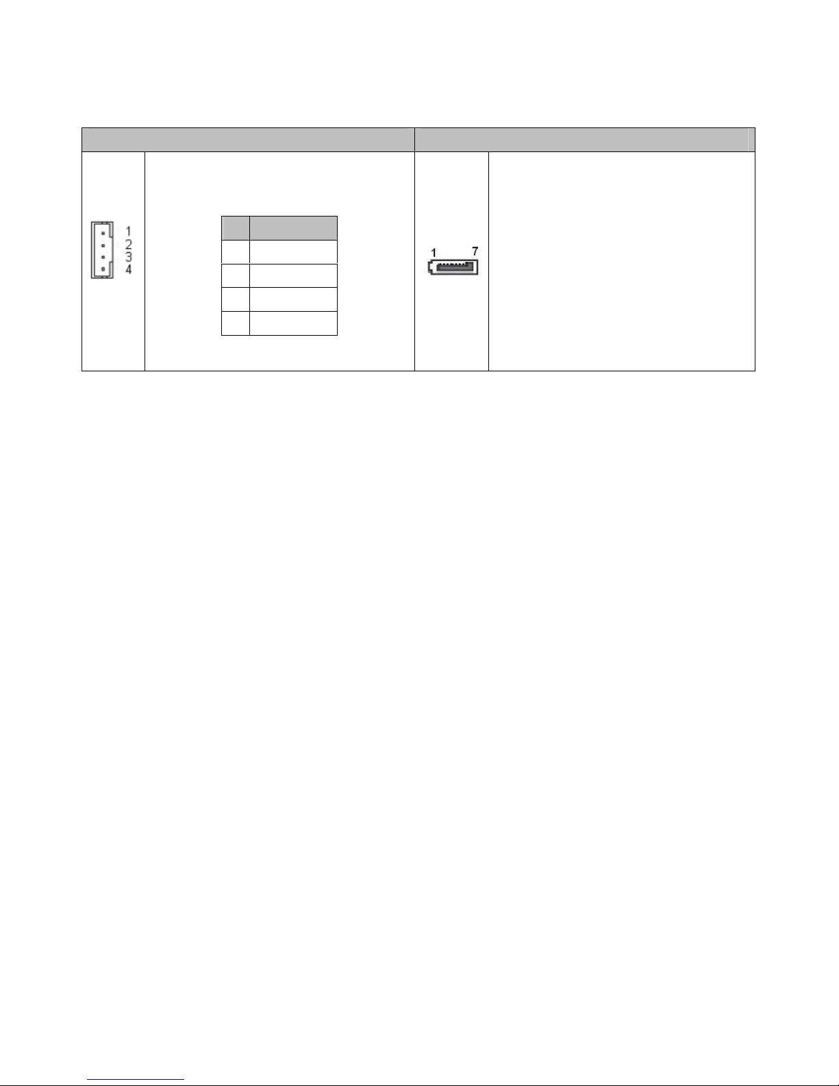
22. SATA_PWR1 23. SATA1 (SATA device connector #1)
SATA_PWR1 SATA Device Power Connector
PIN SIGNAL
1 +12V
2 GND
3 +3.3V
4 +5V
To connect SATA device:
1.Attach either end of the signal cable to the
SATAconnectoronmotherboard.
Attach the other end to the SATA device.
2. Attach the SATA power cable to the SATA
device and connect the other end
from the power supply.
14

24, 25. COM2, COM2_485 (For COM2
Function select) 26. SPI1 (BIOS Programmable HEADER.)
COM2: For RS-232 Function
COM2_485: For RS-422,RS-485
Function
Pin SIGNAL
1 DSR
2 DCD
3 RTS
4 SIN
5 CTS
6 SOUT
7 RI
8 DTR
9 NC
10 GND
Pin SIGNAL
1 NC
2 485_422_TX+
3 NC
4 485_422_TX-
5 422_RX2-
6 NC
7 422_RX2+
8 NC
9 NC
10 GND
PIN DEFINE PIN DEFINE
1 CS0 2 +3.3V
3 MISO 4 HOLD
5 WP 6 CLK
7 GND 8 MOSI
9 N.C 10 N.C
15

Chapter 3 BIOS Settings
This chapter describes the BIOS menu displays and explains how to perform common
tasks needed to get the system up and running. It also gives detailed explanation of the
elements found in each of the BIOS menus. The following topics are covered:
Main Setup
Advanced Chipset Setup
SuperIO Setup
Security Setup
Boot Setup
Exit Setup
16

3.1 Main Setup
Once you enter the Phoenix BIOS™ CMOS Setup Utility, the Main Menu will appear on the
screen. Use the arrow keys to highlight the item and then use the <Pg Up> <Pg Dn> keys to
select the value you want in each item.
Note: Listed at the bottom of the menu are the control keys. If you need any help with the item
fields, you can press the <F1> key, and it will display the relevant information.
Option Choice Description
System Date N/A Set the system date. Note that the ‘Day’ automatically
changes when you set the date
System Time N/A Set the system time.
Processor Type N/A This item displays the CPU Type
Processor Speed N/A This item displays the CPU Speed
L2 Cache Ram N/A This item displays the L2 ache memory size
17

Total Memory N/A This item displays the memory size that used.
System Memory Speed N/A This item displays the memory speed.
Memory Mode N/A This item displays the memory mode.
Memory Channel Slot 0 N/A This item displays the memory size that used On slot 0.
BIOS Version N/A This item displays BIOS’s Version
Build Time N/A This item displays the building time of BIOS.
18

3.2 Advanced Chipset Setup
Option Choice Description
Full Screen Logo
Show
Enabled
Disabled Displays the full screen logo upon BIOS booting
Quick Boot Enabled
Disabled
Allows the system to skip certain tests while booting. This
will decrease the time needed to boot the system.
Audio
Auto
Enable
Disable
Control detection of the Azalia device.
Lan Control Enabled
Disabled Control the Lan.
Boot Type
CRT
CRT+DVI
DVI
Select the Video Device activated during POST. When you
select CRT+DVI then DVI would be main output in DOS.
19

3.3 Superio Setup
20
Other manuals for AR-B6005
1
Table of contents
Other Acrosser Technology Automobile Accessories manuals

Acrosser Technology
Acrosser Technology AR-B1896 User manual

Acrosser Technology
Acrosser Technology AIV-QM97V1FL Series User manual

Acrosser Technology
Acrosser Technology AR-V6002FL User manual

Acrosser Technology
Acrosser Technology AIV-HM76V1FLCi3 User manual

Acrosser Technology
Acrosser Technology AIV-HM76V0FL Series User manual
Popular Automobile Accessories manuals by other brands


Kaiser Willys
Kaiser Willys Tigertop 51405 installation instructions

AMP Research
AMP Research Power Step installation guide

ARB
ARB Airlocker RD143 installation guide

Havis-Shields
Havis-Shields KK-S-120-6 Specification sheet

Cruz
Cruz E30-158 Assembly instructions

Buyers
Buyers LT19 Installation and operator's manual


