AMPTRON 3SLAV User manual

Copyright 2000 Publishing. All Rights Reserved.
This manual, software and firmware described in it are copyrighted by their respective owners
and protected under the laws of the Universal Copyright Convention. You may not reproduce,
transmit,transcribe,storeinaretrievalsystem,ortranslateintoanylanguage,inanyformorby
anymeans,electronic,mechanical,magnetic,optical,chemical,biological, molecular, manual,
orotherwise, any part ofthispublication without the expresswrittenpermission of the publisher.
All products and trade names described within are mentioned for identification purpose only.
No affiliation with or endorsement of the manufacturer is made or implied. Product names and
brands appearing in this manual are registered trademarks of their respective companies.
The information published herein has been checked for accuracy as of publishing time. No
representation or warranties regarding the fitness of this document for any use are made or
implied by the publisher. We reserve the right to revise this document or make changes in the
specificationsoftheproduct described therein at any time without notice and without obligation
to notify any person of such revision or change.
User Manual V1.0

2
3SLAV User’s Manual
Item Checklist
Before you begin installing your motherboard, please make
sure that the following materials have been shipped:
This mainboard comes in a sturdy cardboard shipping
carton, which should contain the following items:
• The main board.
• This user manual.
• One Floppy disk drive cable.
• One Ultra DMA/66 IDE cable.
• One Serial port cable.
• Software utilities.
If you discover damaged or missing items, please contact your
retailer.
User’s manual Version: 1.2
Release Date: May 2000

3
3SLAV User’s Manual
CONTENTS
Introduction ........................................................... 5
1-1 Introduction ......................................................................................5
1-2 Specifications ..................................................................................5
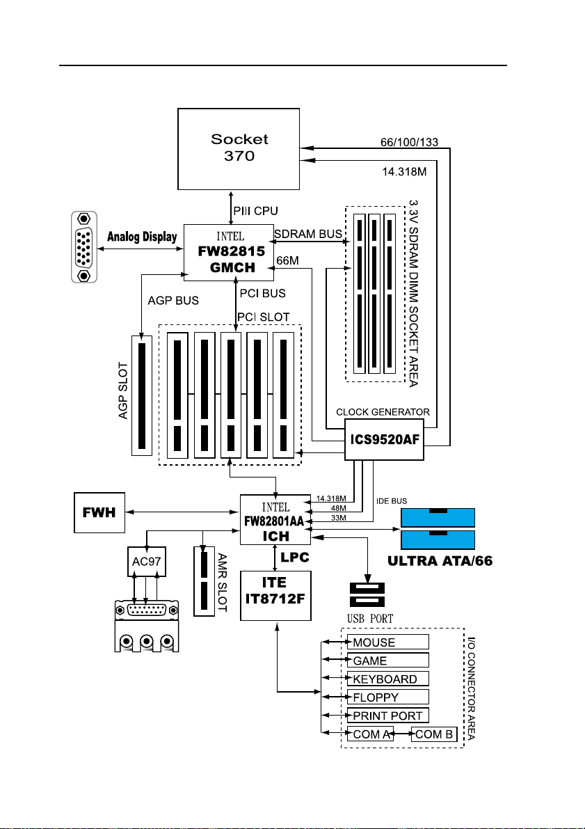
1-3 Block Diagram ..................................................................................8
1-4 Main Board Layout with Default Setting .............................................9
1-5 Static Electricity Precautions ..........................................................10
Installation Procedures ....................................... 11
2-1 Setting System Jumpers ................................................................ 11
2-2 System Memory (DIMM) .................................................................14
2-3 Central Processing Unit (CPU) ........................................................15
2-4 Expansion Cards.............................................................................15
2-5 External Connectors........................................................................16
2-6 Power Connection Procedures ........................................................23
AWARD BIOS Setup.......................................... 24
3-1Introduction .....................................................................................24
3-2 Main Menu ......................................................................................26
3-3 Standard CMOS Setup....................................................................28
3-4 Advanced BIOS Features ................................................................31
3-5 Advanced Chipset Features/Integrated Peripherals ..........................34
3-6Integrated Peripherals .....................................................................37
3-7 Power Management Setup. ............................................................. 41
3-8 PnP/PCI Configuration Setup...........................................................44
3-9 PC Health Status ............................................................................46
3-10 Frequency Control .........................................................................46

4
3SLAV User’s Manual
3-11 Defaults Menu ...............................................................................47
3-12 Password Setting ..........................................................................48
3-13 Exit Selecting................................................................................49
Software Driver Install......................................... 50
4-1UPDATEDPRODUCTINFORMATION .............................................50
4-2 Install Graphics Driver .....................................................................53
4-3 Install Audio Driver...........................................................................56
4-4 ALC100 ALSRACK Application .......................................................59
Anti-Virus software installation ............................ 63
5-1 Anti-Virus software installation ........................................................63

5
3SLAV User’s Manual
1-1 Introduction
The motherboard is a high-performance, low-cost motherboard which sup-
portstheIntelPIII FC-PGA andSocket370 microprocessor. Systemmemory
bank supports 3 DIMM socket. Memory up to 768MB 100MHZ & *133MHZ
SDRAM.
On-board include 4X AGP, ATX power, Super I/O, 2 Ultra DMA33/66 EIDE
interfaces, 2 USB ports, 1 4X AGP Expansion Slot,5 PCI Expansion slots,
and 1 AMR Slot.
1-2 Specifications
CPU - Pentium III®/CeleronTM Processor.
- Celeron TM Socket 370 PPGA packaged Processor.
- 2 nd level Cache Depend on CPU.
- Coppermine Socket 370 FCPGA packaged Processor.
- Support Up 1GHz Processor Cooling FAN Spec.
- VIA Cyrix Processor (Joshua)
Chipset - INTEL FW82815 Graphics and memory controller Hub(GMCH).
- INTEL FW82801AA I/O Controller Hub(ICH).
Clock Generator
- Supports 66 / 100 / 133 MHz FSB.
( "*" means frequency can be adjusted, and subject to different
configuration )
Memory - 3 x 168-pin DIMM Sockets.
- Supports 100MHZ & 133MHZ SDRAM 32MB~768MB.
- In- Supports only 3.3V SDRAM DIMM.
Introduction

6
3SLAV User’s Manual
VGA - Integrated 2D/3D graphics chip(GMCH).
- Integrated 24-bit 230MHz RAMDAC.
- Support 4MB max Display Cache at AIMM Card.
- 2D graphics Up 1600x1200 in 8-bit Color at 85 Hz Refresh.
-H/W MotionCompensation Assistancefor S/WMPEG2 Decode.
- Software DVD at 30fps.
Audio - Supports AC97 CODEC (Avance Logic ALC100).
- Supports earphones, two channel speaker mode.
- MPU-401 Game/MIDI port and Sound blaster®16 compatible.
- Avance Logic. Sound Effects Utility Support Four Surround
Mode and KaraOK Mode.
I/O Controller
- ITE 8712F Low Pin Count(LPC) interface.
Expansion Slot
- Five 32-bit PCI slots support Master mode.PCI Rev 2.2
Compliant.
- One AGP Slot support 1x 2x 4x Data Rate.
- One AMR Slot.
I/O Interface
- PCI Bus master IDE interface on board with two connectors
support 4 IDE devices in 2 channel, the PCI IDE Controller
supports PIO Mode 0 to Mode 4, Bus master IDE DMA Mode 2
and Ultra DMA 33/66.
- On board super Multi-I/O chip that support 2 serial port with
16550 Fast UART compatible, 1 parallel port with EPP and
ECP capabilities, and a floppy disk drive interface.
- On board support PS/2 mouse Connector.
- On board support PS/2 Keyboard Connector.
- On board 2 USB ports.
- On board IrDA connector.
- Floppy port supports 2 FDD with 360K, 720K,1.2M,1.44M and
2.88M bytes ,Supports LS-120 floppy disk device.

7
3SLAV User’s Manual
Other Function
- Support Modem Ring Power On.
- Supports Keyboard, and WOL (Wake On LAN).
- CPU Work Clock auto detection by BIOS.
Power Supply
- On board 3V, 5V and 12V 20-pin ATX power connector.
- Use switching regulator to support CPU core voltage.
- CPU Core voltage auto detection.
Hardware Monitor
- CPU/Power Supply/Chassis Fan Revolution detecting.
- CPU Fan Control.
- System Voltage Detect.
- Display Actual Current Voltage.
BIOS - Licensed AWARD BIOS, 4M bit Firmware Hub.
- ACPI ready for PC98/Windows 98.
-SystemBIOSsupportsACPI function andGreenfeaturefunction,
DMI, Plug and Play Flash ROM.
Form factor
- ATX Form Factor.
- Dimensions 305mm x 200mm, 4 layers PCB.
Drivers
- Intel®815 Chipset Graphics Drivers.
- INF Update Utilities.
- AC97 audio sound drivers.
- Virus Protection Applications.
- DirectX 7.0.

8
3SLAV User’s Manual
1-3 Block Diagram

9
3SLAV User’s Manual
1- Main Board Layout with Default Setting
System default support PIII(100/133MHz FSB) and Celeron
CPU

10
3SLAV User’s Manual
1-5 Static Electricity Precautions
Static electricity can easily damage your motherboard.
Observing a few basic precautions can help you safeguard against dam-
age that could result in expensive repairs. Follow the measures below to
protect your equipment from static discharge:
Keep the motherboard and other system components in their antistatic
packaging until you are ready to install them.
Touch a grounded surface before you remove any system component from
its protective antistatic packaging. A grounded surface within easy reach
is the expansion slot covers at the rear of the system case. or any other
unpainted portion of the system chassis.
During configuration and installation, touch a ground surface frequently to
discharge any static electric charge that may build up in your body. An-
other option is to wear a grounding wrist strap.
When handling a motherboard or an adapter card, avoid touching its
components.Handle the motherboardand adaptercards eitherby theedges
or by the mounting bracket that attaches to the slot opening in the case.

11
3SLAV User’s Manual
The mainboard has some user-adjustable jumpers on the board that allow
you to configure your system to suit your requirements. This chapter con-
tains information on the various jumper settings on your mainboard.
To set up your computer, you must complete the following steps:
1. Setting system jumpers.
2. Install RAM modules.
3. Install CPU & FAN.
4. Connect ribbon cables, cabinet wires, and power supply.
5. Set up BIOS.
6. Set up system drivers and utility.
2-1 Setting System Jumpers
You may configure your motherboard to match the needs of your applica-
tions by setting jumpers. A jumper is the simplest kind of electrical switch.
It consists of two metal pins and a small metal clip (often protected by a
plastic cover) that slides over the pins to connect them. To "close" a jumper,
you connect the pins with the clip. To "open" a jumper, you remove the
clip. Sometimes a jumper will have three pins, labeled 1, 2, 3. In this case
you would connect either pin 1 and 2 or 2 and 3.
The jumper settings are schematically depicted in this manual as follows:
A pair of needle-nose pliers may be helpful when working with jumpers.
Installation Procedures
OPEN CLOSED CLOSED 2-3
123

12
3SLAV User’s Manual
Note: When you open the jumper, attach the plastic jumper cap to one of
the pins so you won't lose it.
Warning: Always completely disconnect the power cord from your board
whenever you are working on it. Do not make connections while the power is
on because sensitive electronic components can be damaged by the sud-
den rush of power.
Always ground yourself to remove any static charge before touching the
board.Modemelectronic devicesare very sensitiveto staticelectric charges.
Use a grounding wrist strap at all times. Place all electronic components on
a static-dissipative surface or in a static-shielded bag when they are not in
the chassis.
CPU Type Settings:(JP1)
The Motherboard supports Intel PIII/Socket 370/FCPGA CPUs and Cyrix
(JOSHUA) CPUs. Setting the jumper according to the CPU type. you are
going to install on the motherboard.
123
123
States JP1
Support intel Serial
CPU
[Default]
Support VIA Cyrix
Serial
CPU Only.
[JOSHUA]
1
2

13
3SLAV User’s Manual
Clear CMOS:(JP7)
To clear the data stored in the CMOS, always turn off the computer first,
then remove this jumper to 2-3 pin to clear the CMOS. The jumper should
be set to 1-2 pin (3V battery back up) before turn on the computer.
Keyboard Power On Selection(JP2)
The keyboard power on selection function. If your ATX power supply can
supports 700mA 5V standby current (with keyboard require).you can use
this function.
1
2
3
1
2
3
If your ATX power supply not support
700mA 5V standby current.Don’t enable
this function.
States JP2
Enable this function
Disable [Default]
1
2
123
123
States JP7
Normal[Default]
Clear CMOS
1
2

14
3SLAV User’s Manual
2-2 System Memory (DIMM)
The motherboard supports up to 768MB 100/133MHz SDRAM. No hard-
wareor BIOS setupis requiredafteradding or removingthe systemmemory.
Note:
1. The motherboard uses only Dual Inline Memory Modules (DIMMs).
Sockets are available for 3.3Volt (power level) Synchronous Dynamic
Random Access Memory (SDRAM).
2. The 100/133 MHz compliant SDRAM must be used because of the
strict timing issues involved under this speed.
Installing system Memory
Insert the DIMM module(s) as shown. Because the number of pins are
different on each side of the breaks, the module will be fitted only in the
orientation shown. The DIMM must be 3.3V for this motherboard.

15
3SLAV User’s Manual
2-3 Central Processing Unit (CPU)
The Motherboard provides a ZIF Socket 370. The CPU that came with the
motherboard should have a fan attached to it to prevent overheating. If this
in not the case, then purchase a fan before you turn on your system. Be
sure that there is sufficient air circulation across the processor heat sink,
or the processor could overheat and damage both the processor and the
motherboard.
To install a CPU, first turn off your system and remove its cover. Locate the
ZIF socket and open it by first pulling the lever sideways away from the
socket then upwards to a 90-degree angle. Insert the CPU with the correct
orientation as shown. The notched corner should point towards the end of
the lever. Because the CPU has a corner pin for two of the four corners,
the CPU will only be fitted in the orientation as shown. The picture is for
reference only: you should have a CPU fan that covers the top side of the
CPU. With the added weight of the CPU fan, no force is required to insert
the CPU. Once completely inserted, close the socket’s lever while holding
down the CPU.
2- Expansion Cards
Always unplug the power supply when adding or removing expansion cards
or other system components. Failure to do so may cause severe damage
to both your motherboard and expansion cards.
Expansion Card Installation Procedure The Motherboard has 5 PCI Expan-
sion slots. You may install up to 5 PCI cards on this motherboard. To install
the PCI cards , please follow the following procedure:
1. Read the documentation for your expansion card and make any nec-
essary hardware or software settings for you expansion card, such as
jumpers or switches.
2. Remove your computer system cover and the bracket plate with screw
on the slot you intend to use. Keep the bracket for possible future use.
3. Carefully align the card connectors and press firmly.
4. Secure the card on the slot with the screw you removed above.
5. Replace the computer system cover.
6. Setup the BIOS if necessary.
7. Install the necessary software drivers for your expansion card.

16
3SLAV User’s Manual
2-5 External Connectors
1.PS/2 Mouse Connector:
The motherboard provides a mini-DIN mouse connector, which supports a
PS/2 style mouse.
2.PS/2 Keyboard Connector:
This connector is for a standard keyboard using a PS/2 plug (mini DIN). This
connector will not allow standard AT (large DIN) keyboard plugs. You may
use a DIN to mini DIN adapter on standard AT keyboards. In some
applications, the keyboard is not present, the standard BIOS will report an
error or failure during the Power-On Self Test (POST) after resetting the PC.
You may select "All, But Keyboard" under the "Halt On" in "Standard CMOS
SETUP" of BIOS SETUP.
This allows the system non-keyboard operation without the system halting
during the POST.
3.Universal Serial BUS (USB) Ports 1 & 2:
There are two USB ports on this motherboard for connecting USB devices.

17
3SLAV User’s Manual
4.Parallel Port Connector:
Normally, the parallel port is used to connect the system to a printer.
5.Serial Port COM1 connector:
The COM1 port is ready for a mouse or other serial devices. A second serial
port is available using a serial port bracket connected from the motherboard
to an expansion slot opening.
6.Display connector:
This connector is for output to a VGA-compatible device, commonly used
for conventional CRT displays.

18
3SLAV User’s Manual
7.Floppy Disk Drive Connector(FDC)
You can attach up to two floppy drives to the motherboard. After connecting
the single end to the board, connect the two plugs on the other end to the
floppy drives. The drive A: should be connected on the end and the drive B:
in the middle.
Note: Pin 5 is removed to prevent the users inserting the Floppy Disk Drive
in the wrong orientation when using ribbon cables with pin 5 plugged.
8.Primary/Secondary IDE Connectors(IDE1 and IDE2)
Floppy Disk Drive
Connector
Color: White
Note: Orient the red marking on the floppy
ribbon cable to pin1
Primary IDE Con-
nectors
Color:Blue
Secondary IDE
Connectors
Color:Withe

19
3SLAV User’s Manual
Themotherboardsupportsup tofureIDE devices,includingCD-ROM drives,
tape backup drives, Hard Disk Drives, and other IDE devices. After connect-
ing the single end to the board, connect the two plugs at the other end to
your hard disk(s). If you install two hard disks, you must configure the sec-
ond drive to Slave mode by setting its jumper accordingly. Please refer to
your hard disk documentation for the jumper settings. (Pin 20 is removed to
prevent the users inserting the IDE devices in the wrong orientation when
using ribbon cables with pin 20 plugged).
Note: Ultra DMA/66 IDE devices must use an 80-wire IDE cable or else
devices will automatically be limited to Ultra DMA/33 mode.
9.Wake-On-LAN(WOL)connectors(J2)
The Wake-On-LAN connectors connect to a LAN card respectively with a
Wake-On-LANoutput. Theconnectors powerup the systemwhen a wakeup
packet or signal is received through the LAN card.
Wake-On-Lan(WOL)connectors
PIN
FUNCTION

20
3SLAV User’s Manual
10.CPU/Chassis Fan Connectors(FAN1 and FAN2 and FAN3)
This motherboard provides CPU, Power, and Chassis fan connectors. Ori-
entatethe fansothat theheat sink finsallow airflowto goacross theonboard
heat sink(s) instead of the expansion slots. Depending on the fan
manufacturer, the wiring and plug may be different. The red wire should be
positive, while the black should be ground. Connect the fan plug to the board
taking into consideration the polarity of the connector.
Note: The CPU and motherboard will overheat if there is no airflow across
the CPU and onboard heatsink. Damage may occur to the motherboard and
the CPU fan if these pins are incorrectly used. These are not jumpers, do
not place jumper caps over these pins.
1 SENSOR
2+12V
3 GND
1
2
3
SENSOR
+12V
GND
1 SENSOR
2+12V
3 GND
CPU FAN
OTHERFAN
AGP FAN
Table of contents
Other AMPTRON Motherboard manuals

AMPTRON
AMPTRON M935 Series User manual

AMPTRON
AMPTRON 3WMV Series User manual

AMPTRON
AMPTRON M810D Series User manual

AMPTRON
AMPTRON PM-9800 User manual

AMPTRON
AMPTRON PM8400B User manual

AMPTRON
AMPTRON M585LMR User manual

AMPTRON
AMPTRON PII-3100 User manual

AMPTRON
AMPTRON M817 Series User manual

AMPTRON
AMPTRON 3IBAT User manual

AMPTRON
AMPTRON M810LR User manual