14 15
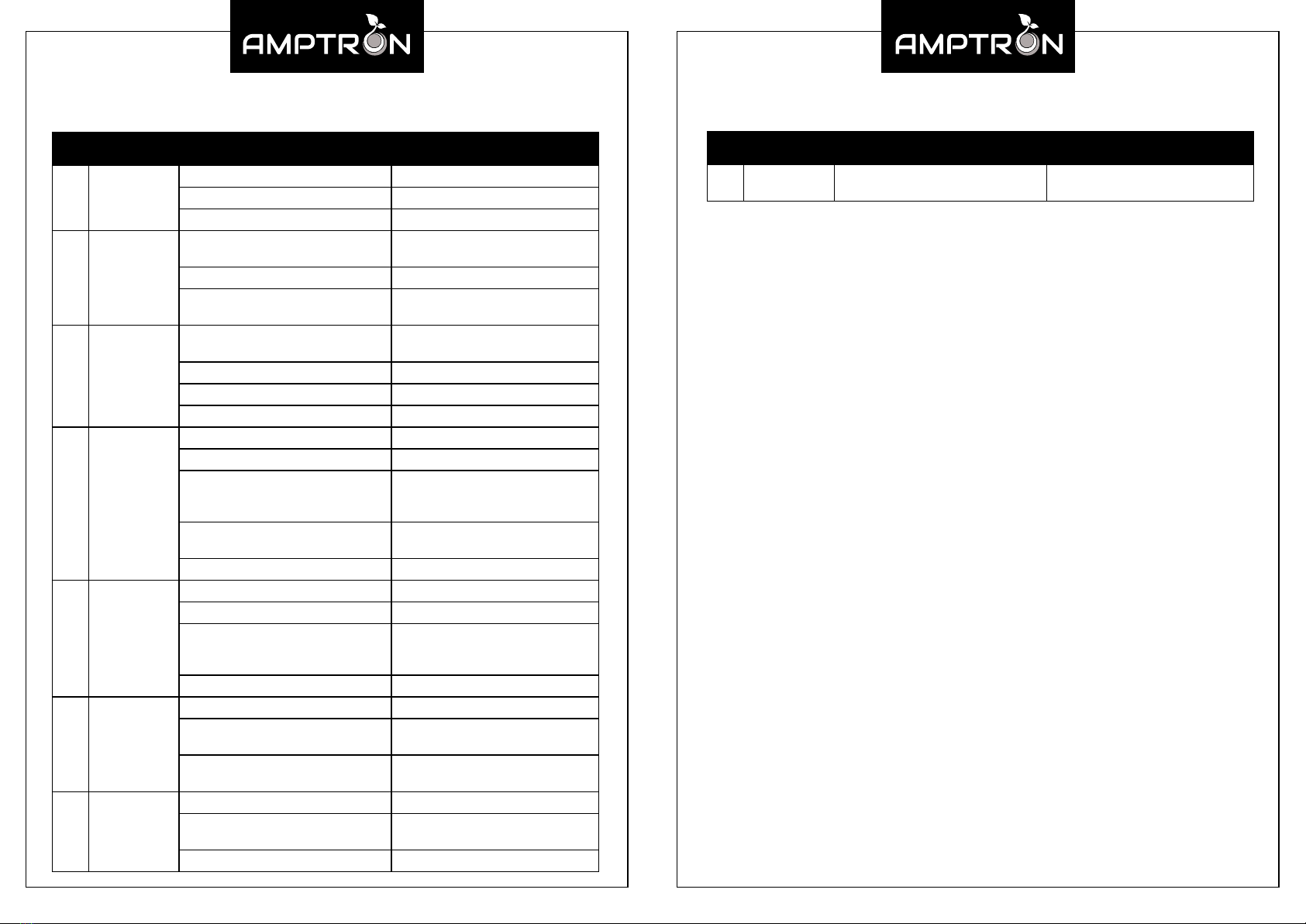
No. Fault Status Emergent Reasons Cause Analysis / Solution
1 Cannot boot
Under voltage protection Charge
Load exception protection Disconnect the load and charge
Product damage Repair
2Charger not
charging
Charge over current protection Use a charger that complies with
product specications
The charger is damaged Replace the charger
Charger is not working properly Charger power supply error or
connection abnormality
3Solar panels
cannot charge
Charge over current protection Using solar panels that meet product
specications
The charge current is too low Insucient sunlight
Solar panels damaged Replacement of solar panels
Solar panel connection damaged Replace or repair wire harness
4 No DC output
Battery under voltage protection Charge
Discharge over current protection Equipment power draw is too high
Over temperature protection
Check that the cooling fan is
operational and unobstructed.
Relocate to a cooler environment.
Harness quality is poor, harness
voltage drop. Use better quality wiring harness
Product damage Repair
5 No AC output
Battery under voltage protection Charge
Discharge over current protection Equipment power draw is too high
Over temperature protection
Check that the cooling fan is
operational and unobstructed.
Relocate to a cooler environment.
Product damage Repair
6Icon
constantly On
Load exception Disconnect the load
Corresponding hardware failure To replace the corresponding
hardware
The display is damaged To replace the corresponding
hardware
7Icon Exception
O
Load exception Disconnect the load
Corresponding hardware failure To replace the corresponding
hardware
The display is damaged Repair
Fault Resolution
No. Fault Status Emergent Reasons Cause Analysis / Solution
8Display does
not light up The display is damaged Repair
Note: If the above table does resolve the problem, please contact us.
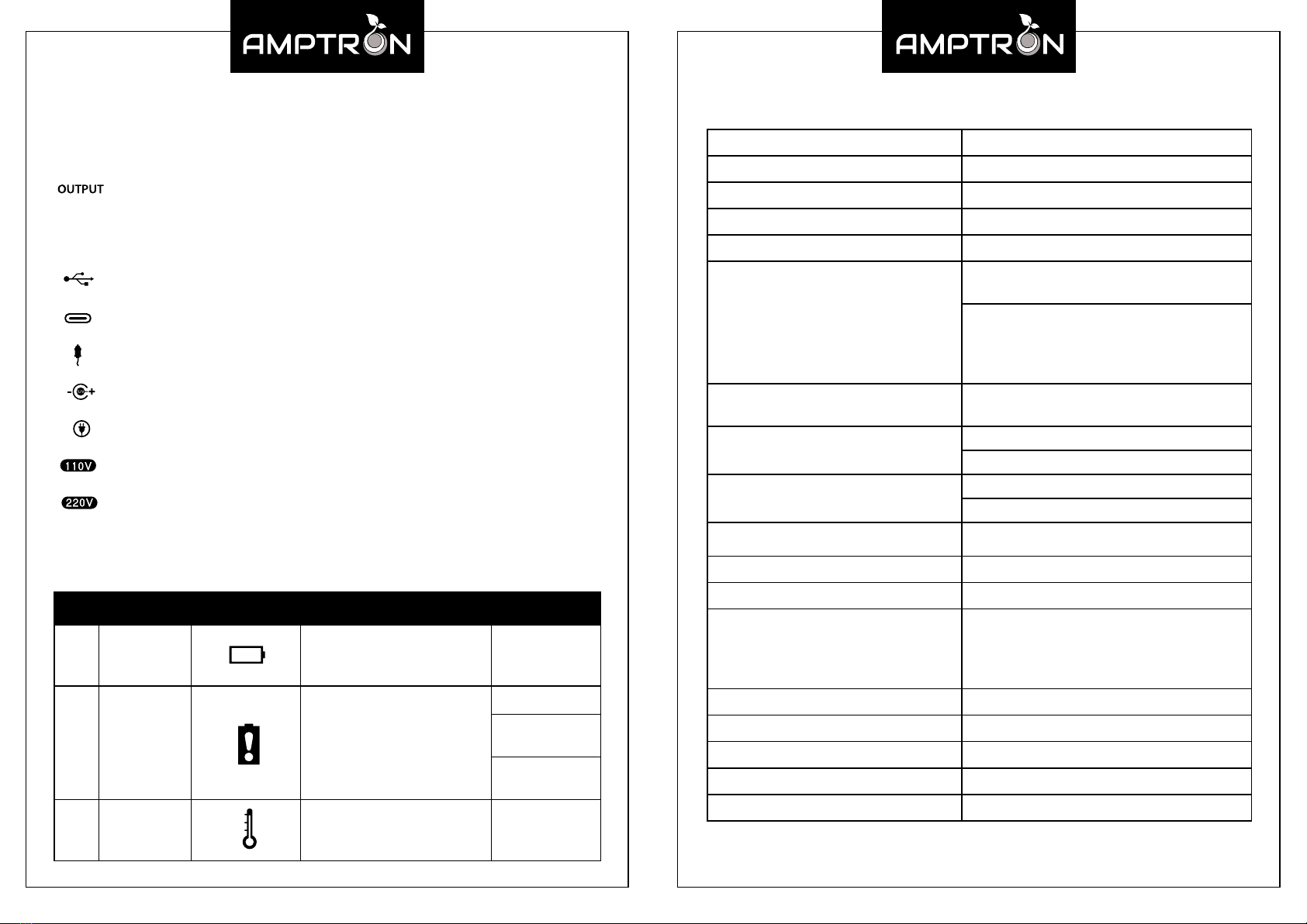
Environmental Conditions
• The product should only be used in a dry, clean and ventilated environment.
• Avoid exposure to direct sunlight, rain, moisture, dust, acid mist environments.
• Never use the P750 in a ammable or explosive gas environment due to the
possibility of sparks!
• Ensure ambient temperature is in the range of -10oC to 55oC.
• Ensure air humidity is no more than 80% (25oC ± 5 oC).
After-Sales Service
• Warranty Cover:
Your P750 Portable Power Pack comes with a 2-year warranty, which starts from the
date of purchase. If you lose your receipt, the 2-year warranty will be based on the
battery code. Warranty covers failure due to defects in material or workmanship.
Subject to any issues stated below AMPTRON® will repair or replace the P750
portable power pack and/or parts of the battery if components in question are
defective in materials or workmanship.
• Warranty Procedure:
The defective Portable Power Pack must be returned to our lab to determine the
cause of the failure and if it is repairable. If it was damage caused by a
manufacturers defect, it will be repaired or replaced at no cost to you.
• Not Covered By Warranty:
Warranty will not honor defects caused by abuse/neglect or from items outside the
manufacturers control. Please visit our website to see the full warranty breakdown:
www.amptron.com.au/warranty---p750-power-pack.html
• Disclaimer:
Customers must adhere to all AMPTRON® documentations and guidelines.
The manufacture is not responsible for any expenses related to installation or
removal, electrical system tests, battery charging, loss of time or other expenses
which should be considered incidental damages, including all shipping charges
after the rst 30 days of warranty.