AMS MFA 1001 User manual

User Manual
MFA 1001
Universal Multifunction Meter
________________________________________________________________________________
Automatische Mess- und
Steuerungstechnik GmbH
91275 Auerbach • Enge Gasse 1 Phone +49 (0) 96 43 / 92 05 - 0 Internet: www.ams-messtechnik.de
91270 Auerbach • Postfach 1180 Telefax +49 (0) 96 43 / 92 05 - 90 e-mail: [email protected]
________________________________________________________________________
Subject to technical changes UM 800.01 Rev.: 19.07.2006

2
Table of contents page
1 Product description ........................................................................ 3
1.1 Application.......................................................................................... 3
1.2 Working principle ............................................................................... 3
1.3 Calibration ......................................................................................... 3
2 Installation and Starting up ............................................................ 3
2.1 Installation notes ................................................................................ 3
2.2 Inputs, outputs and interfaces............................................................ 4
2.3 Possible connections ........................................................................ 5
3 Operation ......................................................................................... 5
3.1 Controls ............................................................................................. 5
3.2 Display layouts .................................................................................. 6
3.3 Additional display .............................................................................. 7
4 Setup ................................................................................................ 7
4.1 General notes .................................................................................... 7
4.2 Possible parameters and factory presets .......................................... 8
4.3 Setting the voltage transformer translation ratio ............................... 8
4.4 Setting the current transformer translation ratio ................................ 9
4.5 Setting the integration time (bimetal function).................................... 9
4.6 Setting the switched output (optional)................................................ 10
4.7 Deleting and resetting ....................................................................... 13
4.8 Setting the password ......................................................................... 14
5 Terminal configuration ................................................................... 15
6 Technical details ............................................................................. 16
7 Dimension drawing ......................................................................... 18
8 Maintenance .................................................................................... 18
9 Product service ............................................................................... 18

3
1 Product description
1.1 Application
The multifunction meter MFA 1001 is an electronic universal measuring device for measuring and
monitoring all the important parameters in a three-phase supply network with a centre tap
connection. The MFA 1001 is designed for fixed installation and registers voltages, currents,
frequencies and phase shift. It then calculates the active power and reactive power as well as the
power factor for each phase and for the entire network. Furthermore active energy is being
displayed for the entire network. An operating time counter is included.
A switched output is optionally available. A limit value can be defined for each network parameter
(LIMIT 1) which triggers an alarm if any reading is either exceeding or falling below the specified
programmed parameters. Output is triggered via a switching transistor. The alarm output can also
be configured as impulse output then sending a chain of impulses. The impulse ratio is proportional
to the active energy.
On request the MFA 1001 can be equipped with a separate input to connect an auxiliary power
supply (230 V AC).
1.2 Working principle
The MFA 1001 is based on a highly integrated measuring system employing a very modern
manufacturing process. All voltages and currents are being fed directly into the system, which
detects all network parameters. A high-performance micro processor then utilizes the data to
accurately display the active values using the calibration settings stored in its flash memory.
1.3 Calibration
The MFA 1001 leaves the production line ready calibrated. All details concerning accuracy apply
only to the product itself and exclude phase faults generated by any upstream current transformers
that might be connected.
2 Installation and starting up
2.1 Installation notes
The multifunction meter is designed for the fixed installation in low voltage systems. The device
may be mounted in any position.
The installation of the MFA 1001 must be carried out by a qualified technician. The legal
regulations applying to a specific application have to be taken into account by the qualified
technician.
Switchboard installation:
Metal switchboards or switchboard doors must be earthed.
Before connecting the MFA 1001 make sure that the condition of the local network corresponds
to the information supplied on the identification plate.
The device does not have its own power on/off-switch. Therefore, when mounting the device the
following must be observed:
- a switch must be installed with the power supply
- the switch must be fitted near the device for easy reach
- the switch must be labelled as being the separator switch for the device

4
Connections:
All connections of the MFA 1001 are situated on the back of the casing. The block terminals
are using screws to ensure safe and reliable connectionswith the network.
For your attention !
■Voltages above the permitted voltage range can destroy the device!
■Any current transformer terminals that are not earthed, might be dangerous when touched!
■Secondary current transformers that are not under load can hold voltages high enough to be
dangerous when touched and should therefore be short-circuited!
2.2 Inputs, outputs and interfaces
Voltage input:
It is possible to measure phase voltages of up to 475 V in a three-phase network without using
external transformers.
Available designs:
Measuring range, without auxiliary power:
340 ... 400 ... 475 V AC, L-L (196 ... 230 ... 275 V AC, L-N)
Mesuring range, with auxiliary power:
40 ... 400 ... 475 V AC, L-L (23 ... 230 ... 275 V AC, L-N)
All voltage inputs must be connected through lines protected by a fuse (2-6 A).
Current input:
The current inputs are not galvanically separated within the device. Current transformers must be
used for measuring currents. Their primary and secondary current values can be programmed
enabling the current values to be directly displayed.
Two measuring ranges are programmable:
Measuring range 1
Measuring range 2
0.05 ... 5 ... 6 A
0.05 ... 1 ...1.2 A
For your attention !
■If the current transformers are being earthed at the secondary end the connection must be made
on terminals “l” to ensure correct functioning of the device!
■If any of the current display shows “-“ the respective current direction is wrong. In that case the
terminals “k” and “l” must be checked and the polarity should be reversed if necessary.
Auxiliary power:
With the standard option the auxiliary power needed to operate the MFA 1001 is supplied via the
Phase L1. Optionally the system is available with a separate auxiliary power input for a voltage of
230 V AC.
Attention has to be paid to making the correct connections.
Switched limit value / impulse output (optional):
From each of the measured or calculated network parameters limit values can be monitored.
These limit values can be assigned to the switched output.
The limit value output can optionally be set as impulse outputs. Then a chain of impulses with the
impulse ratio being proportional to the active energy is sent to the output.

5
2.3 Possible connections
3. Operation
3.1 Controls
The multifunction meter is operated by 4 control keys:

6
When in display mode the 4 keys serve as hotkeys to activate pre-programmed display
combinations. When in setup mode the keys are used to select the desired menus or program the
device.
Key T2( ↓) moves the display mode of the three main displays up one position, the key T1 ( ↑)
moves down one position. Key T3 ( OPT ) selects the options of a specific display combination.
Key T4 ( EIN ) selects the display mode of the 8-digit additional display layouts (operating time
counter, active energy or ‘no display’).
3.2 Display layouts
The following table shows the display layout presets:
______________________________________________________________________________
Display Option Display Description
selection
T2 (↓) T3 (OPT)
______________________________________________________________________________
1 U L1-N Present voltage phase-zero
UL2-N
U L3-N
2 U L1-L2 Present voltage phase-phase
U L2-L3
U L3-L1
3 1 I L1 Present current
I L2
I L3
2 I L1 mean Average current in relation to
I L2 mean the programmed integration time
I L3 mean
3 I L1 max Maximum current (measured)
I L2 max since last reset
I L3 max
4 I L1 mean max Maximum current (average)
I L2 mean max since last reset
I L3 mean max
4 f L1 Mains frequency of the displayed phase
f L2
f L3
5 P L1 Present value of active power
P L2
P L3
6 Q L1 Present value of reactive power
Q L2
Q L3
7 cos φL1 Power factor
cos φL2
cos φL3
8P sum Total active power (L1, L2, L3)
Q sum Total reactive power (L1, L2, L3)
cos φsum Power factor of the entire network (L1, L2, L3)

7
3.3 Additional display
The additional displays can be accessed via the T4 (EIN) key.
The additional parameters displayed are: operating time in h and received active energy in Wh,
kWh or MWh.
Display parameters of the additional display:
_________________________________________________________
Display Display Description
selection
T4 (EIN)
_________________________________________________________
1 h operating time
2 Wh active energy, received
3display OFF
4. Setup
4.1 General notes
When using the multifunction meter for the first time in a specific environment the MFA 1001 needs
to be adapted to the attached periphery using the setup mode.
To activate setup mode press both the T1 and T2 key simultaneously for at least 3 seconds.
The MFA 1001 always starts in setup mode with the setup option
►Setup of the voltage transformer translation ratio („V, V, ADJUST“)
The T2 ( ↓) key can be used to proceed through the selection in the following order:
►Setup of the current transformer translation ratio („A, A, ADJUST“)
►Selection of the integration time to calculate average values („sec“)
►Selection of all criteria for switched output („LIMIT 1 ADJUST“), optional
►Delete and reset functions („LOE ADJUST“)
►Password („PAS ADJUST“)
The displayed setup option is activated by pressing the T3 (OPT).
Press the T3 (OPT) key again to exit the setup menu.
It is possible to exit setup mode at any point by pressing the T4 key.
Any changes made up to that point are saved.

8
4.2 Possible parameters and factory presets
Description Adjustment range Factory presets
Primary voltage transformer
Identification plate, 400 V AC 1 V ... 999 kV 400 V
Secondary voltage transformer
Identification plate, 400 V AC 400 V (fixed setting) 400 V
Primary current transformer
Identification plate, 5 A / 1 A 1 A ... 999 kA 5 A
Secondary current transformer
Identification plate, 5 A / 1 A 1 A, 5 A 5 A
Integration time 5; 10; ... 480; 900 sec 900 sec
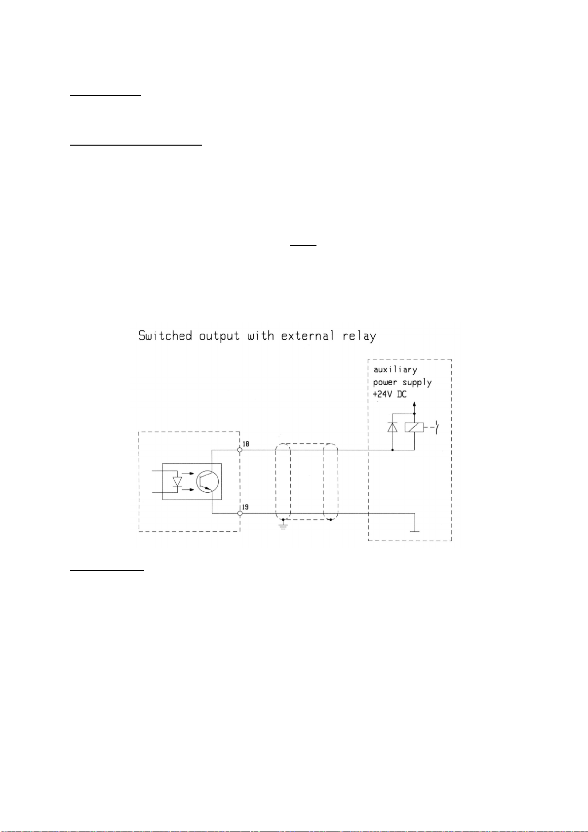
Switching output (LIMIT 1), (optional)
Measured value U, I, f, P, Q, cos φ,
Psum, Qsum, cos φsum,Wh, h,
Channel L1-N, L2-N, L3-N, L1-L2, L2-L3, L3-L1
Response time 0 ... 60 sec
Limit value freely programmable
Alarm type min, max
Deactivation „AUS“
Impulse output (optional)
Energy type active energy Wh active energy Wh
Energy flow direction received received
Impulse rate 1Wh ... 999 kWh / Impulse 100 Wh / Impulse
Delete functions Imax, Imean max, h, Wh, ALL
User password 000 ... 999 „000“ = no password
4.3 Setting the voltage transformer translation ratio
General notes:
The factory setting for the voltage transformer translation ratio is set to 400/400 V.
The preset voltage transformer translation ratio must be changed only if a voltage transformer is
used.
Setup:
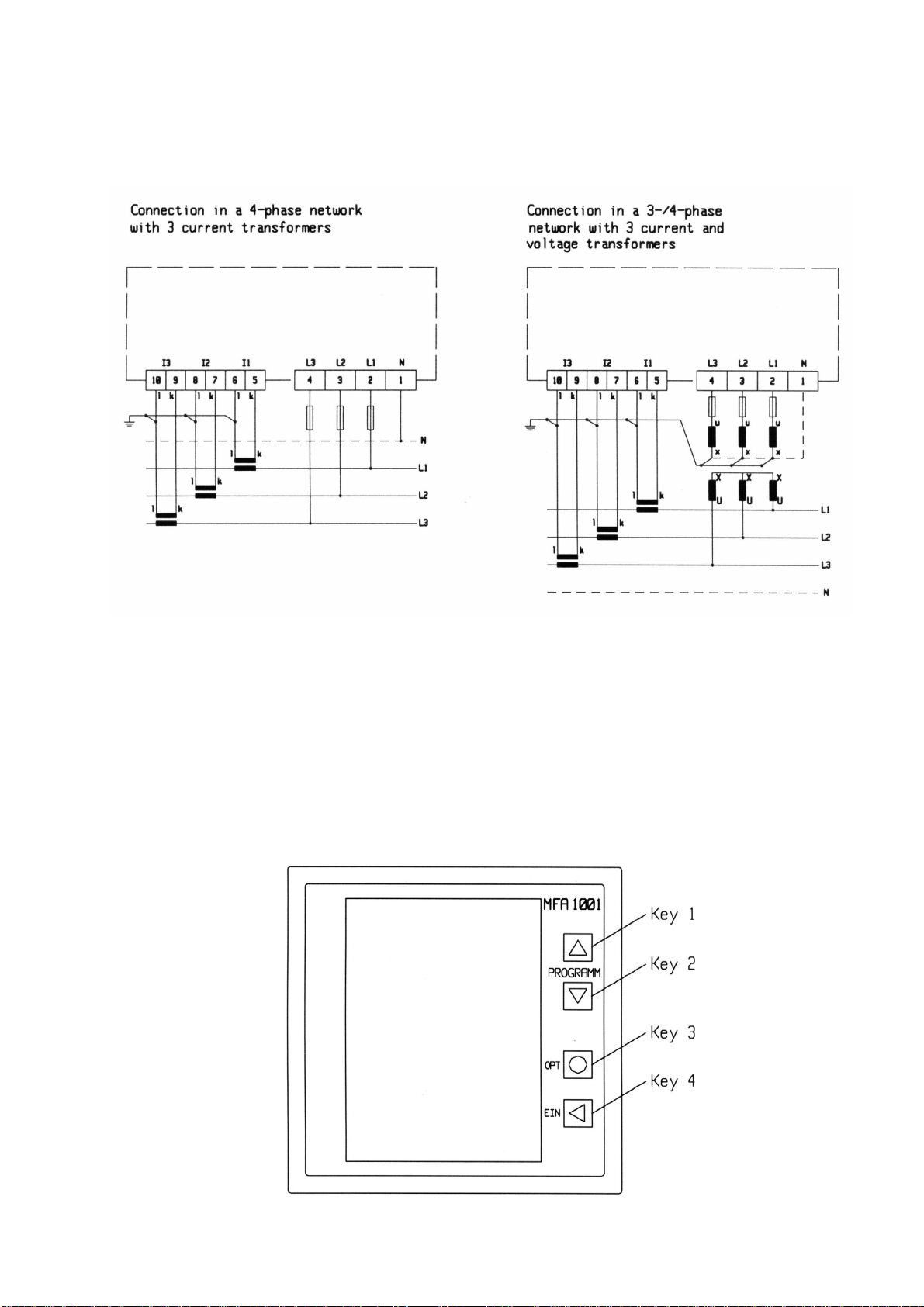
In order to change the displayed setup option („V, V, ADJUST“) press the T3 (OPT) key.
The preset setting „400V, 400V“ (1:1) is displayed with the first digit of the primary value flashing.
With the T1 ( ↑) key the value can be increased starting at “0” through to “9”. To access a lower
value press the T1 ( ↑) key past “9” to start again with “0”.
Press the T2 ( ↓) key to access the next digit. The digit starts flashing. To change the value press
T1 ( ↑) key.

9
After setting the last digit the decimal point starts flashing and can now be moved by pressing the
T1 ( ↑) key. For primary voltages above 1 kV the display can be changed over from “V” to “kV”. As
a result the primary voltage can be set to a minimum value of 1 V and a maximum value of 999 kV.
By pressing the T2 ( ↓) key the complete process of setting the primary voltage can be repeated.
The secondary voltage is set to 400 V ex factory and can not be changed.
The process is completed by pressing T3 (OPT) key. The setup menu is displayed.
4.4 Setting the current transformer translation ratio
General notes:
Only current transformers with a secondary value of 1 A or 5 A can be connected to the MFA 1001.
The setup menu is used to select the type of current transformer (primary and secondary current)
in use.
Setup:
Proceed to setting the current transformer parameters („A, A, ADJUST“) by pressing the T2 ( ↓)
key. Activate the selection by pressing the T3 (OPT) key.
The value “5A, 5A” (1:1) is displayed with the first digit of the primary value flashing. By using the
T1 ( ↑) key the value can be increased starting at “0” through to “9”. To access a lower value press
the T1 ( ↑) key past “9” to start again with “0”.
Press the T2 ( ↓) key to access the next digit. The digit starts flashing. To change the value press
T1 ( ↑) key.
After setting the last digit the decimal point starts flashing and can now be moved by pressing the
T1 ( ↑) key. For primary currents above 1 kA the display can be changed over from “A” to “kA”. As
a result the primary current can be set to a minimum value of 1 A and a maximum value of 999 kA.
By pressing the T2 ( ↓) key the setting for the primary current is stored and the menu for selecting
the secondary current is displayed. By pressing the T1 ( ↑) key values of 1 A or 5 A can be
selected.
By pressing the T2 ( ↓) key the complete process of setting the primary and secondary currents
can be repeated.
The process is completed by pressing T3 (OPT) key. The setup menu is displayed.
4.5 Setting the integration time (bimetal function)
General notes:
An average value is calculated using the measured values for current. A shared value for the time
interval used for the calculation can be set.
Factory preset: 900 seconds
Setup:
Activate the setup menu by pressing the T3 key (OPT).
By pressing either the T1 ( ↑) or T2 ( ↓) keys a value {5; 10; 30; 60; 300; 480; 900 sec} can be
selected from the list of available values.
Exit by pressing T3 (OPT).

10
4.6 Setting the switched output (optional)
General notes:
The MFA 1001 is shipped with a switched output as an optional extra. The output can optionally be
used as a switched limit value output or as an impulse output.
Switched limit value output:
A limit value (LIMIT 1) can be defined for each network parameter which lead to the triggering of
the alarm signal if the measured value either exceeds or falls below the set limit (depending on the
setting).
The status of the switched output is indicated by the symbol “LIMIT 1” on the LC screen.
If any value is set for the switched output this symbol appears in the display in the corresponding
display window, like e.g. 3x voltage L-N.
If the threshold monitoring responds and an alarm is triggered, the corresponding display starts
flashing. The flashing symbol now appears in every display window in order to ensure that
exceeding the voltage limit is also indicated in other display windows (e.g. 3x current).
Connection example:
Impulse output:
If the switched output is programmed to function as an impulse output a chain of impulses with an
impulse ratio proportional to the active energy is transmitted to the output.
An impulse valency (Wh / impulse) can be assigned to the impulse output. The system calculates
an optimum time period to then collect the impulses within this time period and transmits them
with an impulse length of 75 ms to the output. The maximum frequency is 6.5 Hz. The impulse
intervals are variable depending on the output frequency and are not proportional to the power.
If the measured active energy exceeds the set impulse valency and therefore the maximum
frequency for the impulse output is exceeded, the remaining impulses are stored temporarily and
sent to the output later.
The active energy counter uses a reflux lock to ensure that impulses are only transmitted when
electric energy is received.

11
Connection example:
Switched output setup:
1. Press the T3 (OPT) key to activate the setup mode („LIMIT 1 ADJUST“).
2. Press the T1 ( ↑) or T2 ( ↓) keys to set the parameters to be monitored.
The following parameters can be selected:
Voltage U „V“
Current I „A“
Frequency f „Hz“
Active power P, received „W“
Reactive power Q, inductive „var“
Power factor, inductive /value/ „cos φ“
Accumulated values „sum“ T3→Accumulated active power „W sum“
Accumulated reactive power „var sum“
Power factor entire network „cos φsum“
Active energy „Wh“
Operating time „h“
Additional options:
Impulse counter function „PUL“ see below ‚Setup as impulse output’
Deactivation „AUS“ see below ‚Deactivating the limit output’
After the selection has been made press the T3 (OPT) key to proceed to the next step.
3. Press the T1 ( ↑) or T2 ( ↓) keys to select the phase (channel) of the network parameter to be
monitored.
The following options are available:
for voltage L1-N
L2-N
L3-N
L1-L2
L2-L3
L3-L1

12
for current, frequency, power, power factor L1
L2
L3
for accumulated active power, accumulated reactive no selection (phase-independent)
power, power factor entire network, active energy,
operating time
After the selection has been made press the T3 (OPT) key to proceed to the next step.
4. Setting the response time. The response time is the time interval during which the limit value is
exceeded (resp. fallen below) in order to trigger an alarm.
Use the T1 ( ↑) or T2 ( ↓) keys to set the response time.
Adjustment range: 0....60 seconds
After the response time has been selected press the T3 (OPT) key to proceed to the next step.
The response time also applies if the switched output is reset because the programmed value has
been fallen below (resp. exceeded).
5. Setting the response value. A preset value relevant to the selection of parameters and phases
is displayed with the first digit flashing.
With the T1 ( ↑) key the value can be increased starting at “0” through to “9”. To access a lower
value press the T1 ( ↑) key past “9” to start again with “0”.
Press the T2 ( ↓) key to access the next digit. The digit starts flashing. To change the value press
T1 ( ↑) key.
After setting the last digit the decimal point starts flashing and can now be moved by pressing the
T1 ( ↑) key. Also the measuring range “k” can be selected or changed to “M” where required.
6. Press the T2 ( ↓) key again and the “min” display starts flashing.
„min“: Alarm is triggered when falling below the set value
„max“: Alarm is triggered when exceeding the set value
Press the T1 ( ↑) key to select „min“ or „max“.
By pressing the T2 ( ↓) key the complete process of setting response value can be repeated.
The process is completed by pressing T3 (OPT) key. The setup menu is displayed.
Setup as impulse output:
The impulse valancy specified in Wh/impulse or kWh/impulse.
Impulse valancy = energy per impulse
Due to technical reasons the denomination “Wh” appears at the bottom of the display. If the range “kWh” is selected the
“k” apears apart from the “Wh” right hand from the impulse valency to be set.
1. Select and activate the impulse counter function (see 2. above) by pressing T3 (OPT).
2. Setting the impulse rate. A preset value relevant to the impulse rate is displayed with the first
digit flashing.
With the T1 ( ↑) key the value can be increased starting at “0” through to “9”. To access a lower
value press the T1 ( ↑) key past “9” to start again with “0”.

13
Press the T2 ( ↓) key to access the next digit. The digit starts flashing. To change the value press
T1 ( ↑) key.
After setting the last digit the decimal point starts flashing and can now be moved by pressing the
T1 ( ↑) key. Also the measuring range “k” can be selected where required.
The process is completed by pressing T3 (OPT) key. The setup menu is displayed.
Deactivating the switched output
The switched output can also be deactivated.
1. Select deactivation and activation of the switched output (see 2. above) by pressing T3 (OPT).
2. LIMIT 1 AUS ADJUST
is displayed with “AUS” flashing.
3. By pressing T3 (OPT) key the switched output is deactivated and the setup menu is displayed.
For your attention !
■For the switched output the latest set values for LIMIT 1 are used. For better support we
recommend to keep written protocol about settings and changes!
4.7 Deleting and resetting
General notes:
The following values stored by the MFA 1001 can be deleted:
Description Display Memory Type
_____________________________________________________________________________
Maximum measured current Imax max A
Maximum average current Imean max mean max A
Operating time h flash
Active energy Wh flash
Delete all
The parameters seen above can be deleted individually.
There is also the possibility to delete or reset all parameters together at the same time.
Deleting individual parameters:
1. Press the T3 (OPT) key to activate the setup mode („LOE ADJUST“).
2. Press the T1 ( ↑) or T2 ( ↓) keys to navigate within the menu (see table above).
3. Activate the desired option by pressing T3 (OPT)
Press the T1 ( ↑) or T2 ( ↓) keys to select further phase dependent parameters
4. Confirm the parameter to be deleted by pressing the T3 (OPT) key.
HAL appears flashing in the display.
Use the T1 ( ↑) or T2 ( ↓) keys to change from HAL to LOE.
HAL: delete nothing (hold)
LOE: delete
5. Press T3 (OPT) again.
The selected command is executed.

14
The selection menu LOE ADJUST is displayed.
6. Repeat the process to delete any other individual parameters by pressing T3 (OPT) key.
Use the T1 ( ↑) or T2 ( ↓) keys to proceed to the next option within the selection menu.
Deleting all parameters:
1. Press the T3 (OPT) key to activate the setup mode („LOE ADJUST“).
2. Press the T1 ( ↑) or T2 ( ↓) keys until “LOE” and “All” is displayed flashing alternately.
3. Press the T3 (OPT) key
Display ALL
HAL flashing
Use the T1 ( ↑) or T2 ( ↓) keys to change from HAL to LOE.
HAL: delete nothing (hold)
LOE: delete
4. Press T3 (OPT) again.
The selected command is executed
The selection menu LOE ADJUST is displayed.
5. Use the T1 ( ↑) or T2 ( ↓) keys to proceed to the next option within the selection menu.
For your attention !
The parameters stored in the flash memory (operating time, active energy) are retained when the
operating power is switched off.
However, the values for Imax, Imean max are deleted automatically when the device is switched off.
4.8 Setting the password
General notes:
The multifunction meter can be protected against unintentional changes by setting a 3-digit
password. By using the password unwanted programming access can also be prevented.
If the 3-digit numerical password is set the setup mode can only be accessed when the password
is entered and confirmed by pressing the T3 (OPT) key. If the password is correct the setup menu
is displayed.
If the password is incorrect the device returns to display mode.
The factory preset is “000”. If the password is set to “000” the MFA 1001 does not request a
password and jumps directly to the setup menu.
For your attention !
If the user password is lost (except “000”) the device can only be reset by the manufacturer.
Setup:
Activate the setup menu („PAS ADJUST“) by pressing the T3 key (OPT).
The setting „000.“ is displayed with the first digit flashing.
With the T1 ( ↑) key the value can be increased starting at “0” through to “9”. To access a lower
value press the T1 ( ↑) key past “9” to start again with “0”.
Press the T2 ( ↓) key to access the next digit. The digit starts flashing. To change the value press
T1 ( ↑) key.

15
The process is completed by pressing T3 (OPT) key. The setup menu is displayed.
Store the set parameters in the flash memory by pressing T4 and exit setup mode.
5 Terminal configuration
Auxiliary power source (see
identification plate):
230 V AC, 45 ... 65 Hz
-
15% / +20%, max. 5 VA

16
6 Technical details
Measuring inputs
Voltage inputs
Measuring range, 340 ... 400 ... 475 V AC Phase - Phase,
without auxiliary power 196 ... 230 ... 275 V AC Phase – Zero
Measuring range, 40 ... 400 ... 475 V AC Phase - Phase,
with auxiliary power 23 ... 230 ... 275 V AC Phase – Zero
Power consumption per input (L-N)
23 ... 230 ...275 V
< 0.1 VA / Phase
(When operating without auxiliary power in L1 additional 5 VA max)
Input impedance (Ph-Ph)
Fuse
Frequency of basic frequency
> 1.6 MΩ
2 A ... 6 A (medium time lag)
45 ... 65 Hz
Current inputs
Measuring range 1
Measuring range 2
Power consumption per input
Output (optional)
Switched output
Type
Switching frequency
External voltage
Operating current
Impulse length
Impulse gap
0.05 ... 5 ...6 A
0.05 ... 1 ...1.2 A
< 0.6 VA
Open Collector, (NPN-Transistor)
6.5 Hz max
5 ... 30 V DC
40 mA max
75 ms
≥75 ms
Accuracy
of MR: measuring range
of NV: nominal value
Voltage
Current
±(1.0 % of MR + 1 digit)
measuring range 1 ± (1.0 % of MR + 1 Digit) for I > 2 % of NV
measuring range 2 ± (2.0 % of MR + 1 Digit) for I > 7 % of NV
Power, energy
Power factor
Frequency
Operating time counter
Power supply
Standard
Option
Auxiliary power
Electrical safety
Requirements
Protection class
Overvoltage category
Contamination level
±(1.5 % of MR + 1 Digit)
± 0.02 für U und I > 10 % of NV
± 0.1 Hz in a 3-phase network
± 10 seconds/day
no auxiliary power necessary, power supply via L1
230 V AC (-15% / +20%), 45 ... 65 Hz, 5 VA max
IEC / EN 61010-1
II
CAT III inputs, CAT II output (optional)
2

17
Type of protection
Front IP 52 according to IEC / EN 60529
Front with additional seal (optional)IP 65 according to IEC / EN 60529
Back IP 20 according to IEC / EN 60529
EMC
Interfering transmissions IEC / EN 61326-1
Interference resistance IEC / EN 61326-1 / A1, industrial use
Climatic category
Operating temperature -10 ... 55 °C
Storage temperature -25 ... 70 °C
Relative humidity 15 % ... 95 % without condensation
Housing
Front
Switchboard cut-out
Front frame height
Installation depth
Weight
Type of mounting
Connection
Type of connection
Voltage
Current
Auxiliary power
Switched output
95.4 x 95.4 mm
91.0
+0.8
x 91.0
+0.8
mm
7,0 mm
62 mm
about 450 g (without packaging)
screw clamps
screw block terminals
4.0 mm
2
max (rigid), 2.5 mm
2
max (flexible)
4.0 mm
2
max (rigid), 2.5 mm
2
max (flexible)
1.5 mm
2
max
1.5 mm
2
max (rigid), 1.0 mm
2
max (flexible)
4-quadrant operation display
Calculated reactive power
is signed

18
7 Dimension drawing
Measurements in mm
Switchboard cut-out: 91.0+0.8x 91.0+0.8mm
8 Maintenance
Front display
The front display should be cleaned with a soft cloth using a standard household cleaner. Acidic
cleaning agents should not be used and may destroy the surface.
Repairs and calibration
Repair and calibrating work can only be carried out by the manufacturer.
Waste disposal
The device can be disposed of according to the legal regulations for recycling electronic waste.
For your attention !
Any manipulations on the device result in the expiration of all warranty claims.
9 Product service
For support please contact
AMS
Automatische Mess- und
Steuerungstechnik GmbH
Enge Gasse 1 D-91275 Auerbach/Opf.
Postfach 1180 D-91270 Auerbach/Opf.
Phone +49 (0) 96 43 / 92 05 - 0
Telefax +49 (0) 96 43 / 92 05 - 90
e-mail info@ams-messtechnik.de
Table of contents
Other AMS Measuring Instrument manuals
Popular Measuring Instrument manuals by other brands

Xylem
Xylem wtw Cond 3110 Quick start manual

Xcruiser
Xcruiser XS9700HD user manual

Endress+Hauser
Endress+Hauser Cerabar S PMC71 operating instructions

Komshine
Komshine KLS-25m instruction manual

Cavagna group
Cavagna group PRODIGI Installation, operation and maintenance manual

Bosch
Bosch GLM 30 Original instructions