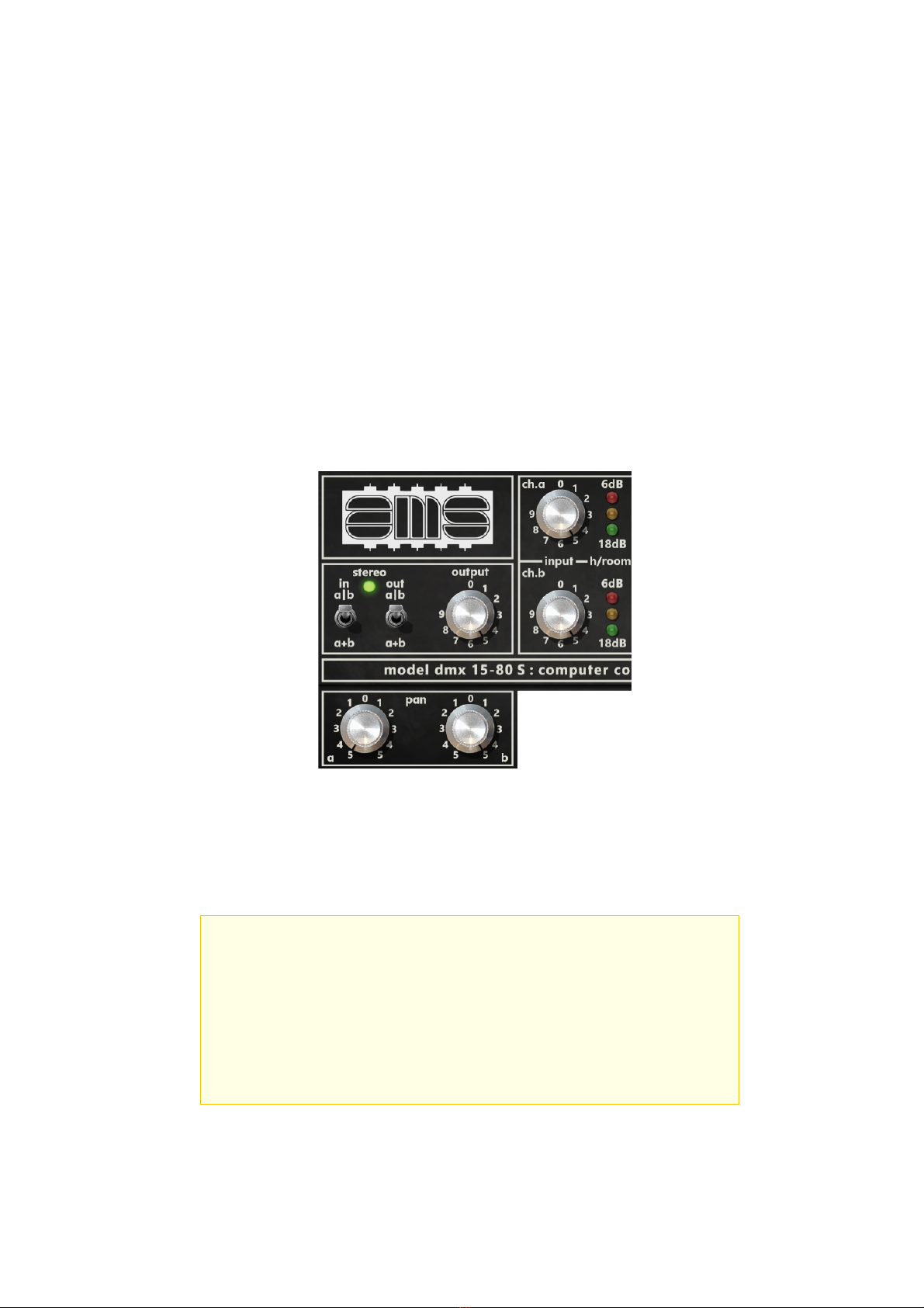
DMX 15-80 S : Digital Delay / Pitch Shifter
AMS DMX 15-80 S Product Overview
Create Soundscapes and Textures with a Rare Vintage Digital Delay
Introduced in 1978, the AMS DMX 15-80 S was the world's first microprocessor controlled,
15-bit digital delay and pitch shifter. Used on classic albums by Joy Division, Nirvana,
Brian Eno, and many more, the AMS DMX is famous for adding its iconic '80's-era space
and depth.
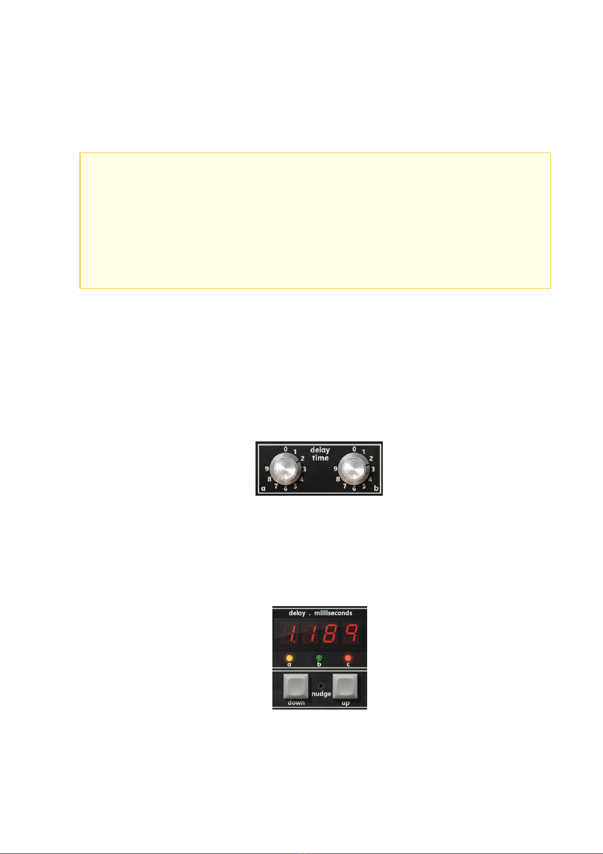
An Era-Defining Studio Processor
Upon its introduction, the AMS DMX was hailed as a digital wonder. Featuring two
independent delay channels, just over six seconds of delay time, and groundbreaking
“de-glitched” pitch shifting, its signature ambience gave artists characterful doubling,
delay, chorus, pitch shift, and ambient effects, from the '80s, to this day.
Add Sonic Intrigue to any Source
Use the AMS DMX Digital Delay & Pitch Shifter plug-in to add vintage digital dimension to
drum machines, synths, or guitars. You can also use it for automatic double tracking
effects and unique arpeggio patterns on vocals, horns, and more.
Plug-In Only Features
The AMS DMX plug-in not only gives you all the revision features of the vintage rackmount
units — including the rare expansion chorus controller module — you get modern upgrades
like Tempo Sync, Dual VCO mode, Dry/Wet Mix, Wet Solo, and more.
The Perfect Partner for AMS RMX16 Reverb
Combine the AMS DMX Digital Delay plug-in with the AMS RMX16 Digital Reverb plug-in
for the ultimate in vintage digital processing, and give your productions the pioneering
sound of two legendary creative tools.
DMX 15-80 S Plug-In Features
• Record and mix with the world's only authentic AMS DMX Digital Delay plug-in, developed
by original hardware designer Mark Crabtree
• Add iconic delay and pitch shifting effects to drum machines, vocals, synths, guitars,
and more
• Get double tracking effects made famous by Prince, Radiohead, and Phil Collins
• Mix with Artist Presets from Chris Coady (Yeah Yeah Yeahs, Beach House), Chuck Zwicky
(Prince, Reggie Watts), Ivan Barias (Justin Timberlake, Jill Scott), and more