manuals.online logo
Brands
  1. Home
  2. •
  3. Brands
  4. •
  5. AMSOIL
  6. •
  7. Laboratory Equipment
  8. •
  9. AMSOIL BMK-30 User guide

AMSOIL BMK-30 User guide

BMK-30
A. Getting started
1. Check all parts against the parts list and inspect for damage.
2. Make sure you have the tools needed for the job.
Recommended tool list
Adjustable wrench Torque Wrench Drill
5
⁄
8
⬙wrench (2) Side Cutter
7
⁄
16
⬙drill bit
13
⁄
16
⬙wrench
15
⁄
16
⬙wrench Utility knife
Center punch
7
⁄
8
⬙wrench (2) Adjustable filter wrench
Hammer Oil drain pan Vice
B. Attaching the filter mount
1. Survey the engine compartment for possible mounting locations. Solid
structures such as the firewall, fender well, radiator support or frame are
normal locations. (Do not mount on engine.) See diagrams A and G
2. This filter system must be mounted vertically to operate properly.
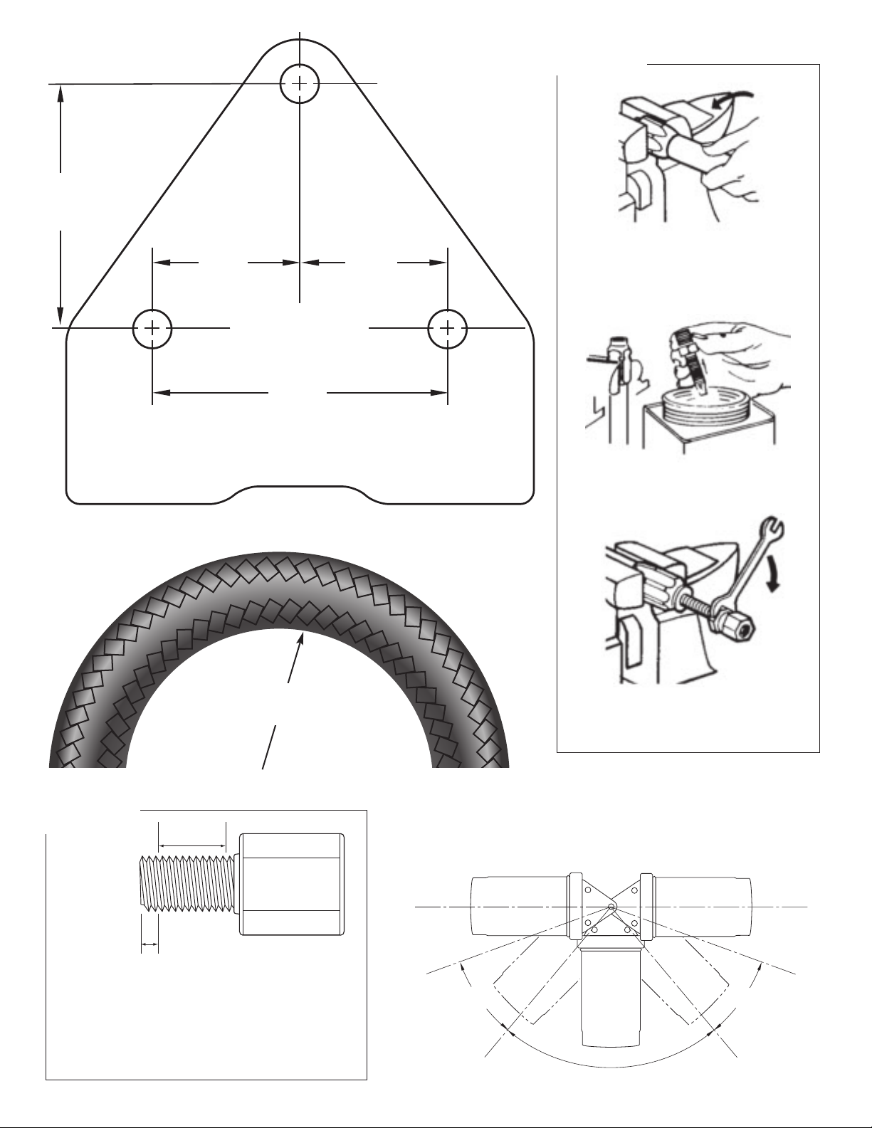
3. When the location has been determined, mark the area using the filter
mount as a template and mark the holes with a center punch and hammer.
See diagram B
4. Install adapter fittings (BP-190) on filter mount (BK-305) using PST or
thread tape. Using a
13
⁄
16
⬙wrench, tighten fittings 2-3 turns beyond
finger tight.
5. With a
7
⁄
16
⬙drill bit, drill out the previously marked mounting holes and
attach the filter mount using the
7
⁄
16
⬙bolts, nuts, small washers and fender
washers provided. The bolts should be tightened to 20 foot pounds.
5
⁄
8
⬙
wrenches or socket will be required for this operation.
6. Fill the By-Pass Filter element (EaBP-120) with the same motor oil being
used in the vehicle. Lubricate the filter gasket with oil and spin filter onto
mount. Tighten per instructions on the filter.
C. Oil Supply
1. Locate a pressurized oil port such as a gallery port, pressure sender port,
etc. Note: AMSOIL recommends adapting off of the pressurized oil port
using a fitting(s) to accept the
1
⁄
2
⬙JIC female hose end provided in this
kit. Purchase of adapters for your specific application is required.
2. Measure the amount of hose (BP-250, Purchased Separately) needed to
run from the pressurized oil port. Using a utility knife, squarely cut the hose
to the proper length.
3. Install hose fittings (BP-260) on both ends of the hose following the
instructions noted in diagram F. Tools required are one
7
⁄
8
⬙and one
15
⁄
16
⬙
wrench or vise.
Note: The hose and fittings supplied with this kit have been matched to
provide maximum performance and life expectancy. Interchanging with
other types or brands is not recommended and should be avoided.
Should additional hose be required, it may be obtained from AMSOIL by
ordering part number BP-250. Do not use any form of thread sealant any-
where on the BP-260 hose fittings.
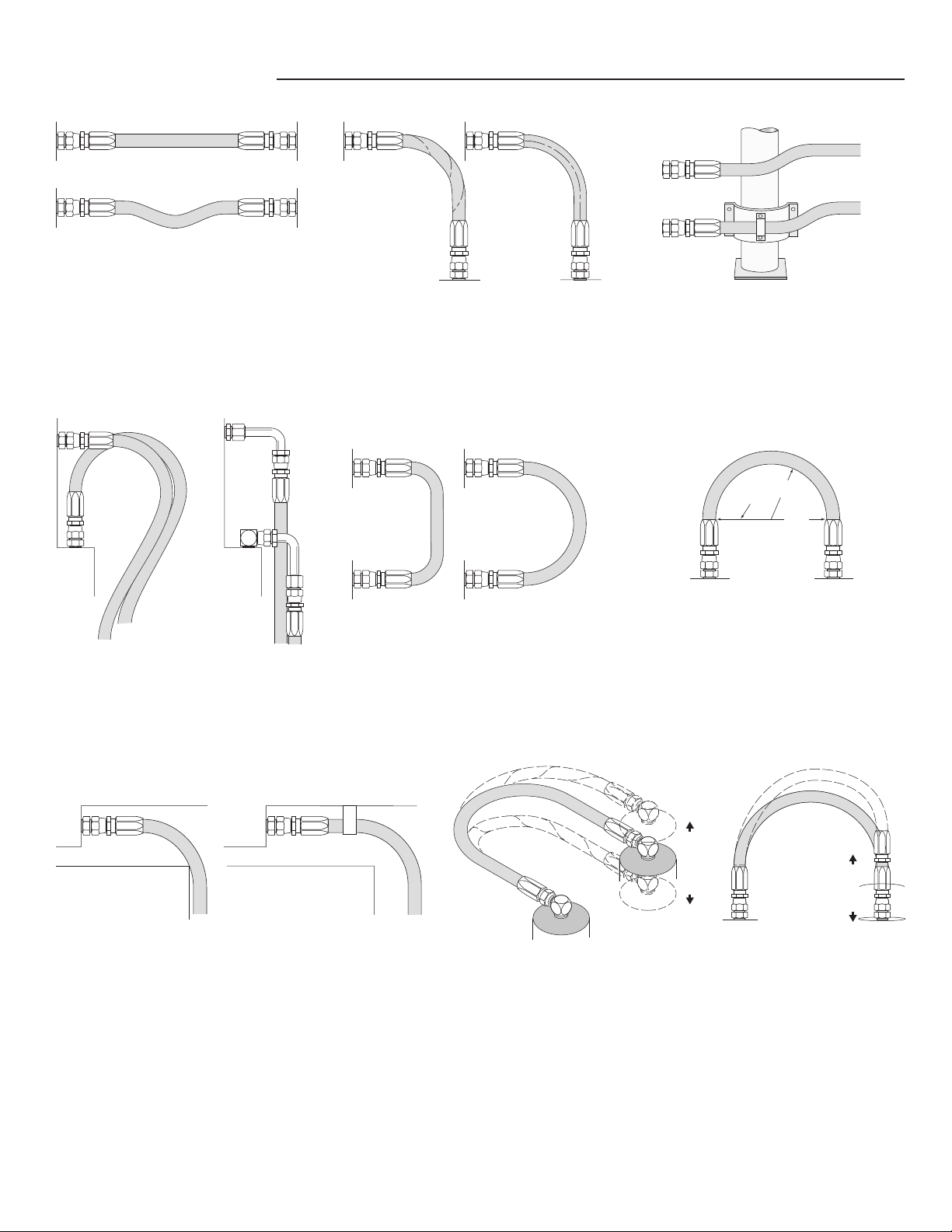
4. Route and connect the hose assembly to the filter mount (BK-305) at the
IN port see diagram C and to the
1
⁄
2
⬙JIC male fitting at the pressurized
oil port, making sure the hose does not contact any hot or moving sur-
faces or sharp edges. Ensure a minimum of a
3
⁄
4
⬙bend radius is main-
tained at all corners. Also, bends in hose should not begin at hose
fittings. See diagrams D and H
5. Using two
7
⁄
8
⬙wrenches, tighten hose fitting swivel nuts to 525-575
inch pounds or from finger tight, rotate an additional 60° or
1
⁄
6
of a turn.
Note: Do not use any form of thread sealant anywhere on the hose fittings.
D. Oil Return
1. The outlet of the by-pass unit (BK-305) should be connected to a low pres-
sure or free oil return to the crankcase or sump of the engine. Many heavy
duty diesels have access ports on the side of the oil pan or at the oil fill
tube.
2. Measure the amount of hose (BP-250, Purchased Separately) you will
need to run from the filter mount (BK-305) to the low pressure oil outlet
on the engine.
Note: AMSOIL recommends adapting off of the crankcase or sump port
using a fitting to accept the
1
⁄
2
⬙JIC female hose end provided in this kit.
Purchase of adapters for your specific application is required.
3. Using a utility knife, squarely cut the hose to the proper length.
4. Install hose fittings (BP-260) on both ends of the hose following the
instructions noted in diagram F. Tools required are one
7
⁄
8
⬙and one
15
⁄
16
⬙wrench or vise.
5. Route and connect the hose assembly to the filter mount (BK-305) at the
OUT port see diagram C and to the
1
⁄
2
⬙JIC male fitting at the low pres-
sure oil port, making sure the hose does not contact any hot or moving sur-
faces or sharp edges. Ensure a minimum of a
3
⁄
4
⬙bend radius is maintained
at all corners. Also, bends in hose should not begin at hose fittings.
6. Using two
7
⁄
8
⬙wrenches, tighten hose fitting swivel nuts to 525-575
inch pounds or from finger tight, rotate an additional 60° or
1
⁄
6
of a turn.
Note: Do not use any form of thread sealant anywhere on the hose fittings.
7. Use plastic ties (BP-46) to secure hose in position and away from
damage. Trim ties using side cutter.
Note: Over tightening the plastic ties can restrict oil flow.
5. Record vehicle mileage/operating hours and date of installation.
E. Start up procedures
1. Check that all fittings and hoses are securely attached, and that the
hoses are routed properly.
2. Check engine oil level. Fill to full mark if necessary.
3. Set vehicle parking brake. With transmission in park/neutral start the engine
and immediately check oil pressure. Note: Pressure may initially take a
moment or two to rise. Caution: Carefully check for leaks at fittings, hoses
and mount. If leaks are observed,
STOP ENGINE IMMEDIATELY,
repair
leaks and continue.
IMPORTANT NOTICE
Read all instructions completely before attempting to install this unit.
Improper installation could result in serious system and/or equipment
damage. The installation of this system is not difficult, however, some
mechanical ability is necessary. If you are not comfortable with the
instructions or have questions, do not attempt the installation. Consult
a mechanic or contact AMSOIL INC. for further instructions or assistance.
If installing on a Japanese- or European-built vehicle utilizing Metric or
B.S.P. threads, additional parts may be required. Consult step D.1
before you continue.
WWAARRNNIINNGG::This filter system is not designed to replace the engine’s
normal full-flow filter. Do not attempt to install a by-pass filter element
in place of the existing full-flow filter.
WWAARRNNIINNGG::Extreme care should be taken to avoid bodily harm during
installation. Before starting, ensure the engine is cool to avoid burns and
never work in the engine compartment area with the engine running.
Heavy-Duty By-Pass Filtration System
Installation and Servicing Instructions
BMK30_90358 6/6/08 7:50 AM Page 1
EaBP-120
171⁄2 ⬙
6⬙
45⁄8⬙
OUT
IN OUT
IN
Diagram A
MINIMUM AREA NEEDED FOR
DUAL MOUNT AND SPIN-ON
OIL FILTER ELEMENTS
* Mount and element heights
plus 1-inch removal clearance
OUT
IN OUT
IN
Oil Pressure Line
AMSOIL By-Pass Filter
EaBP-120
Oil Return Line
2
2
10
10
2
2
3
3
4
6
5
7
1
Engine
Oil Pan
Pressurized
Oil Port
4
4. After engine has warmed, shut off and re-check engine oil level. Fill as nec-
essary.
5. Record vehicle mileage/operating hours and date of installation.
F. Periodic maintenance
1. Periodic visual inspection of the fittings and hoses is recommended. Check
for leaks, hose deterioration and cuts. Repair and/or replace as necessary.
2. Refer to Recommended Filter Change Interval chart for servicing intervals.
3. To change the filter element:
a. Ensure engine is off and use caution as the engine, oil and filter may
be hot and could result in an injury.
b. Using a filter wrench, remove the filter element. Dispose of properly.
Diagram C
Parts and Assembly List
Item Description AMSOIL Part Number Quantity
1. Filter Mount BK305 1
2.
13
⁄
32
⬙Hose Fitting BP260 4
3.
3
⁄
8
⬙NPT X
1
⁄
2
⬙JIC BP190 2
4. Instruction Sheet BP30 1
5.
7
⁄
16
⬙Flat Washer BP285 3
6.
7
⁄
16
⬙Fender Washer BP286 3
7.
7
⁄
16
⬙-14 x 1
1
⁄
2
⬙Bolt BP287 3
8.
7
⁄
16
⬙-14 Ny lock Nut BP288 3
9. 6” Nylon Cable Tie BP46 6
10.
13
⁄
32
⬙ID Hose BP250 Purchased Separately
c. Clean the filter gasket contact area on the mount with a clean, lint-free rag.
d. Lubricate the new filter gasket with clean oil.
e. Fill filter as full as possible with engine oil.
f. Screw on new filter, tighten per instructions on the filter.
g. Start engine and check for leaks.
h. Check engine oil level, fill as needed.
i. Record vehicle mileage/operating hours for future reference.
Diesel Powered Engines: Due to higher oil contamination levels in diesel
engines and variance in fuel quality, maintenance intervals for the filter ele-
ment and oil change intervals should be determined using oil analysis. For
more on oil analysis see the last page.
Oil Pressure Line
Oil Return Line
BMK30_90358 6/6/08 7:50 AM Page 2
Diagram E
SEALANT
AREA
NO SEALANT
ON FIRST 1-2 THREADS
Note: If Teflon tape is used, it should be wrapped no
more than 1
1
⁄
2
to 2 turns in a clockwise direction
when viewed from the thread end.
Caution: More than two turns of tape may cause distor-
tion or cracking of the port. Never back off
(loosen) pipe threaded connectors to achieve
alignment.
ACCEPTABLE
ANGLE
ACCEPTABLE
ANGLE
PREFERRED MOUNTING ANGLE
HORIZONTAL
0°
20°
50°
130°
160°
180°
Mounting Angle Diagram G
(Recommendations are the same right to left and front to back)
Mounting angle above horizontal is not recommended
27⁄8⬙
23⁄8⬙
17⁄16⬙17⁄16⬙
Diagram F
2. Oil inside of hose and nipple threads liberally
with oil. Do not oil hose cover.
3. Screw nipple assembly into socket using
wrench on nipple hex until nipple hex
shoulders against socket.
Diagram D
Minimum Bend
Radius
(Actual size)
1
1
⁄
2
⬙(1.5)
13
⁄
32
⬙I.D. Hose BP-188
Diagram B
1. Place socket in vice and screw in hose
counter-clockwise until hose bottoms. Back
hose out
1
⁄
2
turn.
BMK30_90358 6/6/08 7:50 AM Page 3
AMSOIL By-Pass Warranty
AMSOIL INC. warrants each AMSOIL By-pass System to be free from defects in material
and workmanship for a period of one year from the time of purchase. THIS WARRANTY
DOES NOT APPLY IF THE BY-PASS SYSTEM HAS BEEN IMPROPERLY
INSTALLED, ABUSED, DAMAGED, USED IN COMPETITIVE RACING OR ON
MODIFIED ENGINES OR IF USED IN ANY AIRCRAFT OF AVIATION APPLICA-
TION. AMSOIL INC. DOES NOT MAKE BY-PASS RECOMMENDATIONS FOR
AIRCRAFT OR AVIATION USE. If your AMSOIL By-pass System is found to be defec-
tive within a period of one year from the time of purchase, AMSOIL INC. will replace the By-
pass System or defective component with another AMSOIL By-pass System or component or
refund or credit the AMSOIL Dealer’s or customer’s account. AMSOIL will reimburse you
for the reasonable costs of the parts and labor required to repair your engine or equipment to
the extent the damage was solely attributable to a defect in your AMSOIL By-pass System.
In order to obtain engine or equipment repairs under this warranty the Dealer or customer must
directly contact AMSOIL Technical Service, AMSOIL INC., 1101 Susquehanna Ave.,
Superior WI 54880, Tel: 715-399-TECH (8324). The customer must also allow the AMSOIL
Technical Services Department to examine the By-pass System or Filter(s) and, if required,
the engine or equipment, to determine the extent of damage and whether it was caused by a
defective AMSOIL By-pass System or Filter(s). The By-pass System and Filter(s) must be
returned, in its original, undamaged condition, to the AMSOIL Technical Service Department
for examination. This warranty is exclusive of any other warranty, express or implied.
AMSOIL BY-PASS SYSTEMS EXPRESSLY DISCLAIMS, WITHOUT LIMITATION,
THE IMPLIED WARRANTIES OF MERCHANTIBILITY AND OF FITNESS FOR A
PARTICULAR PURPOSE. The foregoing states the entire AMSOIL By-pass System’s
exclusively liability and the buyer’s exclusive and sole remedy for any damages or claim made
in connection with the sale of an AMSOIL By-pass System. AMSOIL By-pass Systems
shall in no event be liable for any special, incidental, or consequential damages whatsoever,
except those specifically provided for in this warranty. Some states do not allow the exclusion
or limitation of incidental or consequential damages, so the above limitations or exclusion may
not apply to you. This warranty gives you specific legal rights and you may also have other
rights, which vary from state to state.
BMK30_90358 6/6/08 7:50 AM Page 6
BP-46
BP-260
Order Separately
BP-250
PLASTIC TIE
HOSE FITTING
13
⁄
32
⬙HOSE
(6)
(4)
AMSOIL BP - 250
BMK-30 PARTS IDENTIFICATION SHEET
BP-285
BP-288
BP-287
BP-286
7
⁄
16
⬙I.D. WASHER
7
⁄
16
⬙NUT
7
⁄
16
⬙-14 X 1
1
⁄
2
⬙
BOLT
7
⁄
16
⬙FENDER
WASHER
(3)
(3)
(3)
(3)
BK-305
FILTER MOUNT
NOT TO SCALE
(1)
BP-190
“O” RING
FITTING
ADAPTER
(2)
BMK30_90358 6/6/08 7:50 AM Page 5
11..PPrroovviiddeeffoorrlleennggtthhcchhaannggee
In straight hose installations allow enough slack in
the hose line to provide for changes in length that will
occur when pressure is applied. This change in length
can be from +2% to -4%.
RIGHT
WRONG
44..AAvvooiiddmmeecchhaanniiccaallssttrraaiinnss
Use elbows and adapters in the installation to relieve
strain on the assembly, and to provide easier and
neater installations that are accessible for inspection and
maintenance.
WRONG
RIGHT
77..SSeeccuurreeffoorrpprrootteeccttiioonn
Install hose runs to avoid rubbing or abrasion. Use clamps to support long runs
of hose or to keep hose away from moving parts. It is important that the clamps
do not allow the hose to move. This movement will cause abrasion and pre-
mature hose failure.
RIGHT
WRONG
88..AAvvooiiddIImmpprrooppeerrHHoosseeMMoovveemmeenntt
Make sure relative motion of the machine components produces bending rather than twist-
ing of the hose. Hose should be routed so that the flex is in the same plane as the equipment
movement.
RIGHT
WRONG
55..UUsseepprrooppeerrbbeennddrraaddiiuuss
Keep the bend radius of the hose as large as possible
to avoid collapsing of the hose and restriction of flow.
Follow catalog specs on minimum bend radii.
RIGHT
WRONG
66..UUsseepprrooppeerrbbeennddrraaddiiuuss((ccoonntt..))
Maximum bend radius is measured on the inside bend
of the hose. To determine minimum bend, divide the
total distance between ends (B length) by 2. For exam-
ple B = 6, minimum bend radius = 3.
3.00⬙
RADIUS
6.00⬙
DIAMETER
B
22..AAvvooiiddttwwiissttiinnggaannddoorriieennttpprrooppeerrllyy
Do not twist hose during installation. This can be deter-
mined by the printed layline on the hose. Pressure
applied to a twisted hose can cause hose failure or
loosening of connections.
RIGHT
WRONG
33..PPrrootteeccttffrroommhhaazzaarrddoouusseennvviirroonnmmeenntt
Keep hose away from hot parts. High ambient temper-
atures will shorten hose life. If you can not route it
away from the heat source, insulate it.
WRONG
RIGHT
Diagram H
AMSOIL INC., AMSOIL Bldg., Superior, WI (715) 392-7101 BP-174
Hose routing examples
BMK30_90358 6/6/08 7:50 AM Page 4

Popular Laboratory Equipment manuals by other brands

Steinberg Systems SBS-LZ-300 user manual

Steinberg Systems

Steinberg Systems SBS-LZ-300 user manual

Neuation iFUGE M08VT Product user manual

Neuation

Neuation iFUGE M08VT Product user manual

Thermo Scientific Revco Installation and operation

Thermo Scientific

Thermo Scientific Revco Installation and operation

INTEGRA Biosciences VIAFLO 96 quick start guide

INTEGRA Biosciences

INTEGRA Biosciences VIAFLO 96 quick start guide

CBM SST 1700B instruction manual

CBM

CBM SST 1700B instruction manual

multivac P300 instruction manual

multivac

multivac P300 instruction manual

Glass Expansion 70-803-1923 instruction manual

Glass Expansion

Glass Expansion 70-803-1923 instruction manual

tecan Columbus Washer Technical manual

tecan

tecan Columbus Washer Technical manual

Teledyne CombiFlash Companion XL installation guide

Teledyne

Teledyne CombiFlash Companion XL installation guide

OHAUS Frontier FC5513 instruction manual

OHAUS

OHAUS Frontier FC5513 instruction manual

Zeiss MCU 2008 operating manual

Zeiss

Zeiss MCU 2008 operating manual

VERDER Carbolite Gero HT 5/95 Installation, operation and maintenance instructions

VERDER

VERDER Carbolite Gero HT 5/95 Installation, operation and maintenance instructions

Idex Trebor PC6 Operation & maintenance manual

Idex

Idex Trebor PC6 Operation & maintenance manual

SciCan STATIM troubleshooting guide

SciCan

SciCan STATIM troubleshooting guide

Millipore Millicell MDCI10000 user guide

Millipore

Millipore Millicell MDCI10000 user guide

manvia DG-50 Installation, operation & maintenance manual

manvia

manvia DG-50 Installation, operation & maintenance manual

Hanil T04 quick guide

Hanil

Hanil T04 quick guide

BIO RAD Helios Gene Gun System instruction manual

BIO RAD

BIO RAD Helios Gene Gun System instruction manual

manuals.online logo
manuals.online logoBrands
  • About & Mission
  • Contact us
  • Privacy Policy
  • Terms and Conditions

Copyright 2025 Manuals.Online. All Rights Reserved.