manuals.online logo
Brands
  1. Home
  2. •
  3. Brands
  4. •
  5. Queensgate
  6. •
  7. Laboratory Equipment
  8. •
  9. Queensgate NANOSCAN OP400 Programming manual

Queensgate NANOSCAN OP400 Programming manual

PLEASE READ THE INSTRUCTIONS BEFORE
ATTEMPTING TO USE THE NANOSCAN OP400 SYSTEM
IDENTIFYING YOUR SYSTEM COMPONENTS
INSTALLING YOUR SYSTEM
•Save this manual as it contains important safety information and operating instructions.
•Before using the system, please follow and adhere to all warnings, safety and operating instructions located on the product
and in this user manual.
•Do not expose the product to open flames, extreme hot or cold temperatures, water or moisture.
•Do not allow objects to fall on or liquids to spill on the product.
•Connect the AC power cord only to designated power sources as marked on the product.
•Make sure the electrical cord is located so that it will not be subject to damage.
•To reduce the risk of damage, unplug the product from the power source before connecting the components together.
•DANGER - never alter the AC cord or plug. If the plug will not fit into the outlet, have a proper outlet installed by a qualified
electrician.
•Use only the proper type of power supply cord set (provided with the system) for this unit.
•Do not attempt to disassemble the product. Doing so will void the warranty. This product does not contain
consumer serviceable components. Service should be performed by authorized service centers.
NANOSCAN OP400 QUICK START INSTRUCTIONS
The standard NanoScan OP400 system consists of:
(1)- NanoScan OP400 Piezo Objective Scanner
(1)- NPC-D-6110 Controller and power supply
(1) - Microscope Thread Adapte
(1) - 1.3mm (0.05 inch) Hex Key + (1) tightening key
(1) - Objective Lens Thread Adapter (optional)
(1) - Objective Lens Spacers (optional)
(1) - 9 pin gender changer for RS232C QG-0494-SK-200001
(1) - USB Cable QGPA0096-SK-102 + (1) 1.2 metre BNC to BNC
cable QGBNCCAB + (1) RS232C QG-0494-SK-200002
(1) - USB stick containing manuals and test reports
NanoScan OP400 Piezo
Objective Scanner
Gender
changer for
RS232C
www.prior.com
STEP 1: Select the position for the
OP400 on the nosepiece.
STEP 2: Insert the microscope thread adapter
using the key provided. Insert parfocal spacer
if other objectives are to be used.
STEP 3: Connect the OP400 to the
nosepiece. Tighten both grub screws
with the hex key.
STEP 4: Insert the objective lens using the
appropriate objective lens adapter. Note no
adapter is necessary for M32. Other
objectives can be inserted into the nose piece
using option parfocal spacers.
STEP 5: The OP400 unit
is now properly installed.
Please take care with the cabling. Under no circumstances use the cabling to hold the stage.
Parfocal
Objective Spacer
Tightening Key Objective Lens
Thread Adapter
Microscope
Thread Adapter
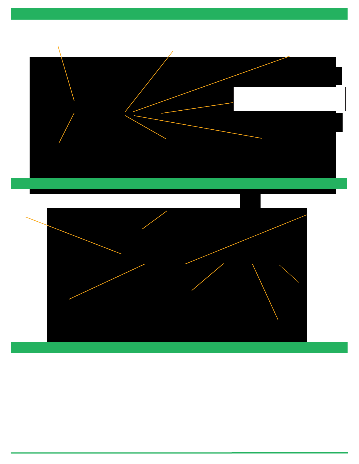
CONNECTING YOUR SYSTEM - FRONT OF UNIT
www.prior.com
POS MON connector Analogue
position monitor output BNC
connector(s)
Single ended output(s).
ANA I/P” connector
Signal used to control the stage position
Analogue command input
BNC connector(s)
Single ended output(s).
On/Off switch
Earth Stud - M4 threaded stud
Provides additional ground connection to reduce interference of
background electrical noise. Do not raise above 0V ground potential
PWR Connector
Provides power to controller electronics.
4 pin mini-DIN with screen Input
+24V dc ±0.75V @ 5A
ONLY connect an approved power supply.
Digital I/O connector
Provides digital inputs and outputs for interfacing controller
to external equipment.
TRIG inputsand outputs
IN_POS Output
Stepped input and outputs
25 pin D-type socket; 5V TTL input/output
MUST use shielded cable.
Ethernet Connector
for upgrading firmware
USB type B connector
Used to communicate with a
computer running
Nanobench or using using
DLL commands
SYNC IN/OUT connector
Provides RS232C connection with
connected computer using supplied
gender changer adapter.
Power Indicator LED
Indicates the power status and controller ready
RED steady = Controller configuring/not ready (can
take up to 30 seconds).
GREEN steady = Controller powered and ready for
operation
CLOSED INDICATOR LED
Indicates the status of control Loop
OFF = Stage NOT connected
ORANGE = Stage settings being loaded on connection
RED = Controller operating in OPEN loop mode
GREEN = Controller operating in CLOSED loop mode
YELLOW = Controller servo output frozen
COMS Indicator LED
Indicates status of communications with connected
computer.
Not lit = No communications taking place.
GREEN lit or flashing = Communications active
IN POS Indicator LED
Indicates the status of the stage position in CLOSED
loop mode.
OFF = Stage has not reached desired position.
ORANGE = Stage settings being loaded on connection
GREEN = Stage has reached the desired position
Nano Mechanism Connector – connect the OP400
to this position.
NOTE High Voltage present on connector – up to
160VDC
CONNECTING YOUR SYSTEM - BACK OF UNIT
TURNING ON YOUR SYSTEM
1. Once the stage is mounted, connect it to the controller ensuring that the connector screws are tightened to the controller lock
posts. On powerup, the controller will always move the stage across its range to carry out auto-calibration. It is important
to ensure that there is sufficient clearance between the lens, sample and illumination to allow this to take place. If the
temperature or load change significantly the stage can 'clip at one end of the travel. Should this happen restart your system to
allow autocalibration; this rebalances the stage so that the closed loop range is centred within the open loop range.
2. Connect Power to controller and the analogue input and/or USB as required.
3. Switch ON controller using switch on rear panel. After approx. 30 seconds, the relevant stage channel should show two green
lights (CLOSED and IN-POS). This indicates the stage is operating in the CLOSED loop mode and IN-POS LED indicates stage
has reached position within a pre-defined band.
4. The analogue input and POS MON output is 0V to +10V giving a scale factor of 40µm/volt. The analogue input is enabled by
default.
5. The system has 8 memory positions for PID settling (accessible via the USB interface). The default setting is for objective loads
from 150g to 500g. An optimised setting providing a faster settle time for loads up to 350g can by selected using Nanobench. The
next section demonstrates how to change to other settings.
SOFTWARE
The standard customer-facing application for the system is called ‘Nanobench 6000’, and is included on the USB drive included
in the shipment. This also includes software or links to software which must be installed before the software can be used.
Start Nanobench - the screen displayed will be similar to the one show below:
www.prior.com
Select the correct COM port within Nanobench 6000, then click ‘Connect’: At this point the software should connect to the
controller and begin reading the live measured position.
Visual C++ Runtime
Labview Runtime Engine 2017 SPI F3
‘Nanobench 6000’ runs on Windows XP, 7, 8, 10.
Once Nanobench and associated software has been installed and controller functional, go to Windows Device Manager,
and find the COM port that the controller is connected to (e.g. ‘COM12’)
SOFTWARE
www.prior.com
Dynamic Setups
The OP series stages come pre-loaded with ‘dynamic setups’, which allow the stage/controller to operate with a range of
different objective loads, optimize step settle times and resolutions.
To swap between these setups the controller must be unlocked to at least ‘User’ security. The setups can then be changed by
selecting a new setup in the ‘Preset’ dropdown, then clicking ‘Load Preset’:
To change the security level, simply open the ‘Lock Status’ drop down and select the appropriate lock state. A warning is
displayed to ensure the user knows that unlocking the controller exposes commands that can potentially cause damage to the
stage if set incorrectly. In most cases, a security level of ‘User’ is best, as it allows access to most commonly needed settings
while still keeping more important settings ‘locked’.
Presets
The QGOP-400-UP/QGOP-400-INV/QGOP-400UP-HL and QGOP-400-INV-HL come with stored settings which have been
optimized for fast step settle times and objective loads. The presets can be changed by selecting a new preset in the 'Preset'
dropdown, then clicking 'Load'. The test report provided with your OP400 provides information on the presets for your device.
Please note that the presets will revert to the default preset on power-down of the controller.
Caring For Your Stage
• When the stage is not in use for long periods it is advisable to either power down the stage or leave the command at midpoint.
This will help to ensure a long life.
•Avoid using the stage above 60% relative humidity for long periods.
• For loads greater than 600g please specify as the stage must be setup to support this. Default settings are optimized for
150 -500g objective lens plus sample holder with a very fast setting for objective loads to 350g objective. Higher loads can be
optimized on request.
•The cable is sensitive - do not lift the stage by the cable or bend beyond the 30mm radius.
External Control
The QGOP-400-UP/QGOP-400-INV/QGOP-400UP-HL and QGOP-400-INV-HL can be controlled from Prior ProScan,
Micromanager, Metamorph and Ni Elements. Quickstart quides are available.
DLL commands are available for interfacing with other software and integration into OEM systems.

Popular Laboratory Equipment manuals by other brands

Idexx Quanti-Tray Sealer PLUS user manual

Idexx

Idexx Quanti-Tray Sealer PLUS user manual

Koehler K18854 Operation and instruction manual

Koehler

Koehler K18854 Operation and instruction manual

logos biosystems LUNA-II user manual

logos biosystems

logos biosystems LUNA-II user manual

Bullard Edge Thermal Imager user manual

Bullard

Bullard Edge Thermal Imager user manual

BEVS 2501/3A user manual

BEVS

BEVS 2501/3A user manual

Klein Tools TI290 instruction manual

Klein Tools

Klein Tools TI290 instruction manual

Biobase BOV-V30F Maintenance manual

Biobase

Biobase BOV-V30F Maintenance manual

Gemlogis LEO User handbook

Gemlogis

Gemlogis LEO User handbook

Fluke ii900 user manual

Fluke

Fluke ii900 user manual

EXFO IQS-636 user guide

EXFO

EXFO IQS-636 user guide

Hydac OFX Operating and maintenance instructions

Hydac

Hydac OFX Operating and maintenance instructions

Stereotaxis Niobe PM3.1 Installation Verification and Testing

Stereotaxis

Stereotaxis Niobe PM3.1 Installation Verification and Testing

MKS Cirrus2 Hardware manual

MKS

MKS Cirrus2 Hardware manual

Magellan LeadCare II Quick reference guide

Magellan

Magellan LeadCare II Quick reference guide

Thermo Scientific 88870001 operating manual

Thermo Scientific

Thermo Scientific 88870001 operating manual

Azure Biosystems Cielo AIQ030 user manual

Azure Biosystems

Azure Biosystems Cielo AIQ030 user manual

Qiagen PyroMark Q24 MDx user manual

Qiagen

Qiagen PyroMark Q24 MDx user manual

Hanna Instruments HI 190 instruction manual

Hanna Instruments

Hanna Instruments HI 190 instruction manual

manuals.online logo
manuals.online logoBrands
  • About & Mission
  • Contact us
  • Privacy Policy
  • Terms and Conditions

Copyright 2025 Manuals.Online. All Rights Reserved.