- 3 -
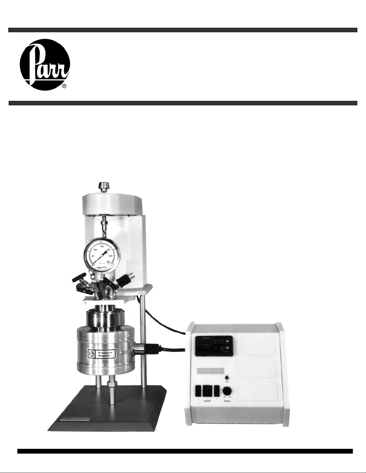
4560 Mini Bench Top Reactors
Parr Instrument Company
Revision 6-28-02
Scope
These instructions describe the
installation, operation and maintenance of
Parr Series 4560 Mini Bench Top Reactors
offered in sizes from 100 mL to 600 mL.
They cover the basic steps to be followed for
installing these reactors and describe the
function of all standard components. They
are intended to be used in conjunction with
several related instruction sheets listed on
the previous page. This information
describes several components that are
common to most Parr pressure reaction
equipment, and includes safety precautions
and other related information applicable to
all reaction laboratories. The users should
study all of these instructions carefully
before starting to use these vessels so that
they will fully understand the capabilities and
limitations of the equipment.
Users Responsibility
All Parr Reactors and pressure
vessels are designed and manufactured with
great care to assure safe operation when
used within their prescribed temperature and
pressure limits.
But . . . the basic responsibility for safety
when using this equipment rests entirely
with the user; who must:
1. Select a reactor or pressure vessel
that has the capability, pressure rating,
corrosion resistance and design features
that are suitable for its intended use.
Parr engineers will be glad to discuss
available equipment and material options
with prospective users, but the final
responsibility for selecting a reactor or
pressure vessel that will perform to the
user’s satisfaction in any particular
reaction or test must rest with the user –
not with Parr.
In exercising the responsibility for the
selection of pressure equipment, the
prospective user is often faced with a
choice between over or under-designed
equipment. The hazards introduced by
under-designed pressure vessels are
readily apparent, but the penalties that
must be paid for over-designed
apparatus are often overlooked.
Recognizing these criteria, Parr reactors
and pressure vessels are offered in
several different styles, each designed
for convenient use in daily operation
within certain temperature and pressure
limits, using gaskets, closures and other
elements carefully selected for safe
operation within the limits specified for
that design. But in order to preserve the
validity of these designs, all temperature
and pressure limits must be observed,
and no attempt should be made to
increase these limits by making
alterations or by substituting components
which are not recommended by Parr
Instrument Company.
2. Install and operate the equipment within
a suitable barricade, if required, with
appropriate safety accessories and in full
compliance with local safety codes and
rules.
3. Establish training procedures to
ensure that any person handling the
equipment knows how to use it properly.
4. Maintain the equipment in good
condition and establish procedures for
periodic testing to be sure the vessel
remains structurally sound.
Unpack Carefully
Unpack the equipment carefully and
check all the parts against the, packing list.
If shipping damage is discovered, report it
immediately to the delivering carriers. The
vessel, motor, heater, and temperature
controller may be packed separately for
convenience in shipping, but these parts are
easily reassembled. Examine the
components closely for any loose parts or
shipping damage and be sure to check all
layers of packing materials thoroughly so as
not to overlook any parts which might
otherwise be discarded.