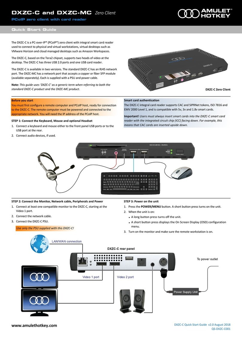
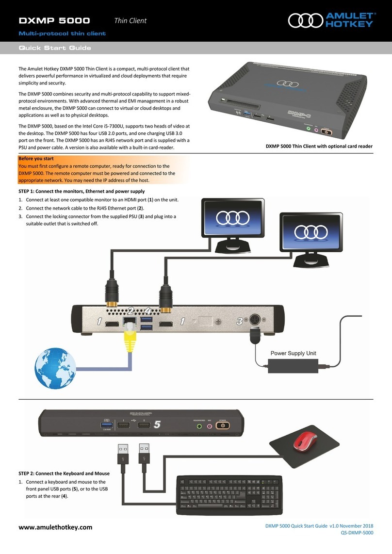
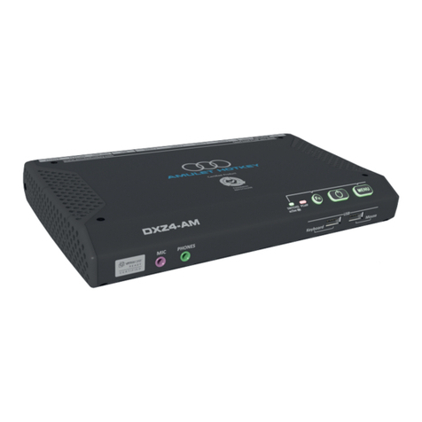
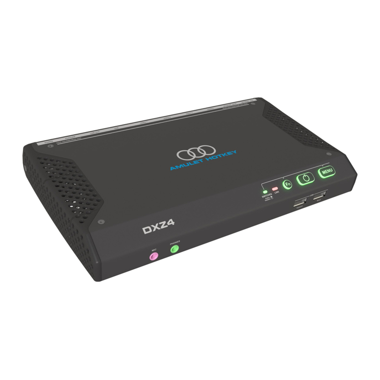
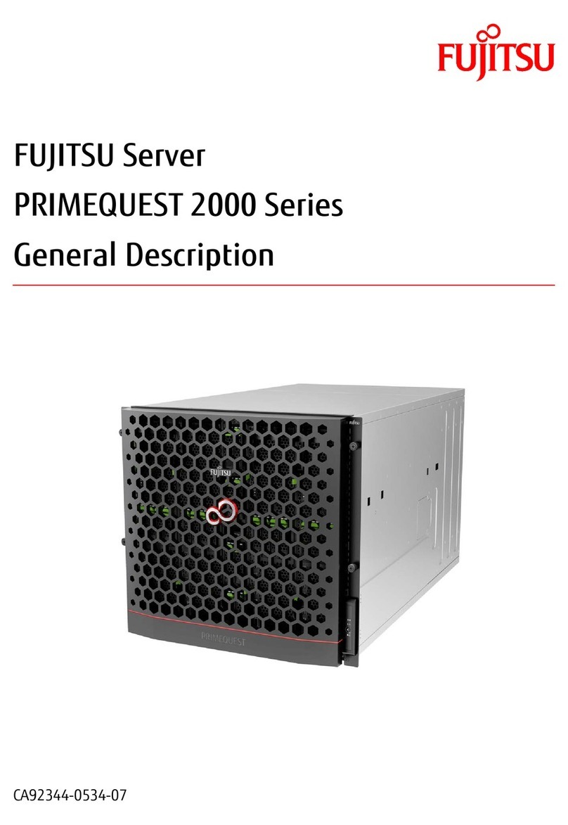
Amulet Hotkey CoreStation Series User manual

®
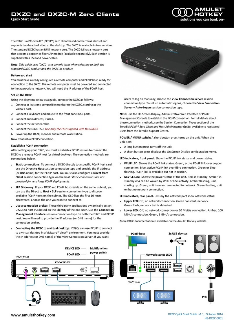
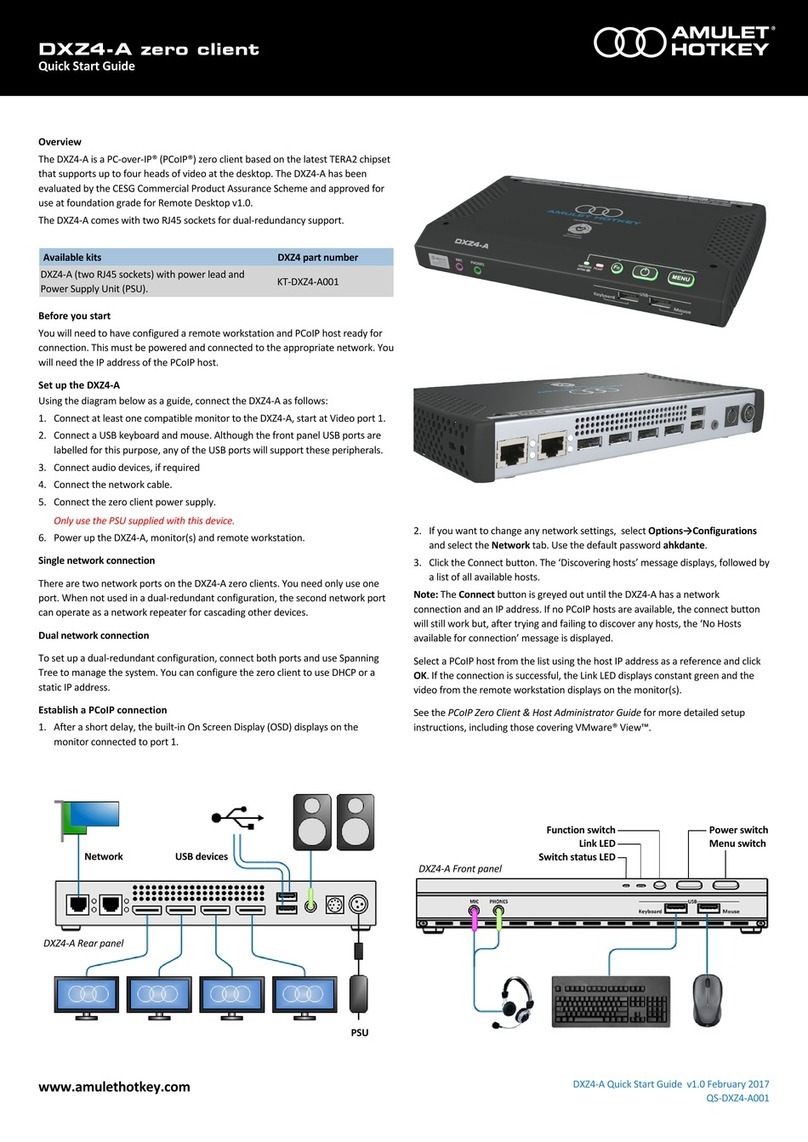
Remote desktop configuRation
User manUal
CoreStaon and DXM Series Blades
HB-CONF-0001
Revision 1.4 May 2020

Thank you
Thank you from everyone at Amulet Hotkey for purchasing this
product. Much me and energy has gone into making this the
best and most reliable soluon available. We are condent we
have provided a state-of-the-art unit that will provide you with
long and reliable service regardless of the applicaon.
To get the best from this product, follow this manual carefully.
Shipment and product inspecon
Your product was carefully packed prior to despatch to
guarantee safe transit. Make sure you thoroughly examine all
packaging and contents for signs of physical damage before use.
If any damage has occurred, nofy the shipping company and
your supplier immediately. Otherwise, claims for damage or
replacement may not be granted.
Retain the original packaging for use in the event that the
equipment has to be stored, shipped or returned for service.
If you choose to dispose of the packaging, please do so in an
environmentally friendly fashion.
Technical support
If you have further quesons , do not hesitate to contact
Amulet Hotkey technical support for expert assistance:
EMEA
+44 (0)20 7960 2400
eurosupport@amulethotkey.com
N America
+1 (212) 269 9600
ussupport@amulethotkey.com
South America
latamsupport@amulethotkey.com
Asia Pacic
+61 409 930 884
apsupport@amulethotkey.com
Or look at the resources page on our website:
hps://resources.amulethotkey.com/resources.
CAUTION
To prevent damage to the DXM Series Blades:
• install in accordance with these instrucons;
• always turn o and unplug the host computer
before handling the unit;
• always use appropriate an-stac handling
procedures when handling the unit;
• only use aachments and accessories
approved by Amulet Hotkey;
• do not expose the unit to moisture;
• do not place objects lled with liquids on or
near the unit;
• clean the unit only with a dry cloth;
• refer all servicing to qualied personnel.
©2020 Amulet Hotkey Ltd. All rights reserved.
The informaon contained in this document represents the current view of Amulet Hotkey® as of the date of publicaon. Because Amulet Hotkey must respond to
changing market condions, it should not be interpreted to be a commitment on the part of Amulet Hotkey, and Amulet Hotkey cannot guarantee the accuracy of any
informaon presented aer the date of publicaon. Secons of this document are reproduced with the kind permission of Teradici®Corp. This document is for informa-
onal purposes only. Amulet Hotkey make no warranes, express, implied or statutory, as to the informaon in this document. Complying with all applicable copyright
laws is the responsibility of the user. Without liming the rights under copyright, no part of this document may be reproduced, stored in or introduced into a retrieval
system, or transmied in any form or by any means (electronic, mechanical, photocopying, recording, or otherwise), or for any purpose, without express wrien per-
mission from Amulet Hotkey. Amulet Hotkey may have patents, patent applicaons, trademarks, copyrights, or other intellectual property rights covering subject maer
in this document. Except as expressly provided in any wrien license agreement from Amulet Hotkey, the furnishing of this document does not give you any license to
these patents, trademarks, copyrights, or other intellectual property. Teradici, PC-over-IP, and PCoIP are registered trademarks of Teradici Corporaon. VMware and View
are registered trademarks of VMware Corp. Amulet Hotkey and ‘soluons you can bank on’ are trademarks of Amulet Hotkey Ltd. The names of actual companies and
products menoned herein may be the trademarks of their respecve owners.
Product Information
Page 2
LASER SAFETY
The CoreStaon and DXM Series Blades may be
ed with SFP network modules that contain
Class 1 lasers. The SFP module emits invisible
radiaon which can cause harm if installed or
serviced incorrectly. Follow the guidelines below:
Warning: Class 1 laser product.
Warning: Invisible laser radiaon can be
emied from the aperture of the SFP port
when no bre is connected. To avoid exposure
to laser radiaon, do not stare into open
apertures.
Warning: Only trained and qualied personnel
may install, replace, or service this equipment.
FCC Noce
This device complies with part 15 of the FCC Rules. Operaon is subject to the following
two condions: (1) This device may not cause harmful interference, and (2) this device must
accept any interference received, including interference that may cause undesired operaon.
Title 47, Part 15 (47 CFR 15) of the Federal Communicaons Commission (FCC) Rules and
Regulaons establishes Radio Frequency (RF) emission limits for unlicensed emissions to
provide an interference-free radio frequency spectrum. Many electronic devices, including
computers, generate RF energy incidental to their intended funcon and are, therefore,
covered by these rules. These rules place computers and related peripheral devices into
two classes, A and B, depending upon their intended installaon. Class A devices are those
that may reasonably be expected to be installed in a business or commercial environment.
Class B devices are those that may reasonably be expected to be installed in a residenal
environment (personal computers, for example). The FCC requires devices in both classes to
bear a label indicang the interference potenal of the device as well as addional operang
instrucons for the user. A label on the device shows which class (A or B) the equipment falls
into. Class B devices have an FCC logo or FCC ID on the label. Class A devices do not have an
FCC logo or FCC ID on the label.
The DXM Series Blades has been tested and found to comply with the limits for a Class A
digital device, as dened by Part 15 of the FCC Rules. These limits are designed to provide
reasonable protecon against harmful interference when the equipment is operated in a
commercial environment. This equipment generates, uses, and can radiate radio frequency
energy and, if not installed and used in accordance with the instrucons, may cause harmful
interference to radio communicaons. Operaon of this equipment in a residenal area is
likely to cause harmful interference, in which case the user will be required to correct the
interference at their own expense.
EU Noce
• This product complies with EMC Direcve 2014/30/EU and the Low Voltage Direcve
2014/35/EU. Conformity is shown by compliance with the applicable requirements of
the following documents:
• EN 55032 (CISPR 32) (Class A) - Emissions
• EN 55024 (IEC 61000-4-2,3,4,5,6,8,11) - Immunity
• EN 61000-3-2 (IEC 61000-3-2) - Power Line Harmonics
• EN 61000-3-3 (IEC 61000-3-3) - Power Line Flicker
• EN 60950 (IEC 60950) - Product Safety
Cauon: !
This equipment is compliant with Class A of CISPR 32. In a residenal environment
this equipment may cause radio interference.
Cauon: !
The CE/EMC compliance is tested with video, USB and audio cables that are no
longer than 3 m long.
Remote desktop conguration
www.amulethotkey.com | Page 3

Product Information
Page 4
ContentsContents
1. Introducon ....................................... 11
1.1 What is PCoIP?....................................... 11
1.2 About PCoIP hosts.................................. 11
1.3 DXM Series Blades models..................... 11
1.3.1 Soluons with 14G PowerEdge Blades...........11
1.3.2 Soluons with 13G PowerEdge Blades...........11
1.3.3 Soluons with 12G PowerEdge Blades...........11
1.4 Typical conguraon.............................. 11
2. Overview ........................................... 13
2.1 Inial preparaons................................. 13
2.1.1 Idenfy the correct Fabric ..............................13
2.1.2 Obtain the MAC address ................................14
2.1.3 Obtain the latest rmware .............................14
2.2 Change the host card default IP address 14
3. Set up the blade for one host card. .... 15
3.1 STEP 1: Power up the blade ................... 15
3.2 STEP 3: Log in to the CMC...................... 15
3.3 STEP 4: Check blade health.................... 16
3.4 STEP 5: Obtain the IP address for the host
card ........................................................ 16
3.5 STEP 6: Log in to the host card............... 17
3.6 STEP 7: Check the rmware of the host
card ........................................................ 17
3.7 STEP 8: Set up the zero client................. 17
3.8 STEP 9: Download drivers ...................... 17
3.9 STEP 10: Set the Ethernet switch funcon
............................................................... 17
3.9.1 AHK Mezz Card Ethernet switch funcon.......17
3.9.2 Disable redundant ethernet links...................17
4. Set up an FC640 blade for 1-to-1. ....... 19
4.1 Assignment of blades to PCIe slots ........ 19
4.2 Correct operaon for Quad or Octal use 19
4.2.1 Octal user ....................................................... 19
4.2.2 Quad user ....................................................... 19
4.3 Requirements......................................... 20
4.4 STEP 1: Log in to the CMC...................... 20
4.5 STEP 2: Check blade health.................... 20
4.6 STEP 3: Set BIOS sengs through the
iDRAC ..................................................... 21
4.7 STEP 4: Obtain the IP address for the host
card ........................................................ 21
4.8 STEP 5: Check the rmware of the host
card ........................................................ 22
4.9 STEP 6: Set up the zero client................. 23
4.10 STEP 7: Download drivers ...................... 23

Remote desktop conguration
www.amulethotkey.com | Page 5
7. Set up a PCoIP session ........................ 33
7.1 Power up the zero client ........................ 33
7.2 Set the PCoIP session type .................... 33
7.2.1 Auto Detect .................................................... 33
7.2.2 Connect directly to a specied host ..............33
7.2.3 Connect to a choice of hosts using SLP
Discovery ........................................................34
7.2.4 PCoIP Connecon Manager............................34
7.2.5 PCoIP Connecon Manager + Auto-Logon .....34
7.2.6 Connect using VMware View .........................34
7.2.7 Connect with View Connecon Server and
Auto-Logon..................................................... 34
7.2.8 Connect using a connecon broker................34
7.3 Set an automac connecon ................. 35
7.4 Disconnect from a host PC or virtual
desktop .................................................. 35
7.5 Choose a connecon broker if required 35
7.5.1 Role of the connecon broker........................35
7.5.2 Specify the connecon broker........................35
7.5.3 Using the connecon broker ..........................35
5. How to set up a FC640 blade for VDI . 25
6. Set up the blade for two host cards. ... 27
6.1 STEP 1: Power up the blade ................... 27
6.2 STEP 2: Idendfy the M1000e iDRAC front
panel display .......................................... 27
6.3 STEP 3: Log in to the CMC...................... 27
6.4 STEP 4: Check blade health.................... 28
6.5 STEP 5: Obtain both host card IP addresses
............................................................... 28
6.6 STEP 6: Log in to the primary host card . 29
6.7 STEP 7: Check the rmware of the host
card ........................................................ 29
6.8 STEP 8: Congure the secondaray host
card ........................................................ 29
6.9 STEP 9: Disable audio on the second host
card ........................................................ 29
6.10 STEP 10: Set the Ethernet switch funcon
............................................................... 29
6.10.1 AHK Mezz Card Ethernet switch funcon.......29
6.10.2 Disable redundant ethernet links...................29
6.11 STEP 11: Set up the zero clients ............. 30
6.12 STEP 12: Connect zero clients to the blade
............................................................... 32
6.12.1 Select PCoIP session type ...............................32
6.12.2 Connect zero clients to the blade...................32
6.13 STEP 13: Download and install drivers... 32

Contents
Page 6
8. Addional informaon ....................... 37
8.1 Update the Teradici rmware ................ 37
8.2 Set up a zero client for an automac
connecon ............................................. 37
8.6 Record host card details before installaon
............................................................... 38
8.7 Use DHCP to simplify installaon........... 38
8.8 Addional administrave tasks............. 38
8.3 Disconnect from a host PC or virtual
desktop .................................................. 38
8.4 Further informaon ............................... 38
8.5 Available supported conguraons ....... 38
8.5.1 M1000e Chassis soluons ..............................38
8.5.2 FX2s Chassis soluons ....................................38

Remote desktop conguration
www.amulethotkey.com | Page 7
List of guresList of gures
Figure 1:1. Host card in correct slot for Fabric B. 2. Host card in correct slot for Fabric C ...............................13
Figure 2: .................................................................................................................... .13
Figure 3: ..............................................................................15
Figure 4:...................................................................................................15
Figure 5:............................................................................................................................... .15
Figure 6: .................................................................................................................. .16
Figure 7:...............................................................................................16
Figure 8: .....................................................................................................16
Figure 9:Alert window..................................................................................................................................... .17
Figure 10:.................................................................................................................... .17
Figure 11:................................................................................................ .17
Figure 12: ...................................................................................19
Figure 13:................................................................................................................... .19
Figure 14:..................................................................................................................... .19
Figure 15:...........................................................................
Figure 16:.............................................................................................................................
Figure 17: ................................................................................................................
Figure 18: ...............................................................................................................
Figure 19: .................................................................................................... .21
Figure 20: ....................................................................................................................... .21
Figure 21:.............................................................................. .21
Figure 22: ...................................................................................................22
Figure 23:Alert window................................................................................................................................... .22
Figure 24:.................................................................................................................... .22

Contents
Page 8
Figure 25:.................................................................................................22
Figure 26:............................................................................27
Figure 27:.................................................................................................27
Figure 28:............................................................................................................................. .27
Figure 29: ................................................................................................................ .28
Figure 30: .....................................................................................28
Figure 31: ...................................................................................................28
Figure 32:Alert window................................................................................................................................... .29
Figure 33:.................................................................................................................... .29
Figure 34:.................................................................................................29
Figure 35:................................................................
Figure 36:..........................................................................................................
Figure 37:...................................................................................................31
Figure 38:...................................................................................................31
Figure 39: ...........................................................................................31
Figure 40:...........................................................................................................32
Figure 41: .......................................................................................................32
Figure 42: .....................................................................................................32
Figure 43:.......................................................................................................33
Figure 44:.........................................................................................................33
Figure 45:.....................34
Figure 46: ....................................................................................................34
Figure 47: ..................................................................................34
Figure 48: ...................................................................................................35
List of gures (connued)List of gures (connued)

Remote desktop conguration
www.amulethotkey.com | Page 9
List of tablesList of tables
Table 1: ..................................................................................11
Table 2: ............................................................................................................
Table 3:..........................................................................................38
Table 4:..................................................................................................38
Figure 49:..........................................................................................................35
Figure 50:............................................................................................................... .37
Figure 51: ...............................................................................................................37
Figure 52: ...................................................................................................37
Figure 53:..........................................................................................................38

Contents
Page 10

www.amulethotkey.com | Page 11
intRoduction 1
1. Introducon
This manual is for the Amulet Hotkey CoreStaon and
DXM Series Blades. These Amulet Hotkey soluons are based on
the Dell PowerEdge Blade range.
1.1 What is PCoIP?
The PCoIP (PC-over-IP) protocol compresses, encrypts and
encodes the enre compung experience on a host PC. In a
PCoIP system, a PCoIP host transmits the compung experience
from a host PC (pixels only) across a standard IP network to a
remote zero client. Actual data never leaves the host PC and all
pixel transfers are encrypted with advanced security algorithms.
PCoIP supports high resoluon, full frame rate 3D graphics and
HD media, mulple large displays, full USB peripheral
connecvity, and high denion audio, all connected over the
corporate LAN or WAN.
PCoIP technology allows all desktops in your enterprise to be
centrally located and managed in a data centre, while providing
remote users with full desktop performance. This may be in a
geographically remote locaon if necessary.
1.2 About PCoIP hosts
A PCoIP host is something that converts a remote blade
workstaon (or PC) into a pixel broadcast centre. The host’s
Tera-series processor uses advanced algorithms to encode a
user’s full desktop environment, allowing the host to deliver
high-end images to a zero client in any locaon.
In a PCoIP system, the PCoIP host is installed inside or near to
the remote blade or PC. The host takes digital video, audio and
USB data generated by the PC and compresses and encrypts this
data. It then transmits this data in real me over an IP network
to the user’s PCoIP zero client.
1.3 DXM Series Blades models
The DXM Series Blades are Dell PowerEdge Blades housed in
a chassis that has its own power supply and cooling system.
Typically up to 16 blades can be installed in the M1000e chassis.
The CoreStaon WFC640 uses the new Dell FX2s chassis.
The following soluons are available:
1.3.1 Soluons with 14G PowerEdge Blades
• CoreStaon WM640 (M640 PowerEdge Blade)
• CoreStaon WFC640 (FC640 PowerEdge Blade)
1.3.2 Soluons with 13G PowerEdge Blades
• DXM630
1.3.3 Soluons with 12G PowerEdge Blades
• DXM420
• DXM520
• DXM620
1.4 Typical conguraon
The CoreStaon and DXM Series Blades typically accomodate:
MXM Host cards Video DIsplay
1 x Single Slot or
1 x Double SlotS
4 1920 x 1200
2
1
1920 x 1200
2560 x 1600
22560 x 1600
2 x Single Slot
8 1920 x 1200
4
2
1920 x 1200
2560 x 1600
42560 x 1600
Table 1:
This manual will show you how to complete a basic manual
conguraon for one or two host cards in a single blade.

Introduction
Page 12

www.amulethotkey.com | Page 13
pRepaRation
2. Overview
There are many dierent blade soluons available, but the
principle for seng up a remote desktop for each soluon is
essenally the same:
a). Install one or two Amulet Hotkey MXM host cards with
onboard GPUs in a blade soluon. See the relevant Quick
Start Guides for this.
b). Take a note of the MAC addresses on the cards.
c). Install the blade in an appropriate Dell chassis (M1000e or
FX2s).
d). Make an ethernet connecon to the card(s).
e). Set up the zero client(s).
f). Connect to the blade from the zero client(s).
Note: This manual also refers to the MXM host card as ‘host
card’.
2.1 Inial preparaons
Before you start the conguraon, do the following.
• Idenfy the correct Fabric
• Obtain the MAC address
• Obtain the latest rmware
2.1.1 Idenfy the correct Fabric
1. If conguring a single MXM host card, make sure that the
card is installed in the correct MXM in the blade for the fabric
that it will use in the M1000e chassis. See Figure 1 and Figure 2.
Note: For two single slot cards used with an interconnecon
board, it is important to note which MXM is used by the
primary host card.
Note: For a dual slot card, it is important to note which MXM
that the card is installed in, as the card covers both MXMs
when installed.
Figure 1: 1. Host card in correct slot for Fabric B. 2. Host card
in correct slot for Fabric C
Figure 2:
2
1
2

Preparation
Page 14
2.1.2 Obtain the MAC address
This is usually recorded during the installion process.
For a DHCP network, when the blade is powered on, the host
cards will aempt to obtain an IP address. An administrator can
easily view the DHCP server to see the IP addresses assigned,
MAC addresses and other network informaon.
Note: This step is relevant for those who may not have
installed the cards themselves or are managing a lot of units.
Important!
If you do not have the MAC address, you may
need to open up the blade to read the label on the host card.
2.1.3 Obtain the latest rmware
1. Check what the latest rmware is for the zero clients and
blade host rmware and download from the Amulet Hotkey
Resources website. See 3.6 and 6.7.
2. Check what the latest drivers are for the blade and for the
GPU(s) on the host card(s) and download from the Amulet
Hotkey Resources website. See 3.8 and 6.13
2.2 Change the host card default IP address
Cauon: !
Change the default IP address as soon as possible -
unless the host card will be on a completely isolated network (for
example with a pass-through one-to-one system)
If your network uses DHCP, the host card obtains its IP address
from the DHCP server. If no DHCP server is available, the host
card mes out aer three minutes and adopts its default IP
address of 192.168.1.100.
All host cards will revert to the same default IP address, this can
cause conicts as the network grows. Use the Administrave
Web Interface (AWI) to assign a dierent stac IP address from
the default.
1. From the Conguraon menu select the Network opon.
2. Make sure the Enable DHCP opon is unchecked.
3. Enter the new fall-back default IP address into the IP Address
elds.
4. Make sure the Enable DHCP opon is checked.

www.amulethotkey.com | Page 15
set up the blade foR one host caRd
3. Set up the blade for one host card.
This secon describes how to set up your DXM Series Blades
with a single host card and up to four heads of video.
3.1 STEP 1: Power up the blade
1. If not already in the chassis, make sure the blade is installed
in the correct slot
2. Press the green power buon.
The power buon ashes.
Power buon
Figure 3:
STEP 2: Idendfy the M1000e iDRAC front panel
display
1. Locate the front panel display on the M1000e chassis (it may
be folded out of sight). See Figure 4.
Figure 4:
3
2. The screen displays:
iDRAC Cong Auto congure slot (X)? DHCP enabled.
...where (X) is the number of the slot you have installed the
blade).
3. Press the middle buon on the panel to accept.
3.2 STEP 3: Log in to the CMC
1. Open a web browser and enter the IP address of the M1000e
chassis to access the CMC login screen.
The CMC login screen appears.
Figure 5:
2. Select a value for the meout from the drop down window.
3. Select the domain as ‘This Chassis’.
4. Login with the username and password.

Set up the blade for one host card
Page 16
3.3 STEP 4: Check blade health
1. Locate the ‘Server overview’ list in the le hand window.
Click on the blade slot that the blade is installed in.
The blade Properes window appears.
Figure 6:
2. Make sure there is a green ck next to ‘Health’. See Figure 6.
Important!
If there is an issue, the wring of the slot details
for the blade in the le hand panel will be coloured in red.
3. Make sure, that under I/O Fabric Interfaces, the host card is
listed as installed. See .Figure 7.
3.4 STEP 5: Obtain the IP address for the host card
1. Discover the IP address created for the host card. Either:
a). Check with your IT or network admin to nd out what IP
address has been assigned to the host card.
b). Access the DHCP server to look up the IP address
associated with the MAC address (noted in
Inial preparaons) for the host card. See Figure 8.
Figure 7:
Figure 8:

Remote desktop conguration
www.amulethotkey.com | Page 17
3.5 STEP 6: Log in to the host card
1. Type the IP address obtained in STEP 5 into a web browser.
An alert window appears.
Figure 9: Alert window
2. Click on Advanced.
The Add Excepon window appears.
Figure 10:
3. Click on Add Excepon.
The Conrm Security Excepon window appears.
Figure 11:
4. Click on the Conrm Security Excepon buon.
3.6 STEP 7: Check the rmware of the host card
1. Check the rmware version in the AWI window is the correct
and up to date rmware for that product.
2. If the rmware is not correct then you must update the
rmware. See 8.1 Update the Teradici rmware on page 37.
3.7 STEP 8: Set up the zero client
1. Follow setup instrucons from a Quick Start Guide to install a
Zero Client.
2. Select Direct to Host connecon method.
3. Select the IP address in STEP 5: from the drop down list.
One head of video showing the windows desktop appears.
3.8 STEP 9: Download drivers
1. Download the latest blade drivers such as Chipset, RAID
Controller, NIC, USB Drivers and the latest GPU driver for the
MXM from the Amulet Hotkey Resources website.
Note: The 640 series blade requires USB 3.0 drivers, see our
website for the latest blade drivers.
2. Install any required blade drivers and restart the blade.
3. Install the graphics driver.
Aer installaon, up to four heads of video are showing.
4. Installaon is complete.
3.9 STEP 10: Set the Ethernet switch funcon
Cauon: !
To avoid unexpected operaon of hosts and clients in
your network, review sengs with the Network Administrator.
3.9.1 AHK Mezz Card Ethernet switch funcon
The AHK Mezz Card contains an unmanaged, mul-port, layer-2,
gigabit Ethernet switch.
• One port is connected to the Teradici PCoIP host processor.
• A second (normally o) port is connected to the on-board
microcontroller and may be acvated by a user for rmware
updates.
• Two further gigabit ports are made available externally, via
the mezzanine connector, to the blade.
3.9.2 Disable redundant ethernet links
The Ethernet switch does not oer any isolaon between the
external ports. Therefore, if both ports are connected to the
same network, there is a risk of bridge loops.
To avoid this:
1. The Network Administrator uses Spanning Tree Protocol
(or similar) to disable redundant links that are not part of the
spanning tree, to leave a single acve path.

Set up the blade for one host card
Page 18

www.amulethotkey.com | Page 19
set up fX2sfoR 1-to-1
4. Set up an FC640 blade for 1-to-1.
This secon describes how to set up your Corestaon WFC640
with a single host card and up to four heads of video. It also
assumes you have already installed the Quad-Expansion Module
and blades in accordance with the DXF-EXP Quick Start Guide.
Important!
At me of publishing, the CoreStaon WFC640
blade must have a customized Amulet Hotkey iDRAC installed.
4.1 Assignment of blades to PCIe slots
Rather than the tradional integrated mezzanine card in the
PowerEdge M1000e blades, the host card and GPU are now
installed in the quad bay module PCIe slots in the rear of the
chassis by way of an expansion module.
Use the PCIe mapping opon to assign the PCIe slot to the
blade. By default each of the four blades will have two PCIe slots
assigned. There is not normally a need to change this mapping.
Figure 12:
LHS (PCIe A = Slot 1, PCIe D = slot 4)
RHS (PCIe A = slot 5, PCIe D = slot 8).
Each FC640 blade in the chassis requires mapping to a DXH4
PCIe host card with a dedicated GPU PCIe card installed in a
Quad-Module connected to two PCIe slots.
No external cabling is required as the video outputs to the DXH4
are internally connected over the PCIe bus in the Quad Module.
4
4.2 Correct operaon for Quad or Octal use
The same DXF-EXP module may be shipped for single octal user
or as dual user quad setup.
4.2.1 Octal user
A single user, octal video setup only requires one network
connecon, as the units in the module are linked internally.
1. Install a blanking plug in the lower network port of the
DXF-EXP module.
Figure 13:
4.2.2 Quad user
For a dual user, quad setup, each user is independently routed
from the network. An internal arbitraon scheme within the
DXF-EXP module prevents network loops from occurring.
1. Connect both network connecons to your network.
Figure 14:

Set up FX2s for 1-to-1
Page 20
4.3 Requirements
2. If not already in the chassis, make sure the blade is installed
in the correct slot. See Figure 12.
3. Either remotely, or locally, make sure that the chassis and the
blade are powered on.
a). Remotely: log into the CMC (see STEP 1: Log in to the
CMC). Select Server Overview > Power tab and choose
power on from drop down menu.
b). Locally: make sure the power lights on the blade are lit, if
not, press the power buon on the front of the FC640.
The power buon ashes.
FC640 Power buon
Figure 15:
4.4 STEP 1: Log in to the CMC
1. Open a web browser and enter the IP address of the FX2s
chassis to access the CMC login screen.
The CMC login screen appears.
Figure 16:
2. Select a value for the meout from the drop down window.
3. Select the domain as ‘This Chassis’.
4. Login with the username and password.
4.5 STEP 2: Check blade health
1. Locate the ‘Server overview’ list in the le hand window.
Click on the blade slot that the blade is installed in.
The blade Properes window appears.
Figure 17:
2. Make sure there is a green ck by ‘Health’. See Figure 17.
Important!
If there is an issue, the wring of the slot details
for the blade in the le hand panel will be coloured in red.
3. Check that the BIOS is at least version 2.2.9 or above.
4. Check that the two PCIe slots assigned to that blade also
show good health. See Figure 12 and Figure 18.
Figure 18:
This manual suits for next models
7
Table of contents
Other Amulet Hotkey Server manuals

Amulet Hotkey
Amulet Hotkey DXMP 5000 User manual

Amulet Hotkey
Amulet Hotkey DXZ4-A User manual

Amulet Hotkey
Amulet Hotkey DXZC User manual

Amulet Hotkey
Amulet Hotkey DXZ4-A User manual

Amulet Hotkey
Amulet Hotkey DXZC Operating and maintenance instructions

Amulet Hotkey
Amulet Hotkey DXZ4 series User manual

Amulet Hotkey
Amulet Hotkey DXZC series User manual

Amulet Hotkey
Amulet Hotkey DXZC-C Operating and maintenance instructions