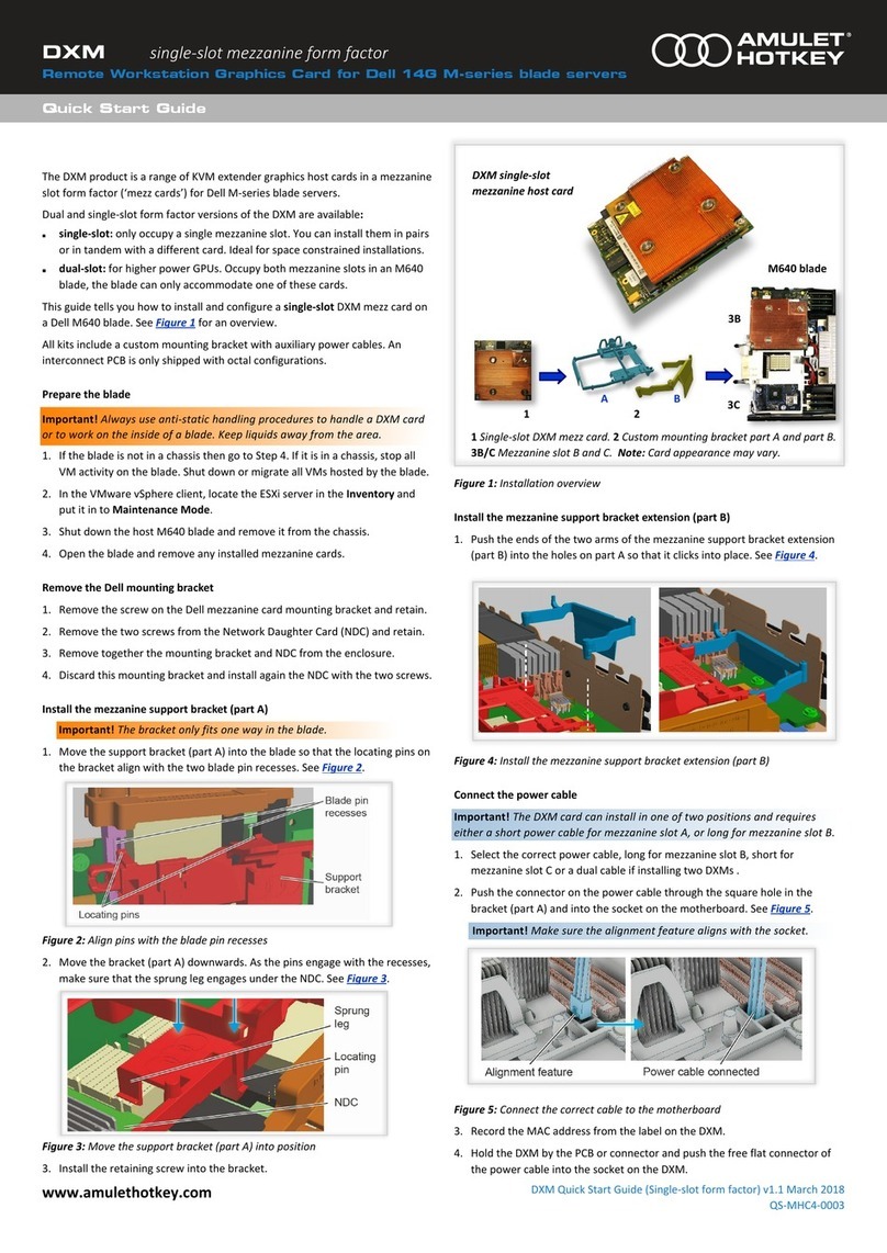
Amulet Hotkey DXP4 User manual

®
Remote WoRkstation GRaphics caRd
User manUal
DXP4 and DXP4-M
HB-DXP4-0002
Revision 3.1 July 2017
Passive and Acve Thermal Soluons

Thank you
Thank you from everyone at Amulet Hotkey for purchasing this
product. Much me and energy has gone into making this the
best and most reliable soluon available. We are condent we
have provided a state-of-the-art unit that will provide you with
long and reliable service regardless of the applicaon.
To get the best from this product, follow this manual carefully.
Shipment and product inspecon
Your product was carefully packed prior to despatch to
guarantee safe transit. Make sure you thoroughly examine all
packaging and contents for signs of physical damage before use.
If any damage has occurred, nofy the shipping company and
your supplier immediately. Otherwise, claims for damage or
replacement may not be granted.
Retain the original packaging for use in the event that the
equipment has to be stored, shipped or returned for service.
If you choose to dispose of the packaging, please do so in an
environmentally friendly fashion.
Technical support
If you have further quesons , do not hesitate to contact
Amulet Hotkey technical support for expert assistance:
EMEA
+44 (0)20 7960 2400
eurosupport@amulethotkey.com
N America
+1 (212) 269 9600
ussupport@amulethotkey.com
South America
latamsupport@amulethotkey.com
Asia Pacic
+61 409 930 884
apsupport@amulethotkey.com
Or look at the resources page on our website:
hps://resources.amulethotkey.com/resources.
CAUTION
To prevent damage to the DXP4:
• install in accordance with these instrucons;
• always turn o and unplug the host computer
before handling the DXP4;
• always use appropriate an-stac handling
procedures when handling the DXP4;
• only use the DXP4 within an enclosed
computer case. Do not operate an opened
computer with a DXP4 installed;
• only use aachments and accessories
approved by Amulet Hotkey;
• do not expose this appliance to moisture;
• do not place objects lled with liquids on or
near the appliance;
• clean the product only with a dry cloth;
• refer all servicing to qualied personnel.
WARNING
• The heat sink on the DXP4 card can get
hot when in use. Wait for it to cool before
handling the card.
©2017 Amulet Hotkey Ltd. All rights reserved.
The informaon contained in this document represents the current view of Amulet Hotkey® as of the date of publicaon. Because Amulet Hotkey must respond to
changing market condions, it should not be interpreted to be a commitment on the part of Amulet Hotkey, and Amulet Hotkey cannot guarantee the accuracy of any
informaon presented aer the date of publicaon. Secons of this document are reproduced with the kind permission of Teradici®Corp. This document is for informa-
onal purposes only. Amulet Hotkey make no warranes, express, implied or statutory, as to the informaon in this document. Complying with all applicable copyright
laws is the responsibility of the user. Without liming the rights under copyright, no part of this document may be reproduced, stored in or introduced into a retrieval
system, or transmied in any form or by any means (electronic, mechanical, photocopying, recording, or otherwise), or for any purpose, without express wrien per-
mission from Amulet Hotkey. Amulet Hotkey may have patents, patent applicaons, trademarks, copyrights, or other intellectual property rights covering subject maer
in this document. Except as expressly provided in any wrien license agreement from Amulet Hotkey, the furnishing of this document does not give you any license to
these patents, trademarks, copyrights, or other intellectual property. Teradici, PC-over-IP, and PCoIP are registered trademarks of Teradici Corporaon. VMware and View
are registered trademarks of VMware Corp. Amulet Hotkey and ‘soluons you can bank on’ are trademarks of Amulet Hotkey Ltd. The names of actual companies and
products menoned herein may be the trademarks of their respecve owners.
Remote Workstation Graphics Card
Page 2
LASER SAFETY
The DXP4-M may be ed with SFP network
modules that contain Class 1 lasers. The SFP
module emits invisible radiaon which can cause
harm if installed or serviced incorrectly. Follow
the guidelines below:
Warning: Class 1 laser product.
Warning: Invisible laser radiaon can be
emied from the aperture of the SFP port
when no bre is connected. To avoid exposure
to laser radiaon, do not stare into open
apertures.
Warning: Only trained and qualied personnel
may install, replace, or service this equipment.

FCC Noce
This device complies with part 15 of the FCC Rules. Operaon is subject to the following
two condions: (1) This device may not cause harmful interference, and (2) this device must
accept any interference received, including interference that may cause undesired operaon.
Title 47, Part 15 (47 CFR 15) of the Federal Communicaons Commission (FCC) Rules and
Regulaons establishes Radio Frequency (RF) emission limits for unlicensed emissions to
provide an interference-free radio frequency spectrum. Many electronic devices, including
computers, generate RF energy incidental to their intended funcon and are, therefore,
covered by these rules. These rules place computers and related peripheral devices into
two classes, A and B, depending upon their intended installaon. Class A devices are those
that may reasonably be expected to be installed in a business or commercial environment.
Class B devices are those that may reasonably be expected to be installed in a residenal
environment (personal computers, for example). The FCC requires devices in both classes to
bear a label indicang the interference potenal of the device as well as addional operang
instrucons for the user. A label on the device shows which class (A or B) the equipment falls
into. Class B devices have an FCC logo or FCC ID on the label. Class A devices do not have an
FCC logo or FCC ID on the label.
The DXP4 has been tested and found to comply with the limits for a Class A digital device,
as dened by Part 15 of the FCC Rules. These limits are designed to provide reasonable
protecon against harmful interference when the equipment is operated in a commercial
environment. This equipment generates, uses, and can radiate radio frequency energy and,
if not installed and used in accordance with the instrucons, may cause harmful interference
to radio communicaons. Operaon of this equipment in a residenal area is likely to cause
harmful interference, in which case the user will be required to correct the interference at
their own expense.
EU Noce
• This product complies with EMC Direcve 2014/30/EU and the Low Voltage Direcve
2014/35/EU. Conformity is shown by compliance with the applicable requirements of
the following documents:
• EN 55032 (CISPR 32) (Class A) - Emissions
• EN 55024 (IEC 61000-4-2,3,4,5,6,8,11) - Immunity
• EN 61000-3-2 (IEC 61000-3-2) - Power Line Harmonics
• EN 61000-3-3 (IEC 61000-3-3) - Power Line Flicker
• EN 60950 (IEC 60950) - Product Safety
Cauon:!
This equipment is compliant with Class A of CISPR 32. In a residenal environment
this equipment may cause radio interference.
Health and Safety Information
www.amulethotkey.com | Page 3

Remote Workstation Graphics Card
Page 4
Contents
1. Before you start ................................... 9
1.1 DXP4 models ............................................ 9
1.1.1 Network soluons ............................................ 9
1.1.2 Thermal soluons............................................. 9
1.1.3 Terminology...................................................... 9
1.2 Auxiliary power requirements ................. 9
1.3 SFP modules............................................. 9
1.4 IP and MAC addresses.............................. 9
1.5 Wake on LAN and remote power cycling10
1.5.1 WoL supported ...............................................10
1.5.2 WoL not supported - RPC cable required .......10
2. Your DXP4 .......................................... 11
2.1 I/O bracket features ............................... 11
2.2 I/O bracket status LEDs .......................... 12
2.2.1 Key.................................................................. 12
2.2.2 STATUS (link) LED ............................................12
2.2.3 Network ACTIVITY and SPEED status LEDs ....13
2.3 BSM status indicaon ............................ 13
2.4 Recessed buon operaons .................. 13
2.4.1 While the DXP4 is starng up .........................13
2.4.2 When the DXP4 is powered up.......................13
2.5 DisplayPort socket (Acve Soluon only)
............................................................... 13
2.6 Internal card connecons ...................... 14
3. Set up the host card ........................... 15
3.1 STEP 1: Prepare the PC, Workstaon or
server ..................................................... 15
3.2 STEP 2: Install the DXP4 ........................ 15
3.3 STEP 3: Connect oponal equipment .... 15
3.3.1 Connect auxiliary power (Oponal) ...............15
3.3.2 Connect Remote Power Cable (Oponal).......16
3.3.3 Connect SFP module (DXP4-M only) .............. 16
3.4 STEP 4: Connect the DXP4 to the network
............................................................... 16
3.5 STEP 5: Complete the installaon .......... 16
3.6 STEP 6: Connect a zero client to the DXP4
............................................................... 17
3.6.1 Connect to a DXP4 using SLP Discovery..........17
3.7 STEP 7: Change the default password.... 17
3.8 Set up is complete.................................. 17
4. How to install dual DXP4 cards........... 19
4.1 Before you install the DXP4s .................. 19
4.2 Install the rst DXP4............................... 19
4.3 Install the second DXP4 ......................... 20
4.4 Connect to the network......................... 20
4.5 Connect the zero clients to the host PC. 20
4.6 Check the other Ethernet connecon.... 20
5. Install a DXP4 with a network expansion
card (DXEC) ........................................ 21
5.1 Before you install a network expansion
card ........................................................ 21
5.2 Install the DXP4...................................... 21
5.3 Install the network expansion card........ 21
5.4 Connect the zero client to the host PC .. 21
5.5 Check the DXP4 Ethernet connecon .... 21
6. Introducon to PCoIP......................... 23
6.1 What is PCoIP?....................................... 23
6.1.1 Host rendering................................................23
6.1.2 Mul-codec display processing ......................24

Contents
www.amulethotkey.com | Page 5
8. Manage the network ......................... 31
8.1 Consider network bandwidth
requirements ......................................... 31
8.1.1 Factors aecng bandwidth...........................31
8.1.2 What happens when available bandwidth is
exceeded ........................................................ 31
8.2 Dual redundant network connecons ... 31
8.3 Choose a connecon broker if required 32
8.3.1 Role of the connecon broker........................32
8.3.2 Specify the connecon broker........................32
8.3.3 Using the connecon broker ..........................32
9. Addional informaon....................... 33
9.1 Make sure the DXP4 rmware is up to
date ....................................................... 33
9.1.1 Check the BSM rmware on an individual host
card................................................................. 33
9.1.2 How to remove the DXP4 ...............................33
9.2 Fan maintenance (Acve Thermal
Soluon)................................................. 33
9.2.1 Fan fault LED indicaon (rmware dependent)
........................................................................ 33
9.3 Check the funcon of the Ethernet
connecon in an octal conguraon ..... 34
10. Technical specicaons...................... 35
10.3.1 Warranty......................................................... 35
10.3.2 Technology .....................................................35
10.3.3 Environment ................................................... 36
6.1.3 Dynamically adapts to network condions ....24
6.2 About PCoIP hosts.................................. 24
6.2.1 Host funcon.................................................. 24
6.2.2 Host types.......................................................24
6.3 About PCoIP zero clients........................ 24
6.3.1 Funconality................................................... 24
6.3.2 Data handling .................................................24
6.4 Benets of PCoIP zero clients................. 24
6.4.1 Increased security ..........................................24
6.4.2 Low maintenance ...........................................25
6.4.3 Cost savings ....................................................25
6.5 PCoIP management tools....................... 25
6.5.1 PCoIP Management Console ..........................25
6.5.2 Administrave Web Interface (AWI)...............26
6.5.3 On Screen Display (OSD)................................. 26
7. Set up a PCoIP session........................ 27
7.1 Power up the zero client ........................ 27
7.2 Types of PCoIP session .......................... 27
7.2.1 Auto Detect .................................................... 27
7.2.2 Connect directly to a specied host ..............27
7.2.3 Connect to a choice of hosts using SLP
Discovery ........................................................28
7.2.4 PCoIP Connecon Manager............................28
7.2.5 PCoIP Connecon Manager + Auto-Logon .....28
7.2.6 Connect using VMware View .........................28
7.2.7 Connect with View Connecon Server and
Auto-Logon.....................................................28
7.2.8 Connect using a connecon broker................28
7.3 Set an automac connecon ................. 29
7.4 Disconnect from a host PC or virtual
desktop .................................................. 29
7.5 Further informaon ............................... 29

Remote Workstation Graphics Card
Page 6
List of gures
Figure 1:Front panel features�������������������������������������������������������������������������������������������������������������������������� �11
Figure 2:STATUS (link) LED������������������������������������������������������������������������������������������������������������������������������� �12
Figure 3:��������������������������������������������������������������������������13
Figure 4:������������������������������������������������������������������������������������������������������������������������������
Figure 5:����������������������������������������������������������������������������������������������������������������������� �15
Figure 6:��������������������������������������������������������������������������������������������������������������� �15
Figure 7: ������������������������������������������������������������������������������������������������������������������������ �16
Figure 8:������������������������������������������������������������������������������������������������������������������������ �16
Figure 9:������������������������17
Figure 10: ���������������������������������������������������������������������������������������������������������� �19
Figure 11:��������������������������������������������������������������������������������������������������������������������������� �19
Figure 12: ���������������������������������������������������������������������������������������������
Figure 13: ���������������������������������������������������������������������������������������������������������������������
Figure 14: ������������������������������������������������������������������������������������������������������������������������ �23
Figure 15: �����������������������������������������������������������������������������������������25
Figure 16: �������������������������������������������������������������������������������������������������������� �26
Figure 17: ������������������������������������������������������������������������������������������������������������������������ �26
Figure 18:������������������������������������������������������������������������������������������������������ �27
Figure 19:���������������������������������������������������������������������������������������������������������27
Figure 20:���������������������28

Contents
www.amulethotkey.com | Page 7
List of tables
Table 1: �������������������������������������������������������������������������������������������������������������������12
Table 2: ����������������������������������������������������������������������������������������������������������� �13
Table 3: ����������������������������������������������������������������������������������������������������������������13
Table 4:������������������������������������������������������������������������������������������������������������ �25
Table 5: �����������������������������������������������������������������������������������������������������������31
Table 6: ������������������������������������������������������������������������������������35
Table 7:���������������������������������������������������������������������������������������������������������������36
Figure 21: ����������������������������������������������������������������������������������������������������28
Figure 22: ����������������������������������������������������������������������������������28
Figure 23: ���������������������������������������������������������������������������������������������������29
Figure 24:����������������������������������������������������������������������������������������������������������29
Figure 25: �����������������������������������������������������������������������������������������������������������������

Remote Workstation Graphics Card
Page 8

www.amulethotkey.com | Page 9
Before you start 1
1. Before you start
This manual is for the Amulet Hotkey DXP4 and DXP4-M Remote
Workstaon Graphics Cards. Before you install the DXP4 or
DXP4-M, make sure you read the following informaon.
The Amulet Hotkey DXP4 is a PC-over-IP (PCoIP®) host with
an integrated quad-video GPU. It is an ideal host soluon for
remote desktop applicaons that require pixel perfect video
across mulple monitors.
1.1 DXP4 models
The DXP4 is a PCI express (PCIe) card available with the following
variaons:
1.1.1 Network soluons
DXP4: The standard card has a single RJ45 network port;
DXP4-M: This model has a single network port that accepts
either a ber or copper SFP module (see 1.3 and Figure 1).
1.1.2 Thermal soluons
Both the DXP4 and the DXP4-M are available for dierent PC,
server or Workstaon cooled environments:
• Acve Thermal Soluon: the card is cooled via an on-board
fan;
• Passive Thermal Soluon: the card uses a large heatsink and
relies on a temperature-controlled environment provided by
the PC or server.
Important!
Make sure you choose the correct card type for
your enclosure.
Note: Some GPUs are not available in both thermal soluons.
See 10. Technical specicaons for more details. Both thermal
soluons are installed and congured in the same way.
1.1.3 Terminology
The general term ‘host card’ is used throughout this manual to
describe all network and thermal variants.
1.2 Auxiliary power requirements
Important!
The host card may require an auxiliary power
connecon from the power supply depending on the GPU
power requirements and the power supply from the mother-
board. See 3.3.1 Connect auxiliary power (Oponal).
1.3 SFP modules
Amulet Hotkey can provide a range of suitable SFP modules,
including 1Gbps and 100Mbps ber SFP modules for single or
mul-mode ber and copper SFP modules with RJ45 connectors.
See the Amulet Hotkey SFP Modules Datasheet for details of
currently available modules.
Be aware that SFP modules have diering specicaons, and
the distances over which they can drive a signal can vary. This
especially applies to ber SFP modules.
Important!
The DXP4-M only supports certain models of SFP
module. If in doubt, contact Technical Support for advice.
1.4 IP and MAC addresses
Before you set up a host card, make a note of these details:
• MAC and IP address of the remote PCoIP host;
• MAC and IP address of the zero client.
You will nd the MAC address informaon wrien on the
underside of the zero client and on the conguraon record/
serial number label of the remote host. You can also use the AWI
(see 6.5.2) to nd the MAC addresses
If your network uses DHCP, the host and zero client obtain
their IP addresses from the DHCP server. If no DHCP server is
available, the host and zero client me out aer approximately
two minutes and adopt the following default IP addresses:
• Zero client: 192.168.1.50
• Host card: 192.168.1.100

Remote Workstation Graphics Card
Page 10
1.5 Wake on LAN and remote power cycling
By default, the DXP4 supports Wake on LAN (WoL), allowing
users to wake up the host from standby. To power down or
power cycle the host computer from a remote zero client
requires the installaon of a Remote Power Cable (RPC).
There are two opons for seng up WoL depending on whether
your system supports it directly or not:
• WoL supported;
• WoL not supported - RPC cable required.
1.5.1 WoL supported
Most computers support WoL, though it may not be enabled by
default. When WoL is enabled on the host computer, end-users
can wake up the host computer automacally when they
connect to it from a remote zero client.
WoL requires appropriate BIOS, network card and operang
system support. Refer to your host computer documentaon for
details about enabling this feature.
Example: To enable WoL for Windows 8 computers, you must
edit the Magic Packet and power management properes of
the appropriate network adapter.
1.5.2 WoL not supported - RPC cable required
For an alternave setup, you can install a Remote Power Control
(RPC) cable assembly to interpose the DXP4 between the host
computer’s power switch and the associated motherboard
header (see 3.3.2 Connect Remote Power Cable (Oponal)).
Specically, connect the RPC cable to the RPC socket on the
DXP4 (see 2.6 Internal card connecons).
This allows users to power cycle the host computer from a
remote zero client. Unlike the WoL setup, the RPC setup also
allows users to power cycle, power up and fully power down the
remote PC (for example, if it has blue-screened).
Aer connecng the RPC cable assembly:
• users of Amulet Hotkey DXR zero clients can press the RPC
switch to power cycle the host computer;
• users of Amulet Hotkey DXZ zero clients can use the On
Screen Display (OSD) to power cycle the host computer.

www.amulethotkey.com | Page 11
your DXP4
2. Your DXP4
The DXP4 has various LEDs, sockets and jumper pins. These are
described in the secons that follow.
2.1 I/O bracket features
The I/O bracket for the DXP4 includes four LEDs, a network port,
a DisplayPort connector (Acve Soluon), and a recessed buon.
See Figure 1 for the following descripon:
1. STATUS LED: Shows the network type and status. See 2.2.2
for details.
2. Int Fn LED: Reserved for future use.
3. Recessed buon: Insert a paper-clip into the hole to press
the recessed buon. See 2.4 for details.
4. DisplayPort connector: Use this to connect a local monitor
directly to the host computer. See 2.5 for details.
5. Network SPEED LED: Indicates the network speed. See 2.2.3
for details.
6. Network ACTIVITY LED: In normal operaon, this LED shows
network acvity. It can also show progress for rmware
updates. See 2.2.3 for details.
7. Network port: The standard DXP4 has an RJ45 socket. The
DXP4-M has a socket that accepts an SFP module. See the
SFP Datasheet for details of modules available separately
from Amulet Hotkey.
1 2 3 5 6 74
DXP4-M: Active Thermal Solution
DXP4: Passive Thermal Solution
2
Figure 1: Front panel features

Remote Workstation Graphics Card
Page 12
2.2 I/O bracket status LEDs
The status LEDs on the I/O bracket (see Figure 1) show the status
of the network connecon including:
• the connecon type and speed;
• the current network acvity;
• the status of the PCoIP connecon to a zero client.
There are four LEDs on the front panel:
• INT FN LED (not used);
• STATUS (link) LED;
• ACTIVITY (PCoIP) status LED;
• and the SPEED status LED.
See Figure 1, Figure 2 and Figure 3.
2.2.1 Key
The tables in this secon use the following convenons:
• Color - LED is on steady;
• Flash - LED is on and o evenly;
• Blink - LED is on more than o;
• Wink - LED is o more than on.
2.2.2 STATUS LED
The host card has a STATUS (link) LED to indicate the type and
status of the network connecon.
STATUS (link) LED
Figure 2: STATUS (link) LED
The STATUS LED displays the following indicaons.
LED status Meaning
O No PCoIP link is established
Green wink Copper network connecon is detected (SFP
module or RJ45). Network link is not in session
Green Copper network connecon with link
established (SFP module or RJ45)
White ash BSM status indicaon. See 2.3.
Red wink Minor card error (for example cooling fan not
working).
Red ash Major card error
Red Power error
For SFP Modules only:
Green wink SFP copper network connecon is available but
not in session (or no SFP module inserted)
Blue wink SFP ber network connecon is available but
not in session (or no SFP module inserted)
Blue SFP ber module detected; connected to
network
Green SFP copper module detected; connected to
network
Cyan wink SFP module is not recognized
Table 1:

Your DXP4
www.amulethotkey.com | Page 13
2. SPEED status LED
Status Meaning
O No network connecon
Amber 100 Mbit/s connecon
Green 1 Gbit/s connecon
White ash BSM status indicaon. See 2.3.
Table 3:
2.3 BSM status indicaon
When power is applied to the Board Support Micro-controller
(BSM) or when the BSM is reset (for example, aer a successful
rmware update), all LEDs simultaneously ash white (or very
pale blue) for one second.
2.4 Recessed buon operaons
2.4.1 While the DXP4 is starng up
• press the buon to restore the DXP4 factory sengs.
2.4.2 When the DXP4 is powered up
• A quick press of the buon (less than one second)
toggles a local monitor on or o (Acve Thermal
Soluon only).
• A long press (hold the buon for ve seconds or more)
toggles the Board Support Micro-controller (BSM)
network interface ON or OFF.
When the network interface is ON, you can update DXP4
rmware remotely by transferring a rmware package to
the BSM.
2.5 DisplayPort socket (Acve Soluon only)
Important!
There is no DisplayPort socket on the Passive
Thermal Soluon DXP4, only on the Acve Thermal Soluon.
The local DisplayPort allows you to perform inial setup tasks or
troubleshoot the host computer.
Important!
Press the recessed buon (see 2.4) or unplug the
local monitor before you start a PCoIP session to a remote
zero client.
Note: The DisplayPort video output is dual mode so you can
connect to DisplayPort or DVI-D video inputs on the monitor
using suitable cable adaptors.
2.2.3 Network ACTIVITY and network SPEED LEDs
The host card has two network LEDs, ACTIVITY (link) and SPEED
(see Figure 3) on the rear panel that operate as follows:
SPEED LED ACTIVITY LED
Figure 3:
1. Network ACTIVITY LED
In normal operaon, this LED shows network acvity and
connecon type. It can also show progress for rmware updates.
NORMAL MODE
Status Meaning
O No network connecon
Green Network connecon full duplex; no trac
Green blink Network connecon full duplex; trac detected
Red wink
Fault with Teradici PCoIP: Half duplex
connecon
Warning: A half duplex connecon will severely
limit a user’s experience. PCoIP sessions may
disconnect with large packet losses reported in
the PCoIP connecon stascs.
White ash BSM status indicaon. See 2.3.
FIRMWARE UPDATE MODE
Status Meaning
Amber BSM network port is open and aempng to
obtain a DHCP address
Blue
BSM network port is open and has a valid IP
address (either a DHCP address or the BSM
fall-back address of 192.168.1.75)
Blue wink
BSM update is complete. The BSM network
port is closed. Restart the host computer at a
convenient me to apply the new rmware
Red wink
BSM update failed to complete (the checksum
validaon failed). The BSM network port
is closed. Restart the host computer at a
convenient me to ush the new rmware from
ash memory
White BSM status indicaon. See 2.3.
Table 2:

Remote Workstation Graphics Card
Page 14
3. RPC socket: If required, this socket connects the DXP4 to the
motherboard using a suitable Remote Power Control (RPC)
cable assembly. This connecon may be required to power
cycle the host computer from a remote zero client.
See Wake on LAN and remote power cycling (on page 10)
for details.
4. Inter-card connecon socket: This socket is used to connect
two DXP4s together for a maximum of eight displays (octal
mode), or for connecng the DXEC expansion card.
See 4. How to install dual DXP4 cards and 5. Install a DXP4
with a network expansion card (DXEC) for how to do this.
5. PCIe x8 edge connector: This ×8 connector ts into a PCIe
slot. It is also compable with ×16 slots.
2.6 Internal card connecons
The DXP4 card has several internal sockets and jumpers. These
connecons are not accessible through the mounng bracket.
1. Factory default reset jumper pin: (Jumper is not ed) As
an alternave to using the recessed buon (see 2.1), you can
use this jumper to restore the DXP4 factory sengs. Close
the contacts then power up the host computer.
Before reconguring a DXP4 that has been reset, you must
power down the host computer and remove the jumper.
2. Auxiliary (‘aux’) power socket: These MXM GPUs require a
PCIe connecon to this power socket to funcon correctly.
• NVIDIA K2200M
• NVIDIA M2000M;
• AMD S4000X;
• AMD E6760.
For a list of currently supported MXM GPUs, see Technical
specicaons (on page 35).
5
1
1
2
3
4
2
3
4
5
DXP4: Passive Thermal Solution
DXP4: Active Thermal Solution
Figure 4:

www.amulethotkey.com | Page 15
Install the DXP4
3. Set up the host card
This secon describes how to set up your DXP4. For card
informaon, see 2. Your DXP4.
3.1 STEP 1: Prepare the PC, Workstaon or server
Cauon:!
The host PC must be switched o before you install or
remove the DXP4.
1. Turn o the host computer.
2. Unplug the power cable.
3. Wait at least 60 seconds to allow the internal power rails to
fully discharge.
4. Remove any covers to provide access to the PCIe sockets.
3.2 STEP 2: Install the DXP4
Cauon:!
Make sure you wear a wriststrap and follow an-stac
precauons before you handle any cards, or work on the PC.
1. Make a note of the MAC address on the label of the DXP4.
You may need this when pairing the DXP4 to a zero client.
2. Carefully install the DXP4 into a free ×8 or ×16 PCIe socket.
See Figure 5. Secure in place.
3
x16 PCIe slotx1 PCIe slot x4 PCIe slot
3.3 STEP 3: Connect oponal equipment
3.3.1 Connect auxiliary power (Oponal)
Important!
The DXP4 card may require connecon to
auxiliary power within the host PC or Workstaon depending
on your system and the on-board GPU requirements.
1. If required, connect the host’s PCIe power cable to the
auxiliary PCIe power socket. See Figure 6.
PCIe cable
connected
Figure 6:
Figure 5:

Remote Workstation Graphics Card
Page 16
3.3.2 Connect Remote Power Cable (Oponal)
Important!
Some workstaons may require a RPC to
implement remote power-cycling. See Wake on LAN and
remote power cycling (on page 10).
Note: The DXP4 comes with a generic RPC cable assembly.
However, we recommend that you contact Amulet Hotkey
technical support to make sure this is suitable for your needs.
1. If required, connect the RPC cable between the motherboard
and the RPC socket on the DXP4. See Figure 7.
2 1
3
4
Figure 7:
Key to Figure 7.
1. RPC assembly. 2. RPC socket on the DXP4 3. Motherboard
power switch header on the host computer 4. Front panel power
switch on the host computer
3.3.3 Connect SFP module (DXP4-M only)
1. Fit the required SFP module into the DXP4-M network socket.
This socket accepts a copper or bre SFP module. The module
can be 1 Gbit/s or 100 Mbit/s. See the SFP modules datasheet
for more details of available modules.
Figure 8:
3.4 STEP 4: Connect the DXP4 to the network
1. Connect a network cable to the DXP4.
3.5 STEP 5: Complete the installaon
1. Re-assemble the host computer, make sure all blanking
plates are ed, and reconnect the power cable.
2. Restart the computer.
The operang system detects the DXP4 and locates the
appropriate drivers.
3. Make sure you have the appropriate driver for the MXM GPU
on your DXP4. The latest drivers are available on our website.
For further help, contact the GPU supplier or Amulet Hotkey
technical support.
4. Install the driver on the host computer.
5. (Oponal, for the Acve Soluon only) If required, connect
a local monitor to the DXP4 DisplayPort to complete the host
computer setup.
6. (Oponal) If you need to install a second DXP4 see 4. How to
install dual DXP4 cards on page 19.
7. (Oponal) If you need to install a network extender card see
5. Install a DXP4 with a network expansion card (DXEC) on page
21.
Note: You may not install dual DXP4s and a network extender
card in the same installaon.

Install the DXP4
www.amulethotkey.com | Page 17
3.6 STEP 6: Connect a zero client to the DXP4
1. Install and power up a zero client.
If you are not sure how to do this, see the relevant Amulet
Hotkey user manual or Quick Start Guide for the zero client.
Aer powering up the zero client, you are ready to establish a
new PCoIP session.
The zero client connects to the DXP4 via the network port.
Note: We recommend reading 6. Introducon to PCoIP rst if
you are not already familiar with the concept of PCoIP.
3.6.1 Connect to a DXP4 using SLP Discovery
Important!
This is one method you can use to quickly
connect your zero client to a host. For a detailed descripon
of all connecon methods, see 7. Set up a PCoIP session.
If the zero clients and PCoIP hosts reside on the same subnet,
you can use the Direct to Host + SLP session connecon type to
discover available PCoIP hosts on the subnet.
You must know the IP address (or MAC address) of the PCoIP
host that you want to connect to.
1. Select the Direct to Host + SLP Host Discovery session
connecon type from the drop down list.
Figure 9:
2. Select the host you want and click OK.
If the zero client successfully connects to the host, the front
panel PCoIP status LED illuminates green to indicate an acve
session.
3. (Oponal) You can also set the Enable Auto-Reconnect in the
advanced sengs to remember the last connected PCoIP host.
Note: You must also congure a Direct from Client session
connecon type on the host.
3.7 STEP 7: Change the default password
1. For security, we recommend that you change the default
password for your DXP4 at the earliest possibility.
Important!
You must enter a password before changing
the conguraon of host cards and zero clients. The factory
pre-set password for all Amulet Hotkey host cards and zero
clients is ahkdante.
3.8 Set up is complete
If you wish to read further about network consideraons, refer
to 8. Manage the network.
For any conguraon or deployment issues refer to
9. Addional informaon or contact Technical Support
department (see contact details at the start of this manual).

Remote Workstation Graphics Card
Page 18

www.amulethotkey.com | Page 19
Install Dual DXP4 carDs 4
4. How to install dual DXP4 cards
To set up an eight display conguraon (octal mode), install two
DXP4s and connect them with two zero clients.
The informaon below tells you how to install two DXP4s into
a standard PC. There may be slight variaons for other PCs or
workstaons.
Note: There are two possible network soluons. See Figure 10.
A. Two DXP4 cards with independent network links
B. Two DXP4 cards with a single network link, linked internally.
Figure 10:
4.1 Before you install the DXP4s
Cauon:!
Do not install dual DXP4 cards onto a single network
unless that network supports Spanning Tree Protocol (STP).
1. Make sure that the PC power cable is unplugged before you
install the DXP4s.
2. Make sure that the power supply is ed with two PCIe
power connectors that can provide supplemental PCIe power to
the DXP4.
3. Make sure you wear a wriststrap or follow suitable an-stac
precauons before you handle any cards or work on the PC.
4. Make a note of the MAC address on the label on each DXP4.
Example: MAC: 00 17 FD 46 03 56
4.2 Install the rst DXP4
You will need one interlink cable to connect the DXP4 cards.
1. (For network soluon B only) Connect one end of the
interlink cable to the connector on the rst DXP4.
2. Connect one of the two available PCIe power connectors to
the connector on the rst DXP4.
3. Install the rst DXP4 into any free x8 or x16 PCIe slot in the
host PC. See Figure 11.
x16 PCIe slotx1 PCIe slot x4 PCIe slot
Figure 11:

Remote Workstation Graphics Card
Page 20
ACTIVITY
LED
INT FN
LED
STATUS
LED
SPEED
LED
Figure 13:
3. Connect a zero client to the rst DXP4.
Example: Set the connecon type to SLP and Host Discovery
and select the MAC address from the available list of hosts on
each zero client.
4. Connect a zero client to the second DXP4.
4.6 Check the other Ethernet connecon
1. Make sure that eight heads of video are present.
2. Disconnect the Ethernet cable from the rst DXP4 and
connect to the second DXP4.
When you swap the cable from the rst DXP4 to the second
DXP4 the zero clients temporarily indicate a loss of signal and
then recover the connecon.
The SPEED LED lights AMBER and ON, the ACTIVITY LED
ashes GREEN on the DXP4 connected to the Ethernet cable.
4.3 Install the second DXP4
1. (For network soluon B only) Connect the free end of the
interlink cable to the second DXP4.
2. Connect the second PCIe power connector to the second
DXP4.
3. Install the second DXP4 into any free x8 or x16 PCIe slot in
the host PC.
PCIe power
connector
DXP4s
Interlink
cable
connector
Interlink
cable
Figure 12:
4. Make sure the DXP4 mounng bracket is xed securely in the
PC.
4.4 Connect to the network
1. For network soluon A: connect an Ethernet cable to one of
the DXP4s.
2. For network soluon B: connect an Ethernet cable to both
DXP4s.
4.5 Connect the zero clients to the host PC
1. Connect the power cable to the PC
2. Turn on the host PC and wait for both DXP4s to power up.
See Figure 13.
The STATUS and INT FN LEDs are GREEN and ash on both
DXP4s.
The ACTIVITY LED ashes GREEN to show network acvity,
the SPEED LED is AMBER (or GREEN depending on link speed)
and ON on the DXP4 connected to the Ethernet cable.
The ACTIVITY and SPEED LEDs are OFF on the DXP4 with no
Ethernet cable.
This manual suits for next models
1
Table of contents
Other Amulet Hotkey Video Card manuals
Popular Video Card manuals by other brands

Gigabyte
Gigabyte GV-R587SO-1GD user manual

Advanced Micro Computers
Advanced Micro Computers AVC8000nano Hardware reference manual

IEI Technology
IEI Technology HDC-301MS-R10 Quick installation guide

Gainward
Gainward GTX 560SE 1024MB datasheet

ATI Technologies
ATI Technologies All-In-Wonder Radeon 9000 Card user guide

Gigabyte
Gigabyte GV-RX80256DE user manual

Diamond Multimedia
Diamond Multimedia Radeon GX700PCIE256-CN Specification sheet

S3 Graphics
S3 Graphics CHROME 400 Series user guide

NEC
NEC N8116-29 user guide

Nvidia
Nvidia Quadro Workstation user guide

Gigabyte
Gigabyte GV-R587OC-1GD user manual

ATI Technologies
ATI Technologies RADEON X800 PCIe Series user guide