manuals.online logo
Brands
  1. Home
  2. •
  3. Brands
  4. •
  5. AMX
  6. •
  7. Controllers
  8. •
  9. AMX AXB-VOL3 Guide

AMX AXB-VOL3 Guide

QUICK START GUIDE
AXB-VOL3 3-Channel Volume Controller
Overview
The AXB-VOL3 (FG5756) controls three audio volume channels. Each line-level channel,
opto-isolated from system ground, can be configured for balanced or unbalanced line
operation. It is programmable for 128 steps of audio level, audio mute, variable ramp
speed and level presets.
Specif ications
Installation
Setting the DEVICE DIP Switch
Note: Use the DIPSwitch 2.0 application available for free download from AMX to quickly
figure out DIP Switch settings for all types of DIP Switches.
Set the device number on DEVICE DIP switch, located on the front of the AXB-VOL3. The
device can be 1 of the 255 devices in an Axcess control system. The device number
must match the device assignment in the Axcess program. Device numbers are
assigned into the following three segments:
•Cards 1 through 95
•Boxes 96 through 127
•Panels 128 through 255
Set the device number by setting the device DIP switches. The device number is the
total of all of the switches in the ON position, and take effect by cycling the power.
Wiring
Preparing and Connecting Captive Wires
1. Strip 0.25 inch of wire insulation off all wires.
2. Insert each wire into the appropriate opening on the connector according to the
wiring diagrams and connector types described in this section.
3. Tighten the screws to secure the wires. Do not tighten the screws excessively;
doing so may strip the threads and damage the connector.
Wiring Guidelines
The interface requires a 12 VDC power to operate properly. The interface uses a PS2.8
power supply. The Central Controller supplies power via the AxLink cable or external 12
VDC power supply.
The maximum wiring distance between the Central Controller and interface is
determined by power consumption, supplied voltage, and the wire gauge used for the
cable.
The table below lists wire sizes and maximum lengths allowable between the VOL3 and
Central Controller. The maximum wiring lengths for using
AxLink power are based on a minimum of 13.5 volts available at the Central Controller’s
power supply.
AxLink Connector
Install the AxLink data/power bus wiring as shown in FIG. 2.
Volume Channels 1 - 3 Connectors
Volume channels 1 - 3 can be wired for unbalanced or balanced line operation, as
shown in FIG. 3.
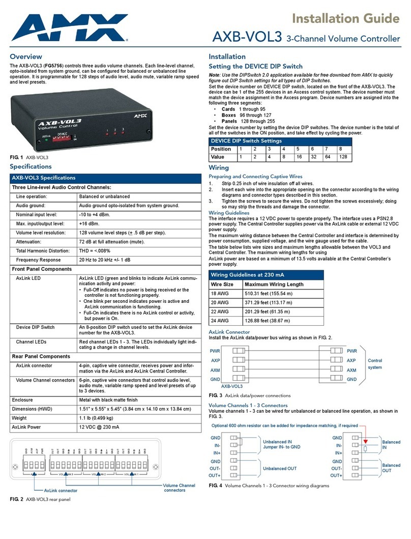
FIG. 1 AXB-VOL3
AXB-VOL3 SPECIF ICATIONS
Three Line-level Audio Control Channels:
Line operation: Balanced or unbalanced
Audio ground: Audio ground opto-isolated from system ground.
Nominal input level: -10 to +4 dBm.
Max. input/output level: +16 dBm.
Volume level resolution: 128 volume level steps (+ .5 dB per step).
Attenuation: 72 dB at full attenuation (mute).
Total Harmonic Distortion: THD = <.008%
Frequency Response 20 Hz to 20 kHz +/- 1 dB
Front Panel Components
AxLink LED AxLink LED (green and blinks to indicate AxLink
communication activity and power:
• Full-Off indicates no power is being received or the
controller is not functioning properly.
• One blink per second indicates power is active and AxLink
communication is functioning.
• Full-On indicates there is no AxLink control or activity, but
power is On.
Device DIP Switch An 8-position DIP switch used to set the AxLink device
number for the AXB-VOL3.
Channel LEDs Red channel LEDs 1 - 3. The LEDs individually light indicating
a change in channel levels.
Rear Panel Components
AxLink connector 4-pin, captive wire connector, receives power and
information via the AxLink and AxLink Central Controller.
Volume Channel
connectors
6-pin, captive wire connectors that control audio level, audio
mute, variable ramp speed and level presets of up to 3
devices.
Enclosure Metal with black matte finish
Dimensions (HWD) 1.51" x 5.55" x 5.45" (3.84 cm x 14.10 cm x 13.84 cm)
Weight 1.1 lb (0.499 kg)
AxLink Power 12 VDC @ 230 mA
FIG. 2 AXB-VOL3 REAR PANEL
GND
AXP
AXM
PWR
OUT
OUT
GND
IN
IN
GND
IN
OUT
OUT
GND
GND
IN
OUT
IN
GND
OUT
IN
GND
AXlink VOL CHAN 3 VOL CHAN 2 VOL CHAN 1
Volume Channel
connectors
AxLink connector
DEVICE DIP SWITCH SETTINGS
Position 12345678
Value 1248163264128
WIRING GUIDELINES AT 230 MA
Wire Size Maximum Wiring Length
18 AWG 510.31 feet (155.54 m)
20 AWG 371.29 feet (113.17 m)
22 AWG 201.29 feet (61.35 m)
24 AWG 126.88 feet (38.67 m)
FIG. 3 AXLINK DATA/POWER CONNECTIONS
FIG. 4 VOLUME CHANNELS 1 - 3 CONNECTOR WIRING DIAGRAMS
PWR
AXP
AXM
GND
PWR
AXP
AXM
GND
AXB-VOL3
Control
system
GND
IN-
IN+
GND
OUT-
OUT+
Unbalanced IN
Jumper IN- to GND
Unbalanced OUT
GND
IN-
IN+
GND
OUT-
OUT+
Balance
IN
Balance
OUT
Optional 600 ohm resistor can be added for impedance matching, if required
© 2015 Harman. All rights reserved. Axcess, AMX, AV FOR AN IT WORLD, HARMAN, and their respective logos are registered trademarks of
HARMAN. Oracle, Java and any other company or brand name referenced may be trademarks/registered trademarks of their respective companies.
AMX does not assume responsibility for errors or omissions. AMX also reserves the right to alter specifications without prior notice at any time.
The AMX Warranty and Return Policy and related documents can be viewed/downloaded at www.amx.com.
3000 RESEARCH DRIVE, RICHARDSON, TX 75082 AMX.com | 800.222.0193 | 469.624.8000 | +1.469.624.7400 | fax 469.624.7153
AMX (UK) LTD, AMX by HARMAN - Unit C, Auster Road, Clifton Moor, York, YO30 4GD United Kingdom • +44 1904-343-100 • www.amx.com/eu/
93-5756-01 REV: B
Last Revised: 11/03/2015
Programming
The following sections list Axcess programming commands used with the AXB-VOL3.
Channel Settings Commands
Use the AXB-VOL3 channel settings listed for ramp up, ramp down and mute
operations.
Note: Ramping a volume channel while the mute channel is on will NOT automatically
turn off the mute channel (will not restore) but the ramping will still occur and the volume
change will be noticed when the mute channel is turned off. For setting ramp rates and
presets, see SEND_COMMAND programming instructions below. For reading current
volume levels and displaying bargraphs see CREATE_LEVEL and SEND_LEVEL
programming instructions. Volume channels 1 through 3 use levels 1 to 3 respectively.
When controlling levels, such as with an active bargraph, there is no LED indication of
volume changes.
Levels
•1=Output#1
•2=Output#2
•3=Output#3
SEND_COMMANDs
System SEND_COMMANDs are stored in the Axcess Control System.
AXB-VOL3 CHANNEL SETTING COMMANDS
Channel Description Channel Description
1 Ramps channels 1 and 2 up. 7 Ramps channel 2 up.
2 Ramps channels 1 and 2 down. 8 Ramps channel 2 down.
3 Mutes channels 1 and 2. 9 Mutes channel 2.
4 Ramps channel 1 up. 10 Ramps channel 3 up.
5 Ramps channel 1 down. 11 Ramps channel 3 down.
6 Mutes channel 1. 12 Mutes channel 3.
AXB-VOL3 SEND_COMMANDS
Command Description
PLT Ramps specified channel(s) from current level to a specified preset level or
percentage at the current rate or optionally in a specified amount of time.
Syntax:
SEND_COMMAND VOL, ’P<output channel 0-3>L
<level 0-255|0-100%>[T<Time 0-255 in tenth second
increments>]’
Variables:
Output Channel = Channel numbers 1, 2 or 3. Output channel 0 = both
channels 1 and 2.
Level = Level number (0-255) or percentage (0-100 percent). Level 0 is
lowest volume (same as mute) and 255 or 100% is maximum volume.
Time = Optional ramp time (0-255) in tenths of a second.
Example 1:
SEND_COMMAND VOL,'P0L50%'
Ramps both channels to 50% mid level volume at the current ramp rate.
Example 2:
SEND_COMMAND VOL,'P1L255T20'
Ramps channel 1 to highest level volume in 2 seconds.
PR Sets the ramp rate of the specified channel(s) where the time is the time to
ramp the full range both down to up and up to down or optionally just down to
up or just up to down.
Syntax:
SEND_COMMAND VOL, 'P<output channel 0-3>R
<ramp rate 0-255 in tenth seconds>[U|D]'
Variables:
Output Channel = Channel numbers 1, 2 or 3. Output channel 0 = both
channels 1 and 2.
Ramp Rate = Sets ramp rate (1-255) for channel commands in tenth
second increments.
U = Optional character sets rate for ramp up.
D = Optional character sets rate for ramp down.
Example 1:
SEND_COMMAND VOL, 'P0R50'
Sets ramp rate of channels 1 and 2 to 5 seconds full range from down to up
and up to down.
Example 2:
SEND_COMMAND VOL, 'P3R50D'
Sets ramp rate of channel 3 to 5 seconds full range from up to down only.
AXB-VOL3 SEND_COMMANDS (CONT.)
Command Description
PP Syntax:
SEND_COMMAND VOL, ’P<Channel> = P<Channel>’
Variable:
Channel = Enter channel number.
Examples:
SEND_COMMAND VOL, ’P1 = P2’
Sets channel 1 level to the same as channel 2.
SEND_COMMAND VOL, ’P1 = P3’
Sets channel 1 level to the same as channel 3.
SEND_COMMAND VOL, ’P2 = P1’
Sets channel 2 level to the same as channel 1.
SEND_COMMAND VOL, ’P2 = P3’
Sets channel 2 level to the same as channel 3.
SEND_COMMAND VOL, ’P3 = P1’
Sets channel 3 level to the same as channel 1.
SEND_COMMAND VOL, ’P3 = P2’
Sets channel 3 level to the same as channel 2.
Note: You cannot use 'P0' with these commands.
Other manuals for AXB-VOL3

2

Other AMX Controllers manuals

AMX ProLink PRO-DP8 User manual

AMX

AMX ProLink PRO-DP8 User manual

AMX NXA-WAPZD1000 Parts list manual

AMX

AMX NXA-WAPZD1000 Parts list manual

AMX AXB-F117 Stealth 1 User manual

AMX

AMX AXB-F117 Stealth 1 User manual

AMX NXP-PLV User manual

AMX

AMX NXP-PLV User manual

AMX SVSI SC-WPC User manual

AMX

AMX SVSI SC-WPC User manual

AMX NetLinx NI-4000 User instructions

AMX

AMX NetLinx NI-4000 User instructions

AMX UPC20 Plus Parts list manual

AMX

AMX UPC20 Plus Parts list manual

AMX Axcent3 pro Technical manual

AMX

AMX Axcent3 pro Technical manual

AMX NetLinx Integrated Controller NI-2100 Operating and maintenance manual

AMX

AMX NetLinx Integrated Controller NI-2100 Operating and maintenance manual

AMX Axcent3 pro User manual

AMX

AMX Axcent3 pro User manual

AMX AXB-PT10 User manual

AMX

AMX AXB-PT10 User manual

AMX NetLinx Master Card NXC-ME260-64 User manual

AMX

AMX NetLinx Master Card NXC-ME260-64 User manual

AMX NX-1200 Quick user guide

AMX

AMX NX-1200 Quick user guide

AMX MX Series User manual

AMX

AMX MX Series User manual

AMX AXB-TM5 User manual

AMX

AMX AXB-TM5 User manual

AMX NetLinx NI-3000 User instructions

AMX

AMX NetLinx NI-3000 User instructions

AMX NetLinx Integrated Controller NI-4100 User manual

AMX

AMX NetLinx Integrated Controller NI-4100 User manual

AMX NetLinx Integrated Controller NI-3100 User instructions

AMX

AMX NetLinx Integrated Controller NI-3100 User instructions

AMX NXC-COM2 Guide

AMX

AMX NXC-COM2 Guide

AMX NetLinx NI-3101-SIG User instructions

AMX

AMX NetLinx NI-3101-SIG User instructions

AMX AXB-REL8 User manual

AMX

AMX AXB-REL8 User manual

AMX NXC-VAI4 User manual

AMX

AMX NXC-VAI4 User manual

AMX AXC-VAI2 User manual

AMX

AMX AXC-VAI2 User manual

AMX EXP-PT1370 User manual

AMX

AMX EXP-PT1370 User manual

Popular Controllers manuals by other brands

Sentiotec CV F4 Installation and operating instructions

Sentiotec

Sentiotec CV F4 Installation and operating instructions

Viking C-1000B product manual

Viking

Viking C-1000B product manual

Samsung SCC-3100A user manual

Samsung

Samsung SCC-3100A user manual

4O3A SSC-XL manual

4O3A

4O3A SSC-XL manual

Kramer RC-2 user manual

Kramer

Kramer RC-2 user manual

RR-Concepts YardMaster manual

RR-Concepts

RR-Concepts YardMaster manual

AUMA LE 12.1 Operation instructions

AUMA

AUMA LE 12.1 Operation instructions

Kemo Electronic M114N quick guide

Kemo Electronic

Kemo Electronic M114N quick guide

Integra DHC-80.2 instruction manual

Integra

Integra DHC-80.2 instruction manual

Dorna EPS-EB Series user manual

Dorna

Dorna EPS-EB Series user manual

HORNER HE-X10 manual

HORNER

HORNER HE-X10 manual

Resol DeltaSol CS Plus manual

Resol

Resol DeltaSol CS Plus manual

OPTI-UPS SS1200 owner's manual

OPTI-UPS

OPTI-UPS SS1200 owner's manual

Kollmorgen AKD user guide

Kollmorgen

Kollmorgen AKD user guide

Bitzer ECOLITE Series quick guide

Bitzer

Bitzer ECOLITE Series quick guide

EasyIO FS Series User reference

EasyIO

EasyIO FS Series User reference

Indramat TDA 1 Project planning manual

Indramat

Indramat TDA 1 Project planning manual

Exlar GSM20 Installation and service manual

Exlar

Exlar GSM20 Installation and service manual

manuals.online logo
manuals.online logoBrands
  • About & Mission
  • Contact us
  • Privacy Policy
  • Terms and Conditions

Copyright 2025 Manuals.Online. All Rights Reserved.