4O3A SSC-XL User manual

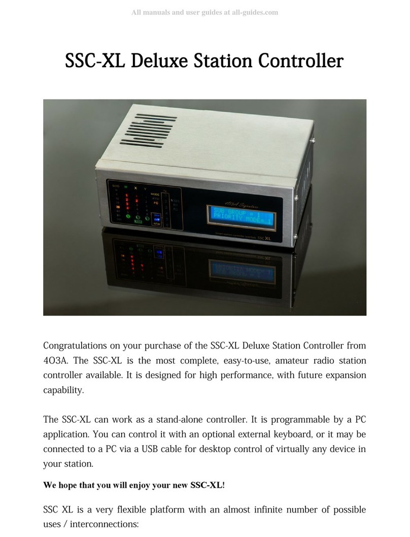
SSC-XL Deluxe Station Controller
Congratulations on your purchase of the SSC-XL Deluxe Station Controller from
4O3A. The SSC-XL is the most complete easy-to-use amateur radio station
controller available. It is designed for high performance with future expansion
capability.
The SSC-XL can work as a stand-alone controller. It is programmable by a PC
application. You can control it with an optional external keyboard or it may be
connected to a PC via a USB cable for desktop control of virtually any device in
your station.
We hope that you will enjoy your new SSC-XL!
SSC XL is a very flexible platform with an almost infinite number of possible
uses / interconnections:

Flexibility
Front panel overview
SSC-XL Front Panel
(1) BAND
Indicates current band in use.
(1) (2) (3) (4) (5)

(2)(3)(4) M X Y
These LED indicators are programmable freely in any way you desire. They
come in groups of 5. For example:
M–Main Antennas
X–ReceivingAntennas
Y–4Square or stack or whatever
The "S" LED indicates SPLIT operation and it lights up when there are multiple
antennas on one band.
(5) MODE LEDs
KYB/PC - These LEDs indicate whether Keyboard or PC control is engaged.
INT - Indicates that the Interlock mode is engaged.
INH - Indicates that the Inhibit function is engaged.
NTW – Marks the group of functions that require the network (INH INT).
PTT - This indicates that a PTT signal has been detected.
TX - One or more LEDs will light up if a transmitter in the network is active
showing you its corresponding number.
SO2R/R1/R2 - These LEDs will light up as appropriate during SO2R (Single
Operator
2 Radio) operation. R1 is Radio 1 and R2 is Radio 2.

Rear panel overview
(1) PTT Outputs (With Delay)- yellow RCA connector
Jumpers to program the PTT Outputs are located below it's RCA
connector socket. These outputs may include a programmable delay
for amplifier or preamplifier sequencing etc. The RCA jack can be
configured for either:
1. Closure to Ground (left position)
2. +12V DC on Transmit (right position)
The top position is for „normaly open“ configuration.
The bottom position is for „normaly closed“ configuration (shorted
on RX).
Delays can be programmed from the main configuration panel.
(2) PTT Outputs (No Delay) – white RCA connector
Jumpers to program the PTT Outputs are located below it's RCA
connector socket. These outputs have no delay compared to the PTT
Input.
The RCA jack can be configured for either:
1. Closure to Ground (left position) BIJELA!!
(2) (1)
(3)
(4)
(5)
(6)
(7)
( )
(9)
(10) (11) (12) (13) (14), (15) (16) (17)

2. +12V DC on Transmit (right position)
The top position is for „normaly open“ configuration.
The bottom position is for „normaly closed“ configuration (shorted
on RX).
(3) FS (Foot Switch) –black RCA connector
This RCA jack is a manual PTT input from a footswitch. This input always is
looking for a closure to ground on transmit.
Foot switch line is isolated with opto-coupler
(4) PTT In (Generic) ) – black RCA connector
This RCA jack accepts "PTT" input from any external device
such as a foot switch a relay or a line containing +5V or
+12V DC from a USB keying device or a PC interface.
PTT IN line is isolated with opto-coupler
BLACK!!
(5) Inhibit (Output) – red RCA connector
For blocking transmit capability of other transmitters if the
Inhibit Mode has been activated use this output RCA jack.
It's either +12V or GND. Jumpers to program this are
located below it's RCA connector socket.
(6) SWR Alarm– red RCA connector
This input RCA jack can accept a "High SWR" alarm (or any
other alarm state) from some external device (such as an
anatenna analyzer amplifier etc.) to block the transmitter
from putitng out any power. This input is expecting either
+5V DC or a closure to ground (programmable via a jumper
located below it's RCA connector socket).

SWR IN line is isolated with opto-coupler
(7) Band Data IN
This DIN connector accepts Band Data signals from a device capable of
generating the appropriate BCD data. The connector is directly compatible with
Yaesu Band Data jacks. Band data inpit lines are isolated with opto-coupler.
(8) Band Data OUT
This DIN connector feeds Band Data out for use with linear amplifiers or other
devices requiring the BCD data available on the Band Data control pins.
(9) AUX OUT
These DB9 female AUX sockets is used to connect the controller to the output
module unit. It uses a pin to pin cable.

Cable has to has GND on DB9 metal CASE!
(10) Interlock
When you desire to have units under control of the SSC-XL interlocked press
this button . The blue "INT" LED on the front panel will now be interlocked.
(11) Prio (Priority)
Should you desire to define a priority level within your station (for example to
allow the "Multiplier" station to seize control) use this button. Three different
Priority levels are available (1-3). Every time you click the button priority is
incremented. If the priority is 3 it will become 1 on the next click.
Initial statur is Priority 1!
(12) RJ-45
Use this jack to connect to a local switch/router in your station and allow the
SSC-XL to be a part of a local area network. TCP/IP is the main method of
communication between SSC-XL controllers. All operate in the 10.0.0.0/24
subnet.
RJ-45 connector has galvanic isolation from uC circuit.
(13) ADR (DIP Switch)
DIP switch is used for configuring devices when working together in a network.
Down position indicates ON (logical 1).
DIP 1-3 define the device number.
DIP 4-6 define the group number.
DIP 7 does nothing in the default firmware.
DIP 8 defines if the device is in server or client mode.

Make sure you don't duplicate device numbers in the same group. (If you do
only the first device you turn on will work.)
There can be 6 devices in a group and a maximum of 6 groups.
Below is the table with all possible configurations.
DEVICE ADDRESS GROUP ADDRESS Server/ Client
Device 1 1 0 0
Device 2 0 1 0
Device 3 1 1 0
Device 4 0 0 1
Device 5 1 0 1
Device 6 0 1 1
G oup 1 1 0 0
G oup 2 0 1 0
G oup 3 1 1 0
G oup 4 0 0 1
G oup 5 1 0 1
G oup 6 0 1 1
Client 0
Se ve 1
(14)/(15) RS232
These two DB-9 connectors may be used for CAT control or for any other
control purpose.
Three pins are used:
2 – RX
3 – TX
5 – GND
(16) DC 16V-18V

This 16V-18V DC connector is used to power the SSC-XL. Connect only to a DC
power source capable of 1000 mA of current. Polarity can be whatever!
Same connector can be supplied with 14V AC. SSC XL has power supply and
wrong polaritiy protection circuit built in.
(17) USB
This jack may be connected to the optional keypad. Selecting of the device type
is made by pressing the KYB/PC button appropriately.
USB connector is protected with dedicated protection IC.
(18) ANALOG Inputs (Not in use)
Additional hardware
Programming Keypad (optional)
The optional programming keypad
allows the SSC-XL to operate as a
stand-alone contoller without the
need for a personal computer.
The optional programming keypad
connects to the USB connector on
the rear panel of the SSC-XL.
You will get 4 colour stickers with
numbering from 1 to 5 to create
keayboard layount to fit your
personal needs.
Any standard ASCII keyboard should work but it is not guaranteed. Some
keyboards are recognized as hubs by Windows. These will not work.

OUTPUT MODULE UNIT
Relay output port Open collector GND port
( 2x8, GND,+12V or external)
Slika o tp t mod le nit-a - Slika izlaznih potrova i j mpera na mod l
One output module unit comes with every device. Each has 16 outputs. Devices
configured as „server“ can accept two more (three output module units total).

Each device directly controlls it's output module.
Server device can accept two more (three total) output units.
As with a client device the first module is controllable only from the master
device directly.
The two aditional units can be controlled via TCP/IP from any device on the
network.
Getting started
Setup and Interconnections
A typical interconnection diagrtam is shown below although there are almost
infinite possibilities as to interconnectins since the SSC-XL can control almost

anything in your station (including your coffee pot if you like).
Four devices in network connected to output modules
A DC adapter is supplied with your SSC-XL. We recommend you always use it
for powering the SSC-XL. We cannot guarantee full performance of the SSC-XL
when using a different power source.
Should you elect to use an external DC power supply it must provide 13.8 V DC
at a minimum current of 1000 mA. The DC power cable's center pin is the +V
line and the outer ring is the negative line. Be absolutely certain not to reverse
the DC supply voltage. Our limited warranty does not cover damage caused by
improper supply voltage or by reversed DC voltage or from the application of
AC voltage of any kind.

Setting up your first configuration
1. Connect the supplied DC power cable (from the power adapter) to the
rear panel of the SSC-XL.
2. Connect the SSC-XL to your PC with the USB cable.
.
SSC XL Configuration Panel
Download link:
http://4o3a.com/index.php/downloads
Follow the simple installation instructions there are no authentication
mechanisms.
This is an overview of 4O3A SSC XL Configuration Panel software. It is the main
documentation of its features. We will go over its features using a sample
configuration as an example
In case you accidently hide your window you can restore its visibility by double
clicking the application icon in the lower right corner of your screen
(sysTray).
This is an example of a Server configuration:

Example Server Config ration
You define groups of buttons for various switching. Multiple groups of buttons
can be active at the same time. You add groups of buttons by clicking the +
icon:
Add b tton gro p
Set the name of your button group by entering it in the text box. Orientation
Header Position and Panel size define the visual appearance of the group. You
can enable or disable your group at any time by using the Active checkbox .
Once disabled your group will disappear from screen:

Basic Settings
Sta t adding buttons by clicking the next + icon:
Adding b ttons
You can have different button layouts for different
bands. When connected (properly) to an SSC XL the
software will automatically recognize band changes
on your station. You can have completely different
button sets on each band. They can also overlap
(selecting multiple bands for a button group).
If no band is selected the button group will be
always visible regardless of the current band. See
chapter “Home automation” for more details.
While not connected to a station you can manually
change band by a menu right clicking the icon.
(for configuration purposes)
Band selection window
Start adding buttons by clicking the + Add icon:

Add b ttons
Active checkbox toggles if your button is currently enabled:
Active checkbox
Type the name of your button name into the button name text box:
B tton name
Click on the windows key box to set a globally available shortcut for using this
button:
Windows Key
Keyboard key is a single character from an external keyboard. It is a shortcut for
the button use when a USB keyboard is attached to the device. You have to
define it even if you do not intend to use an external USB keyboard:
Keyboard Key
Uncheck toggle if you want to deactivate all other buttons in the group when
using this one. If toggle is checked then this button can be used at the same
time with multiple other buttons from the group configured in the same way:
Toggle checkbox

You can set outputs by clicking the set desired outputs icon:
Set o tp ts
A menu will pop up where you can select desired outputs. You use one or
multiple relays per button on the connected board(s). You can select a single
LED from M X or Y group as an indication of pressed button. LEDs and relays
that are already in use in the configuration will be grayed out:
O tp t settings window
PTT checkbox has three possible states:
PTT legend
If unchecked there will be no output on PTT ports only the appropriate relay
will be turned on.
If checked there will be normal output on PTT ports as well as the appropriate
LED. You can also toggle between two different layouts one for receiving one
for transmitting. This allows use of different antenna layouts for receiving and
transmitting.
If checked with a black square it acts the same as regularly checked (PTT +
relay) but allows for only one layout on RX and TX:
PTT checkbox

You can delete buttons by clicking delete:
Delete b tton
If you set split signal your antenna splitter will activate impedance transformer
automatically every time multiple antennas are active:
Set split signal
Alternatively you can use Configuration -> Split Signals
Choose the relay to what your splitter is connected. The S LED on the device will
indicate that split signal is active. Up to three possible splitters per group (M X
Y)
Split signal window

Below is the schematic of the power splitter with the Split signal relay marked.
Split signal will activate relays marked with yellow:
Power splitter schematic
CONFIGURATON MENU
From the configuration menu you can create new configurations save existing
on the hard drive or upload a configuration to the controller. You can also
configure your device IP address COM port settings define split signals and
create band reports (output is pure text files):
Config ration drop down men
Set up your IP / COM protocol parameters in

You can select your radio by name if
supported in the current version and the
COM parameters will be automatically set.
More models will be added with every new
version so make sure you update.
If you know COM settings some unsupported
devices might but do not necessarily have to
work because the protocols below seem to
vary.
Please contact us for any specific requests via
email: [email protected]
COM port settings
Note that Automatic IP does not mean you can
use DHCP to assign addresses.
Automatic IP means that the address will be
defined based on DIP switches on the back
and that means it will be in the 10.0.0.0/8 IP
range.
You can specify custom addresses if you like.
In case of server the IP Address and Server
IP have to be the same.
If you are setting a client you have to enter
the correct server IP for each client device.
COM port settings
Other manuals for SSC-XL
1
Table of contents
Other 4O3A Controllers manuals
Popular Controllers manuals by other brands

Viking Electronics
Viking Electronics SLP-1 Installation and application manual

Berker
Berker 8526 51 00 Operation instructions

Zmotion
Zmotion ZMC464 Hardware manual

Azbil
Azbil Infilex VC Specifications & instructions

WAVESTREAM
WAVESTREAM RMC-RRS011-HE01 Operation manual

Infineon
Infineon XDPP1100 Technical reference manual