manuals.online logo
Brands
  1. Home
  2. •
  3. Brands
  4. •
  5. AMX
  6. •
  7. Matrix Switcher
  8. •
  9. AMX Precis LT User manual

AMX Precis LT User manual

Quick Start Guide
AutoPatch PrecisLT Distribution Matrix
Overview
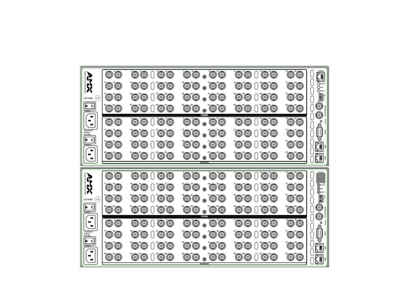
The PrecisLT Distribution Matrix is available in various sizes and board configurations;
therefore the illustrations in this guide may differ from the model(s) you purchased.
The PrecisLT is available in the following models:
Configurations available: 4x4, 4x8, 8x4, and 8x8. The PrecisLT Instruction Manual
contains complete documentationfor this product; see the AMX AutoPatch Software &
Documentation CD or visit www.amx.com.
General Specifications
Installation
ESD Warning: Avoid ESD (Electrostatic Discharge) damage to
sensitive components; be sure you and the enclosure(s) are
properly grounded before touching any internal materials.
Rack Mounting
To rack mount a PrecisLT enclosure:
1. Attach the rack ears as shown in FIG. 1 (screws provided).
2. Install in a rack (we recommend leaving a minimum of one empty rack unit
above and below).
Attaching Input & Output Cables/Wires
Attach sources and destinations to the PrecisLT according to the labels on the
enclosure.
Standard & Component Video – BNC
Video BNC connectors are used for standard and component video. Component
signals (e.g., Y/Pb/Pr) require more than one BNC connection. The example in FIG. 2
shows three BNC cable connectors attached for routing a three-component signal as
Input 1.
S-Video
AutoPatch S-Video cables lock on to S-Video connectors. Standard S-Video cables
may be used, but will not lock.
To fasten a locking S-Video connector: hold the connector at a slight angle to
the right while pushing in or pull back on the connector housing while pushing the
connector in.
RGBHV/HD-15
RGBHV/HD-15 connectors use the pinouts in FIG. 4.
Note: 55 mA supplied on output pin 9; power draw not to exceed 50 mA per port.
Stereo Audio – 3-Term (RGBHV/HD-15 Model Only)
Three-position terminal block connectors are wired for unbalanced (single-ended)
stereo audio (see FIG. 5).
More than one of the options shown in FIG. 6 can be used in the same system.
• Standard Video & Stereo • Component Video & Stereo
• S-Video & Stereo • RGBHV/HD-15 & Stereo
Specifications
Approvals CE, UL, cUL
AC Power 100 - 240 VAC single phase (50 - 60 Hz)
Power Consumption per enclosure:
Standard Video & Stereo
S-Video & Stereo
Component Video & Stereo
RGBHV/HD-15 & Stereo
35 Watts (max.), 15 Watts (typical)
60 Watts (max.), 25 Watts (typical)
Operational Temperature 32° - 110° F (0° - 43° C)
Humidity 0 to 90% non-condensing
Dimensions (depth & width) 10.4 in. (26.42 cm) depth
19.0 in. (48.26 cm) width with mounting ears
17.4 in. (44.20 cm) width without mounting ears
Height 1 RU Models: 1.7 in. (4.32 cm)
2 RU Models: 3.5 in. (8.89 cm)
Weight per enclosure 1 RU Models: Approx. 7.0 lb. (3.18 kg)
2 RU Models: Approx. 10.5 lb. (4.75 kg)
FIG. 1 Attach 2 RU rack ears Attach 1 RU rack ears
FIG. 2 Three BNC connectors are required for a three-component signal
FIG. 3 Pull back on connector housing while pushing in
FIG. 4 HD-15 input and output board connector pinouts
FIG. 5 Insert the wires and re-tighten clamps
FIG. 6 Options for source-to-PrecisLT-to-destination 3-Term wiring
Connector housing
For full warranty information, refer to the AMX AutoPatch Instruction Manual(s) associated with your Product(s).
3/07
©2007 AMX. All rights reserved. AMX and the AMX logo are registered trademarks of AMX.
AMX reserves the right to alter specifications without notice at any time.
3000 RESEARCH DRIVE, RICHARDSON, TX 75082 • 800.222.0193 • fax 469.624.7153 • technical support 800.932.6993 • www.amx.com
93-37-861 REV: A0
Stereo Audio – 5-Term
Five-position terminal block connectors can be wired for balanced (differential) or
unbalanced (single-ended) stereo audio.
Note: When using a shielded twisted-pair cable, connect the shield (ground) at one
end only (recommend receiving end) to minimize low frequency noise (see FIG. 8).
Source and destination devices require either balanced or unbalanced connections.
More than one of the options shown in FIG. 8 can be used in the same system.
Video & Audio – RCA
RCA connectors are used for component video and unbalanced stereo audio.
The example in FIG. 9 shows RCA jacks attached for routing Y/Pb/Pr and stereo
audio source signals as Input 1.
Establishing Serial Control (if applicable)
The PrecisLT can be controlled by attaching an external control device/system to the
RS-232 serial port.
Serial Control (PCs & third-party controllers)
Use the pinout in FIG. 10 when connecting a PC to the PrecisLT serial port.
To establish external serial control:
1. Plug the null modem cable into the serial port on the enclosure
(see FIG. 11 top of next column).
2. Plug the other end of cable into the serial port on the serial controller/device.
3. Open serial communication software and set port settings to match the
PrecisLT settings (baud = 9600, data bits = 8, stop bit = 1, parity and flow
control = none).
Applying Power & Control Startup
Important: We recommend attaching all power cords to a surge protector and/or
an AC line conditioner.
To apply power:
1. Attach power cord(s) and plug into power source (turn on power source if
necessary). Press the “l” side of the enclosure’s power switch. The Power
Indicator on the front of the enclosure illuminates.
2. Apply power to any external devices (PCs, SBCs, etc.) and then to the source
and destination devices.
Completing the Installation
We recommend completing the installation by executing a test switch routing Input 1
to Output 2. The PrecisLT ships with a default switch routing Input 1 to all outputs.
This default switch must be disconnected before performing a test switch. The
method of executing the switch depends on the control option used (see below).
•Front Control Panel – press Cancel Key to ensure panel is in Switch Mode.
To disconnect the default switch: Press Input Key 1. Input Key 1 blinks and all
output keys illuminate. Press each output key, then press the Take Key. When
all the output keys turn off, the default switch is disconnected.
To execute a test switch: Press Input Key 1. Input Key 1 blinks. Press Output
Key 2. Output Key 2 illuminates. Press the Take Key. When the illuminated
keys turn off, the switch is successful.
•NetLinx® or Duet Compatible Devices – see the specific controller device
documentation for instructions on installation and executing switches.
•APControl 3.0 (PC based) – install and open the program. From the
APControl Launchbar menu, select System/New; select Heritage System/Next;
select Manual Configuration Entry/Next; enter and Add VM information/Next;
finish Wizard instructions. From the Launchbar menu, select Views/CrossBar
and click on the crosspoint for Input 1 / Output 2.
•APWeb – connect the APWeb Module (see the APWeb Module Quick Start
Guide). For instructions on executing switches, see the APWeb (Interface)
supplement on the AMX AutoPatch CD.
•BCS Commands (HyperTerminal) – when power is applied, a short splash
screen appears.
To disconnect the default switch: enter DI1T into the terminal
emulation program.
To execute a test switch: Enter CI1O2T (routes Input 1 to Output 2). When
CI1O2T appears, the switch is successful.
The system is now ready to attach the remaining source and destination devices.
Additional Information Covered in PrecisLT Instruction Manual
See the instruction manual on the CD or at www.amx.com for the following:
• Control panel operations
• BCS commands for system operation
• Product specifications for specific models
FIG. 7 Balanced audio Unbalanced audio
FIG. 8 Options for source-to-PrecisLT-to-destination 5-Term wiring
FIG. 9 Insert the RCA plugs into the RCA jacks
FIG. 10 RS-232 null modem cable pin diagram
FIG. 11 Connect the null modem cable to the serial port
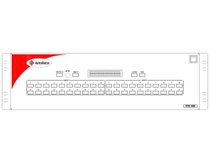
FIG. 12 Typical PrecisLT control panel
Serial port
Null modem
serial cable
Take Key
Level Keys Input Keys
Command Keys Output Keys
Power Indicator
Other manuals for Precis LT

4

This manual suits for next models

1

Other AMX Matrix Switcher manuals

AMX Optima User manual

AMX

AMX Optima User manual

AMX AVS-OCT-4832-117 Instructions and recipes

AMX

AMX AVS-OCT-4832-117 Instructions and recipes

AMX AVS-OP-2404-540 User manual

AMX

AMX AVS-OP-2404-540 User manual

AMX AVS-OP-2020-540 Instructions and recipes

AMX

AMX AVS-OP-2020-540 Instructions and recipes

AMX DUX-12F User manual

AMX

AMX DUX-12F User manual

AMX AVS-OCT-4864-217 Instructions and recipes

AMX

AMX AVS-OCT-4864-217 Instructions and recipes

AMX Precis DSP User manual

AMX

AMX Precis DSP User manual

AMX AVS-OP-2416-347 User manual

AMX

AMX AVS-OP-2416-347 User manual

AMX Epica DGX 288 User manual

AMX

AMX Epica DGX 288 User manual

AMX AVS-OP-1624-540 Instructions and recipes

AMX

AMX AVS-OP-1624-540 Instructions and recipes

AMX AVS-OCT-4864-560 Instructions and recipes

AMX

AMX AVS-OCT-4864-560 Instructions and recipes

AMX Epica DG User manual

AMX

AMX Epica DG User manual

AMX AVS-OCT-6448-217 Instructions and recipes

AMX

AMX AVS-OCT-6448-217 Instructions and recipes

AMX AVS-OP-2404-217 User manual

AMX

AMX AVS-OP-2404-217 User manual

AMX AVS-OCT-6464-117 Instructions and recipes

AMX

AMX AVS-OCT-6464-117 Instructions and recipes

AMX AVS-OP-3604-540 User manual

AMX

AMX AVS-OP-3604-540 User manual

AMX AVS-OP-3604-340 User manual

AMX

AMX AVS-OP-3604-340 User manual

AMX AVS-OCT-4864-567 Instructions and recipes

AMX

AMX AVS-OCT-4864-567 Instructions and recipes

AMX Distribution Matrix Octaire User manual

AMX

AMX Distribution Matrix Octaire User manual

AMX AVS-OP-1624-340 Instructions and recipes

AMX

AMX AVS-OP-1624-340 Instructions and recipes

AMX AVS-OP-2404-340 User manual

AMX

AMX AVS-OP-2404-340 User manual

AMX AVS-OP-2004-547 Instructions and recipes

AMX

AMX AVS-OP-2004-547 Instructions and recipes

AMX Octaire Distribution Matrix AutoPatch User manual

AMX

AMX Octaire Distribution Matrix AutoPatch User manual

AMX AVS-OP-1616-340 Instructions and recipes

AMX

AMX AVS-OP-1616-340 Instructions and recipes

Popular Matrix Switcher manuals by other brands

CYP CMSI-8H8HC Operation manual

CYP

CYP CMSI-8H8HC Operation manual

CYP PU-8H8HBTPL Operation manual

CYP

CYP PU-8H8HBTPL Operation manual

Kramer VS-88SDI user manual

Kramer

Kramer VS-88SDI user manual

Kramer VP-4x4K user manual

Kramer

Kramer VP-4x4K user manual

Key Digital Digital IQ Series Setup guide

Key Digital

Key Digital Digital IQ Series Setup guide

Matrix Switch Corporation MSC-HD121DEL product manual

Matrix Switch Corporation

Matrix Switch Corporation MSC-HD121DEL product manual

GONSIN GX-SDI0808 user manual

GONSIN

GONSIN GX-SDI0808 user manual

Putron Electronics RGBHV user manual

Putron Electronics

Putron Electronics RGBHV user manual

Kramer VS-2616 user manual

Kramer

Kramer VS-2616 user manual

ATEN VM0202H user manual

ATEN

ATEN VM0202H user manual

Bewator Visilynx 3 Series user manual

Bewator

Bewator Visilynx 3 Series user manual

Lindy 38051 user manual

Lindy

Lindy 38051 user manual

Gefen EXT-HDFST-848CPN user manual

Gefen

Gefen EXT-HDFST-848CPN user manual

Intelix DIGI-HD-4X4 manual

Intelix

Intelix DIGI-HD-4X4 manual

Kramer VP-729 user manual

Kramer

Kramer VP-729 user manual

Kramer VS-88H2A quick start guide

Kramer

Kramer VS-88H2A quick start guide

Ecler MIMO4040CDN user manual

Ecler

Ecler MIMO4040CDN user manual

WolfPack HDTVHDMX0808 user manual

WolfPack

WolfPack HDTVHDMX0808 user manual

manuals.online logo
manuals.online logoBrands
  • About & Mission
  • Contact us
  • Privacy Policy
  • Terms and Conditions

Copyright 2025 Manuals.Online. All Rights Reserved.