910 East Orangefair Ln. Anaheim, CA 92801 Tel. (714) 992-6990 Fax. (714) 992-0471 www.anaheimautomation.com
Step 6:
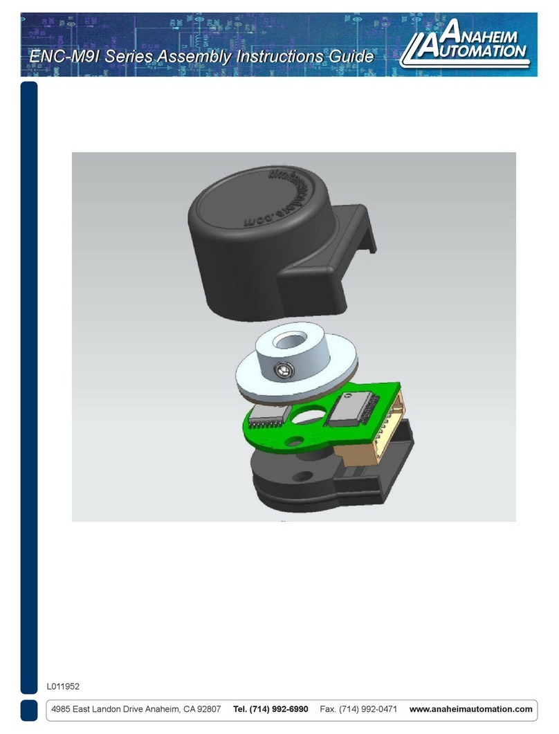
After the encoder is properly timed, place the included
tool over the encoder. Be careful to avoid rotating the
encoder. This tool will push the external ring all the
way to the base of the encoder which will lock it in its
nal position. Remove tool when this is complete.
Step 7: (Optional)
Apply the center hole cover seal over the opening on
top of the encoder.
Step 5: Dynamic Timing of Encoder
This step requires two motors. The second motor will
back drive the target motor. First, connect motor U
winding and encoder U output to two separate
channels on an oscilloscope. With the motor running
and output being displayed on the oscilloscope, rotate
the encoder until the two signals are aligned with each
other as seen on the gure on the right.
The encoder allows full 360° of rotation to allow for
complete synchronization of the U winding with the U
encoder output.
