AD9776A/AD9778A/AD9779A
Rev. A | Page 2 of 60
TABLE OF CONTENTS
Features .............................................................................................. 1
Applications....................................................................................... 1
General Description......................................................................... 1
Product Highlights ........................................................................... 1
Typical Signal Chain......................................................................... 1
Revision History ............................................................................... 2
Functional Block Diagram .............................................................. 3
Specifications..................................................................................... 4
DC Specifications ......................................................................... 4
Digital Specifications ................................................................... 5
Digital Input Data Timing Specifications ................................. 6
AC Specifications.......................................................................... 6
Absolute Maximum Ratings............................................................ 7
Thermal Resistance ...................................................................... 7
ESD Caution.................................................................................. 7
Pin Configurations and Function Descriptions ........................... 8
Typical Performance Characteristics ........................................... 14
Terminology .................................................................................... 22
Theory of Operation ...................................................................... 23
Differences Between AD9776/AD9778/ AD9779 and
AD9776A/AD9778A/AD9779A............................................... 23
Serial Peripheral Interface ............................................................. 24
General Operation of the Serial Interface ............................... 24
Instruction Byte .......................................................................... 24
Serial Interface Port Pin Descriptions ..................................... 25
MSB/LSB Transfers..................................................................... 25
SPI Register Map............................................................................. 26
Interpolation Filter Architecture .................................................. 31
Interpolation Filter Bandwidth Limits .................................... 35
Sourcing the DAC Sample Clock ................................................. 36
Direct Clocking .......................................................................... 36
Clock Multiplication .................................................................. 36
Driving the REFCLK Input....................................................... 38
Full-Scale Current Generation ..................................................... 39
Internal Reference ...................................................................... 39
Transmit Path Gain and Offset Correction................................. 40
I/Q Channel Gain Matching..................................................... 40
Auxiliary DAC Operation......................................................... 40
LO Feedthrough Compensation .............................................. 41
Results of Gain and Offset Correction .................................... 41
Input Data Ports ............................................................................. 42
Single Port Mode ........................................................................ 42
Dual Port Mode .......................................................................... 42
Input Data Referenced to DATACLK...................................... 42
Input Data Referenced to REFCLK ......................................... 43
Optimizing the Data Input Timing.......................................... 44
Device Synchronization................................................................. 45
Synchronization Logic Overview............................................. 45
Synchronizing Devices to a System Clock .............................. 46
Interrupt Request Operation .................................................... 46
Power Dissipation........................................................................... 47
Power-Down and Sleep Modes................................................. 48
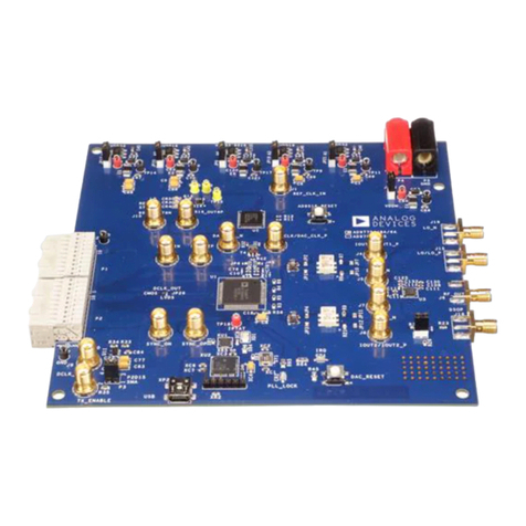
Evaluation Board Operation......................................................... 49
Using the ADL5372 Quadrature Modulator .......................... 51
Evaluation Board Schematics ................................................... 52
Outline Dimensions....................................................................... 60
Ordering Guide .......................................................................... 60
REVISION HISTORY
3/08—Rev. 0 to Rev. A
Changes to Features.......................................................................... 1
Added Note 2 .................................................................................... 4
Changes to Table 2............................................................................ 5
Changes to Table 3............................................................................ 6
Changes to Thermal Resistance Section........................................ 7
Inserted Table 6................................................................................. 8
Changes to Pin 39 Description, Table 7......................................... 9
Changes to Pin 39 Description, Table 8....................................... 10
Changes to Pin 39 Description, Table 9....................................... 12
Changes to Theory of Operation Section.................................... 23
Changes to Table 10 ....................................................................... 23
Changes to Table 13 ....................................................................... 26
Changes to Table 14 ....................................................................... 27
Changes to Interpolation Filter Architecture Section ............... 33
Replaced Sourcing the DAC Sample Clock Section .................. 36
Replaced Transmit Path Gain and Offset Correction Section . 40
Replaced Input Data Ports Section .............................................. 42
Replaced Device Synchronization Section.................................. 45
Deleted Figure 112 to Figure 117 ................................................. 58
8/07—Revision 0: Initial Version
Downloaded from Elcodis.com electronic components distributor
