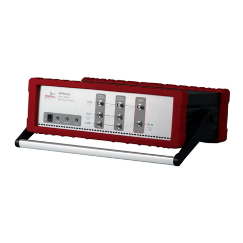
AnaPico APPH6040 User manual

Anapico AG Europastr. 9 CH-8152 Glattbrugg Switzerland Tel: +41 44 515 5501 www..anapico.com
1
User’s Manual 2.2 (March 2014)
APPH Models
APPH6040, APPH20G, APPH6000
-IS400

Anapico AG Europastr. 9 CH-8152 Glattbrugg Switzerland Tel: +41 44 515 5501 www..anapico.com
2
WARRANTY
All Anapico instruments are warranted against defects in material and workmanship for a period of two years
from the date of shipment. Anapico will, at its option, repair or replace products that prove to be defective during
the warranty period, provided they are returned to Anapico and provided the preventative maintenance
procedures are followed. Repairs necessitated by misuse of the product are not covered by this warranty. No
other warranties are expressed or implied, including but not limited to implied warranties of merchantability and
fitness for a particular purpose. Anapico is not liable for consequential damages.
IMPORTANT! PLEASE READ CAREFULLY
Copyright
This manual is copyright by Anapico AG and all rights are reserved. No portion of this document may be
reproduced, copied, transmitted, transcribed stored is a retrieval system, or translated in any form or by
any means. Electronic, mechanical, magnetic, optical, chemical, manual or otherwise, without written
permission of Anapico AG.

Anapico AG Europastr. 9 CH-8152 Glattbrugg Switzerland Tel: +41 44 515 5501 www..anapico.com
3
Table of Contents
TABLE OF CONTENTS................................................................................................................................ 3
1INTRODUCTION TO THE APPH ................................................................................................................. 5
1.1 GENERAL FEATURES AND FUNCTIONS ................................................................................................................ 5
1.2 OPTIONS...................................................................................................................................................... 5
1.3 FRONT PANEL OVERVIEW ................................................................................................................................ 6
1.4 REAR PANEL CONNECTIONS ............................................................................................................................. 8
2GETTING STARTED................................................................................................................................. 10
2.1 SYSTEM REQUIREMENTS................................................................................................................................ 10
2.2 UNPACKING THE APPH ................................................................................................................................ 10
2.3 INITIAL INSPECTION ...................................................................................................................................... 10
2.4 STARTING THE APPH ................................................................................................................................... 10
2.4.1 Applying Power ............................................................................................................................. 10
2.4.2 Connecting to LAN via DHCP Router.............................................................................................. 10
2.4.3 Connecting via LAN without DHCP Router (fallback or fixed IP).................................................... 11
2.4.4 Connecting through USB to APPH GUI .......................................................................................... 11
2.4.5 Connecting through USBTMC & VISA ............................................................................................ 11
2.4.6 Connecting through GPIB & VISA .................................................................................................. 12
2.4.7 Using Anapico Application Programming Interface (API).............................................................. 12
2.4.8 Installing the APPH Graphical User Interface Software................................................................. 12
2.4.9 Troubleshooting ............................................................................................................................ 12
2.4.10 Shutting Down the APPH .......................................................................................................... 13
2.4.11 Perform Firmware Upgrade...................................................................................................... 13
2.4.12 Serial Number ........................................................................................................................... 13
3MEASUREMENT USING THE GRAPHICAL USER INTERFACE (GUI) ........................................................... 14
3.1 START THE APPH GUI.................................................................................................................................. 14
3.2 ORGANIZATION OF THE GUI .......................................................................................................................... 15
3.2.1 Menu Section................................................................................................................................. 15
3.3 MEASUREMENT TABS ................................................................................................................................... 21
3.3.1 General Tab Organization ............................................................................................................. 21
3.4 PHASE NOISE MEASUREMENT TAB.................................................................................................................. 22
3.4.1 Measurement setup ...................................................................................................................... 22
3.4.2 Using External References ............................................................................................................. 26
3.4.3 The Different Plot Window Tabs.................................................................................................... 27
3.4.4 The Traces Window ....................................................................................................................... 29
3.4.5 The Marker Window...................................................................................................................... 32
3.4.6 Inside Plot Window Functions ....................................................................................................... 33
3.4.7 Saving Traces................................................................................................................................. 34
3.4.8 Oversampling factor (APPH6000 / APPH30G only) ....................................................................... 34
3.5 GENERAL MEASUREMENT SETTINGS ................................................................................................................ 36
3.5.1 Number of data points per trace ................................................................................................... 36
3.5.2 Measurement time (using GUI) ..................................................................................................... 36
3.6 AM NOISE MEASUREMENT (APPH6000 ONLY) ............................................................................................... 38
3.7 ADDITIVE PHASE NOISE MEASUREMENT........................................................................................................... 39
3.7.1 Measurement Procedure............................................................................................................... 39
3.8 TRANSIENT ANALYZER MEASUREMENT ............................................................................................................ 43
3.9 FFT ANALYZER MEASUREMENT...................................................................................................................... 44
4SYSTEM CALIBRATION (FIRMWARE 1.0 AND UP)................................................................................... 45
5REMOTE PROGRAMMING THE APPH..................................................................................................... 47

Anapico AG Europastr. 9 CH-8152 Glattbrugg Switzerland Tel: +41 44 515 5501 www..anapico.com
4
5.1 ACCESS VIA LAN.......................................................................................................................................... 47
5.2 USING AND CONFIGURING VXI-11.................................................................................................................. 47
5.3 USING THE USB-TMC INTERFACE WITH VISA................................................................................................... 48
5.4 USING THE USB-TMC INTERFACE WITH IVI DRIVERS.......................................................................................... 48
5.5 USING THE GPIB INTERFACE .......................................................................................................................... 48
6TYPE AND STRUCTURE OF COMMANDS ................................................................................................ 49
6.1 APPH COMMANDS ...................................................................................................................................... 49
6.1.1 IEEE common commands .............................................................................................................. 49
6.1.2 Using SCPI for APPH ...................................................................................................................... 49
7MAINTENANCE AND WARRANTY INFORMATION.................................................................................. 50
7.1 ADJUSTMENTS AND CALIBRATION ................................................................................................................... 50
7.2 REPAIR ...................................................................................................................................................... 50
7.3 UPGRADING THE FIRMWARE VIA LAN.............................................................................................................. 50
7.4 SAFETY ...................................................................................................................................................... 50
7.5 WARRANTY INFORMATION ............................................................................................................................ 51
7.6 EQUIPMENT RETURNS .................................................................................................................................. 51

Anapico AG Europastr. 9 CH-8152 Glattbrugg Switzerland Tel: +41 44 515 5501 www..anapico.com
5
1 Introduction to the APPH
Your APPH kit contains the following items:
APPH mainframe
Universal power adaptor (AC 100 –240V)
Ethernet Cable
APPH software CD
It is strongly recommended to use the original power adaptor (as supplied with the device) to
guarantee save and reliable operation of the APPH.
1.1 General Features and Functions
The different APPH models offer different measurement capabilities as shown in the table below:
Model
APPH6000-IS400
APPH6040
APPH20G
RF frequency
5 MHz to 400
5 MHz to 7 GHz
5 MHz to 26 GHz
Offset range
0.1 Hz to 1 MHz
0.1 Hz to 50 MHz
0.1 Hz to 50 MHz
Absolute Phase Noise Mode
Y
Y
Y
Additive Phase Noise Mode
Y
Y
Y
Amplitude Noise Mode
Y
N
N
FFT Analyzer Mode
Y
Y
Y
Transient Measurement Mode
N
Y
Y
Features of all models include
Long-term support: software upgrades (firmware and PC based) are available to download
from www.anapico.com. You can also call our technical specialists for support. You can
continue to use both of these services free of charge for the lifetime of the product.
Universal LAN and USB 2.0 interface
24 months calibration cycle
1.2 Options
The following options are available for the APPH signal analyzer:
GPIB GPIB interface added
SUPPLY Dual programmable low noise supply
LN Ultra Low close to carrier phase noise internal references

Anapico AG Europastr. 9 CH-8152 Glattbrugg Switzerland Tel: +41 44 515 5501 www..anapico.com
6
1.3 Front Panel Overview
Depending on the APPH product configuration, the front panel can contain up to five female SMA
connectors and two female BNC connectors. A green LED indicates the power on/off status of the
instrument.
Figure 1 Front Panel Views of APPH6000-IS400 and APPH20G
DUT/RF IN connector This female SMA connector is the DUT signal input. The input is AC-coupled
and the impedance is 50 ohm. The damage level is +26 dBm maximum. The maximum allowed DC
level is +/- 10 V.
Channel 1 and 2:
REF IN connector This female SMA connector is the reference LO input. The impedance is
50 ohm. The damage level is +20 dBm. The maximum allowed DC level is +/- 10 V.
REF OUT connector (APPH6000 ONLY) This female SMA connector is the reference LO
output. The impedance is 50 ohm. In standard operation with internal references the REF
OUT is connected by a short semi-rigid cable to the REF IN.

Anapico AG Europastr. 9 CH-8152 Glattbrugg Switzerland Tel: +41 44 515 5501 www..anapico.com
7
TUNE connector This female BNC connector is the DC tune voltage output if a tuneable DUT
or tuneable external reference is used.
Power switch The power switch disconnects the instrument from the DC input completely.
Caution:
Do not apply a DC voltage or current to the individual ports of the DC Control, DC Power and
RF Port. Applying a DC voltage or current may lead to the breakdown of this product. In
particular, there is the risk of the capacitor remaining charged. Connect the measurement
sample (DUT) to the port (or the test fixture, cables, etc. connected to the port) after
discharging DUT's electricity enough.

Anapico AG Europastr. 9 CH-8152 Glattbrugg Switzerland Tel: +41 44 515 5501 www..anapico.com
8
1.4 Rear Panel Connections
In Figure 2 the rear panels is shown for different APPH models.
Figure 2 Rear Panel Views of APPH6000-IS400 and APPH20G
Channel 1 and 2:
SUPPLY connector This female BNC connector is the programmable low-noise DC supply
voltage output. APPH6000: Output voltage range is 0 V to +5 V, maximum available current is
80 mA. APPH6040/20G: Output voltage range is 0 V to +15 V, maximum available current is
500 mA.
BASEBAND IN connector This female BNC connector is the baseband signal input. To make
baseband noise measurement mode useful for power supply noise measurement, this port is
well protected for DC voltage application. The maximum allowed DC level is +/- 15 V.

Anapico AG Europastr. 9 CH-8152 Glattbrugg Switzerland Tel: +41 44 515 5501 www..anapico.com
9
LAN connector (8 Pin) This RJ-45 Host connector is used for connecting via Ethernet with a
controller, such as a PC or Laptop. 10Base-T/100Base-T Ethernet (automatic data rate
selection).
USB B connector Used for connecting with a controller such as a PC or Laptop.
Communication is via USBTMC protocol. Through this port, you can control the APPH from
external controllers. For more information on the measurement system using the USB port,
see the programmer’s manual.
USB A connector Used for connecting USB devices such as Memory sticks.
DC IN power receptacle The power receptacle accepts a two-pin plug from the external 6 or
24 V DC power adapter.
GPIB (optional) connector The connection of an external controller through General Purpose
Interface Bus (GPIB) connector allows you to configure an automatic measurement system.
This GPIB connector is used only for controlling the APPH-IS from an external controller. You
cannot control other devices from the APPH through this GPIB connector.
Serial Number Plate The seal showing the serial number of the product.

Anapico AG Europastr. 9 CH-8152 Glattbrugg Switzerland Tel: +41 44 515 5501 www..anapico.com
10
2 Getting Started
2.1 System Requirements
To ensure that your APPH signal analyzer operates correctly with the remote control interface
software, you must have a computer with at least the minimum system requirements to run one of the
supported operating systems.
Operating system Windows™ (2000 SP4, XP SP2, 7, 8)
Minimum 1024 MB RAM
Ethernet Port 10/100/1000M LAN or USB 2.0 Port
2.2 Unpacking the APPH
Remove the APPH materials from the shipping containers. Save the containers for future use.
2.3 Initial Inspection
Inspect the shipping container(s) for damage. If container is damaged, retain it until contents of the
shipment have been verified against the packing list and instruments have been inspected for
mechanical and electrical operation.
2.4 Starting the APPH
The following sections describe installation instructions and APPH verification tests.
2.4.1 Applying Power
1. Place the APPH on the intended workbench and connect the appropriate DC power supply to
the receptacle on the rear of the unit. Make sure you use the included DC power supply. The
APPH requires 6 V DC at 6 A maximum. Using other supplies may lead to malfunction
and damage of the APPH.
2. Press the Line on/off switch on the front panel. The green front panel LED will illuminate. The
instrument will initialize and boot within about 45 seconds and be ready for operation.
2.4.2 Connecting to LAN via DHCP Router
Connect the APPH to your local area network (LAN) using the provided Ethernet cable. The
instrument is configured to accept its dynamic IP number from the DHCP server of your network. If

Anapico AG Europastr. 9 CH-8152 Glattbrugg Switzerland Tel: +41 44 515 5501 www..anapico.com
11
configured properly, your network router will assign a dynamic IP number to the instrument. Your
instrument is now ready to be controlled.
2.4.3 Connecting via LAN without DHCP Router (fallback or fixed IP)
You can connect the instrument to your computer with the Ethernet cable without using a local area
network with DHCP server. To work properly, the network controller (NIC) of your computer must be
set to a fixed IP beginning with 169.254.xxx.xxx (excluding 169.254.1.0 and 169.254.254.255) and
network mask 255.255.0.0 to match the fallback IP that the APPH will assign itself after network
timeout. The APPH will automatically choose an IP address according to ZEROCONF standard.
Therefore, the exact fallback address can’t be predicted.
Connection from a NIC that is configured to use DHCP is also possible. After a preset timeout, the NIC
will assume that no DHCP is available and self-assign a fallback IP that will fall into the range
169.254.xxx.xxx.
Alternatively, you may assign the instrument a fixed IP. Please refer to a later section of this manual to
learn how to do this.
2.4.4 Connecting through USB to APPH GUI
The APPH can also be controlled under Windows with standard USBTMC drivers.
Connect the APPH (USB B port) to the PC using a standard USB cable. The USB (IVI drivers) drivers
are installed along with the GUI installation process that can be started from the provided installation
CD or can be downloaded from the Anapico website.
If installed properly, the Windows operating system will automatically detect the APPH as a USBTMC
device and the APPH GUI will list it in its connection dialog.
2.4.5 Connecting through USBTMC & VISA
Connect the APPH (USB B port) to the PC using a standard USB cable. Once connected properly, use
VISA Write to send the *IDN? query and use VISA Read to get the response. The USBTMC protocol
supports service request, triggers and other GPIB specific operations.
VISA now allows you to communicate as a controller to the APPH. To use such device, plug it in and
Windows should detect the new hardware and launch the New Hardware Wizard. Instruct the wizard
to search for the driver, which in this case is VISA. If the VISA runtime library is properly installed, the
device will be installed as a USB Test & Measurement Class Device. Open Measurement &
Automation Explorer (MAX). The new device will appear in MAX under Device and Interfaces » USB
Devices. You can then use this resource name as you would use any GPIB resource.

Anapico AG Europastr. 9 CH-8152 Glattbrugg Switzerland Tel: +41 44 515 5501 www..anapico.com
12
2.4.6 Connecting through GPIB & VISA
Connect the APPH to the rear GPIB connector (option GPIB). Once connected properly, use VISA
Write to send the *IDN? query and use VISA Read to get the response. The protocol supports service
request, triggers and other GPIB specific operations.
VISA now allows you to communicate as a controller to the APPH.
2.4.7 Using Anapico Application Programming Interface (API)
Please refer to the APPH Programmer’s Manual to learn more about applying the API and
programming examples.
2.4.8 Installing the APPH Graphical User Interface Software
Anapico’s graphical user interface provides an intuitive control of the APPH. The Java based
application runs under any Operating System including Windows™ 2000, XP, Vista, 7, or 8 with
standard requirements. Only the Java runtime environment must be installed on the PC.
To install the GUI on the computer, insert the APPH Software and Manual CD into the CD/DVD drive
or download the latest GUI setup file from the Anapico website. If the setup doesn’t start automatically
double click on the setup.exe to run the auto-installer.
The self-extracting setup provides easy installation and de-installation of the software. The setup
program guides you in a few steps though the installation process. In case the Java Runtime
Environment is not installed on your current computer, the setup procedure automatically will assist
you with the installation of the required version. For this you will need an internet connection.
2.4.9 Troubleshooting
Software does not install or start properly
Make sure your installation CD is not damaged.
Verify that the Java Runtime Environment is installed and up to date
Software cannot detect any APPH
Make sure you have connected both PC and APPH to a common network. If they are not in
the same subnet, the search won't show the APPH, but you can still connect by manually
setting the IP in the connection dialog.
If connecting with USB, make sure that the IVI drivers have been installed during GUI
installation (default). The drivers can be reinstalled using the GUI setup procedure.
Note that detection of the APPH can take several seconds if your PC is configured to work
with an external DHCP server but the DHCP is not available. In some cases the connection
may even fail completely. Check your NIC configuration using IPCONFIG tool. IPCONFIG

Anapico AG Europastr. 9 CH-8152 Glattbrugg Switzerland Tel: +41 44 515 5501 www..anapico.com
13
/RELEASE and IPCONFIG /RENEW will update the NIC IP. Preferably work with fixed IP
instead.
Make sure that your (software) firewall enables the APPH software to setup a TCP/IP
connection within the LAN. Under Windows XP:
Open Control Panel under Settings in your Start menu. Then go to Windows Firewall. Click on
Exceptions and then add Program. If the APPH Software is in this list choose it and click OK
otherwise you have to browse for the path to AnaPico Software. Finally close all open dialogs
with OK. Now your Windows™ Firewall is ready for APPH.
2.4.10 Shutting Down the APPH
Press the Line on/off switch on the rear panel to power off.
2.4.11 Perform Firmware Upgrade
If the APPH GUI has internet access, it will check for newer firmwares upon connection to an APPH. If
there is a newer firmware available, the APPH GUI will notify you. If you confirm the upgrade, the
firmware will automatically be downloaded and installed on the APPH.
If the APPH GUI has no internet access, a firmware upgrade of the APPH can also be done manually
via the GUI. Make sure you are connected to the right device and have the correct firmware binary
ready. Then go to Device Update Firmware and select the appropriate binary (tar.file) that you
have received from AnaPico or downloaded from the AnaPico website. The update will take a few
seconds, and after completion the device will reboot. Reconnect to the device and continue using the
device.
Caution:
Do not switch off instrument or disconnect during the firmware upgrade procedure.
2.4.12 Serial Number
Each instrument owns a unique serial number which is shown on the sticker on the rear panel. This
serial number is also internally stored and determines the instrument configuration and guides the
software accordingly.

Anapico AG Europastr. 9 CH-8152 Glattbrugg Switzerland Tel: +41 44 515 5501 www..anapico.com
14
3 Measurement using the Graphical User Interface (GUI)
Anapico’s graphical user interface provides an intuitive control of the APPH. It runs under any
operating system supporting a Java Runtime Environment (JRE). Make sure the software is installed
and the computer’s firewall configured as required.
3.1 Start the APPH GUI
Double-click the APPH shortcut that will appear on your desktop after the software has been
successfully installed. Make sure that the APPH is turned on and is connected to the computer using
either Ethernet or USB connectivity.
After start, the software will automatically detect existing APPH instruments (LAN and USB) and will
establish connection to the previously connected device, if still available. Otherwise a window will
appear with all detected APPH devices listed. Connection to a device can be established by selecting
the device identifier in the list and then clicking on the “select” button (see Figure 3). When this dialog
is displayed, the GUI continuously searches and refreshes the list of available devices.
Figure 3 Device selection dialog

Anapico AG Europastr. 9 CH-8152 Glattbrugg Switzerland Tel: +41 44 515 5501 www..anapico.com
15
3.2 Organization of the GUI
The measurement window is organized as shown in Figure 4. The GUI is divided into three sections:
a setup section on the top left, a plot configuration section on the top right and the actual
measurement window on the bottom.
Figure 4 GUI after startup
3.2.1 Menu Section
On the top, the drop-down menus File, Device, Plot, View, and Help are available and are described
below:
3.2.1.1 File
File Setting (Save, Load, Reset) allows storage and restoring of user defined parameter and
measurement settings. When the GUI exits, the current configuration is automatically saved and
restored at the next restart.
File Exit will terminate the APPH GUI software.

Anapico AG Europastr. 9 CH-8152 Glattbrugg Switzerland Tel: +41 44 515 5501 www..anapico.com
16
3.2.1.2 Device
Device Connect automatically detects available APPH devices though LAN or USB. If a
connection is already established, it disconnects and opens the dialog as shown in Figure 3.
Device Disconnect will terminate an existing connection to an APPH instrument.
Device Network Configuration allows reconfiguration of instrument local area network settings
such as IP, subnet mask, or gateway. Any change will be effective after subsequent hardware reboot
of the device.
Device Update Firmware performs firmware update. A dialog window will ask for firmware file
(.tar). After selecting a correct firmware file, the update takes about 30 seconds. The GUI will
disconnect from the instrument during the update process.
Device Info provides product details of the instrument such as firmware version, instrument serial
number and options installed as shown below.

Anapico AG Europastr. 9 CH-8152 Glattbrugg Switzerland Tel: +41 44 515 5501 www..anapico.com
17
3.2.1.3 Plot
Plot Save, Load, & Print allows storing, loading, and printing of the plot window. Plots can be
saved as PNG graphs or in APPH internal mode (extension .apph). They later can be loaded into the
GUI. Data traces can be exported when saved as MATLAB™, MS EXCEL™ or CSV files (extension
.csv).
PlotSave Report auto-generates a pdf report including measurement trace, jitter data, Allan Dev
plot and phase noise, spurious and marker data of the current measurement.
Plot Clear Trace deletes the active measurement trace. Same function
Plot Clear Shadow

Anapico AG Europastr. 9 CH-8152 Glattbrugg Switzerland Tel: +41 44 515 5501 www..anapico.com
18
Plot Set Spec Line opens a window dialog (see Figure 5). The dialog window allows defining and
drawing a spec line into you measurement window. The data can be input manually in table format on
the left or by clicking into the window on the right. Spec lines can be saved into and loaded from an
external file.
Plot Clear Spec Line deletes the currently loaded spec line
Figure 5 Spec Line Dialog Window
Plot Settings opens the Plot Configuration Settings window as shown below. The plot configuration
window allows customizing the plot window. Window title, marker lists, or trace data information such
as residual FM or PM or integral Phase Noise can be displayed by checking the corresponding box.
The appearance of the plot can be changed as well. In the middle section, the x and y axes can be
scaled and renamed. The lower section “New Plots” contains the default settings for newly created
plots. To change already existing plots, edit them directly in the plot list. With “Show Spurious” on,
detected spurious can be displayed with a user specified threshold. Only spurious signals above the
user set level will be displayed. The “Smoothing Aperture” setting can be used to video average the
traces over a user set bandwidth.

Anapico AG Europastr. 9 CH-8152 Glattbrugg Switzerland Tel: +41 44 515 5501 www..anapico.com
19
View Toggle Fullscreen allows toggling from and to full screen mode.
Help Activate Extended Mode is intended for AnaPico engineers only and is used to calibrate the
devices. Currently, customers can not activate this option.

Anapico AG Europastr. 9 CH-8152 Glattbrugg Switzerland Tel: +41 44 515 5501 www..anapico.com
20
Help Activate Logging logs status and error information from the GUI into a binary file. This file
can then be sent as part of an error report to the Anapico support email hotline. This should not be
activated during normal use as the logging slows down the application which can affect the user
experience.
Help Check for GUI Update can be used to verify, if a newer version of the GUI is available for
download from the Anapico website. If a new version is available, it can be downloaded and installed
directly.
Help About displays the GUI version information.
Update button If the GUI has internet access, it will check for new versions on startup. If there is a
new version available, the GUI will notify you by displaying an update button on the right side of the
menu. Click it to start the update procedure.
This manual suits for next models
2
Table of contents
Other AnaPico Measuring Instrument manuals