BC Biomedical SA-2500 User manual

Operating Instructions
BC Biomedical SA-2500
Automated Safety Analyzer
User Manual

Standard Equipment
Contacts
Standard Accessories (included with Unit)
Product Support
Technical Questions
If required please contact:
1
1
SA-2500 Safety Analyzer
16 A country specific power cable for SA-2500,
not DUT, BC20-20400
Kelvin Coiled Chassis Cable, BC20-20150
Plug-on alligator clip, BC20-20152
CD-ROMwithremotecontrol software
USB Cable, BC20-41352
1
1
1
1
BC Biomedical
BC Group International, Inc.
Product Support Hotline
Phone:
E-Mail
Optional Accessories
•
•
•
•
•
ECG adapters, accepts 3&4 mm plugs, BC20-17024
ECG adapters, accepts 3mm plugs only, BC20-17025
International DUT
Test socket adapter, BC20-20200
Carrying case, BC20-30108
Replacement Fuses, BC80-00829
The accessories available for your instrument are checked for
compliance with currently valid safety regulations at regular inter-
vals, and are amended as required for new applications. Currently
up-to-date accessories which are suitable for your measuring in-
strument are listed at the following web address along with photo,
order number, description and, depending upon the scope of the
respective accessory, data sheet and operating instructions:
www.bcgroupstore.com
2
BC Biomedical

ContactPersons
Calibration Service
We calibrate and recalibrate all instruments supplied by BC
Biomedical, as well as by other manufacturers, at our
service
center.
Competent Partner
BC Biomedical is certified in accordance with
ISO
9001:2008.
Our calibration lab is accredited in accordance with
ISO/IEC 17025:2005 under registration number L2299 .
We offer a complete range of expertise in the field of metrology:
from testreports and factorycalibrationcertificates, right on up to
ISO-
17025 calibrationcertificates.Our spectrumofofferingsisrounded
out with test equipment management. Iferrorsarediscovered
during
calibration, our specialized personnel are capable of completing
repairs using original replacement parts. As a full service
calibration
lab, we can calibrate instruments from other manufacturers as
well.
Services
Repair and Calibration Center*
If required please contact:
BC Biomedical
Service Center
3081 Elm Point Industrial Drive
St. Charles, MO 63304
Phone:
E-Mail
1-800-242-8428
1-314-638-3800
service@bcgroupintl.com
•
•
•
•
•
•
Device and software updates to current standards
Replacement parts and repairs
Help desk
Calibration lab per ISO/IEC 17025:2005
Service
Contracts and test equipment management
Disposal of old instruments
*
accreditedinaccordancewithISO/
IEC 17025
Accredited quantities: AC/DC voltage, AC/DC current, resistance,
alternating voltage, alternating current value, capacitance, frequency,
force, pressure, and temperature
BC Biomedical
3

Table of contents
Contents
Page
Contents
Page
1
1.1
1.1.1
1.1.2
Applications .................................................................. 5
Classification of Devices Under Test .................................... 6
ProtectionClasses ............................................................. 6
Applied Parts (electrical medical devices) ............................ 6
8
Index .............................................................................. 37
2
Safety Features and Precautions ..................................... 7
3
Terminals ........................................................................ 9
4
4.1
4.1.1
4.2
4.3
Initial Start-Up ................................................................ 10
Connection to the Mains (90 to 240 V,50 to 400 Hz) ....................10
Automatic Recognition of Mains Connection Errors ........................10
Switching the Measuring Instrument On ............................. 10
Configuring Device Parameters –Setup Menu ................... 10
5
5.1
5.2
Manually Triggered Measurements .............................. 11
General Procedure ........................................................... 12
Overview .........................................................................12
6
Technical Data .............................................................. 30
7
7.1
7.2
7.3
7.4
7.5
Maintenance and Calibration ......................................... 34
Housing Maintenance ....................................................... 34
Replacing the Fuses ......................................................... 34
Recalibration .................................................................... 34
Manufacturer’s Guarantee ................................................ 35
Return and Environmentally Sound Disposal ....................... 35
4
BC Biomedical
Applications and Classification of Devices Under Test
1
Applications
Measuring Categories and their Significance per IEC 61010-1
The measuring instrument is intended for quick, safe
measurement of repaired or modified electrical medical devices
and their components (e.g. applications parts) in accordance with
IEC 62353.
Adherence to technical safety requirements assures safe handling
of electrical medical devices for users of the measuring
instrument. The safety of the patient is also assured during use of
tested electrical medical devices.
Use for Intended Purpose
•
The measuring instrument can be used as a benchtop device
which must be isolated and set up on a solid base while
measurements are being performed.
Only those measurements which are described in the following
chapters may be performed with the measuring instrument.
The measuring instrument, including the measuring probe,
may only be used within the specified measuring category (see
page 8, as well as the table below regarding significance).
Overload limits may not be exceeded. See technical data on
page 30 for overload values and overload limits.
Measurements may only be performed under the specified
ambient conditions. See page 32 regarding operating temper-
ature range and relative humidity.
The measuring instrument may only be used in accordance
with the specified degree of protection (see page 33).
!
Attention!
The measuring instrument may not be used for
measurements within electrical systems!
•
•
•
•
•
BC Biomedical
5
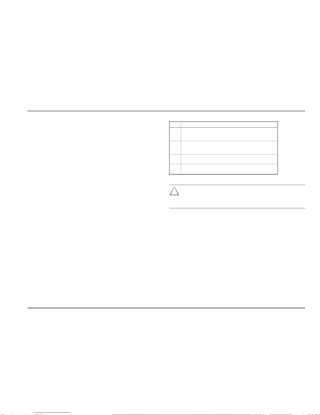
CAT
Definition
I
Measurements in electrical circuits which are not directly connected to
the mains: for example electrical systems in motor vehicles and
aircraft, batteries etc.
II
Measurements in electrical circuits which are electrically connected to
the low-voltage mains: via plug, e.g. in household, office and
laboratoryapplications
III
Measurements in building installations: stationary power consumers,
distributor terminals, devices connected permanently to the distributor
IV
Measurements at power sources for low-voltage installations:
meters, mains terminals, primary overvoltage protection devices
Applications and Classification of Devices Under Test
1.1 Classification of Devices Under Test
1.1.1 Protection Classes
Devices assigned to all of the following protection classes are
equipped with basic insulation, and provide for protection against
electrical shock by means of various additional precautions as well.
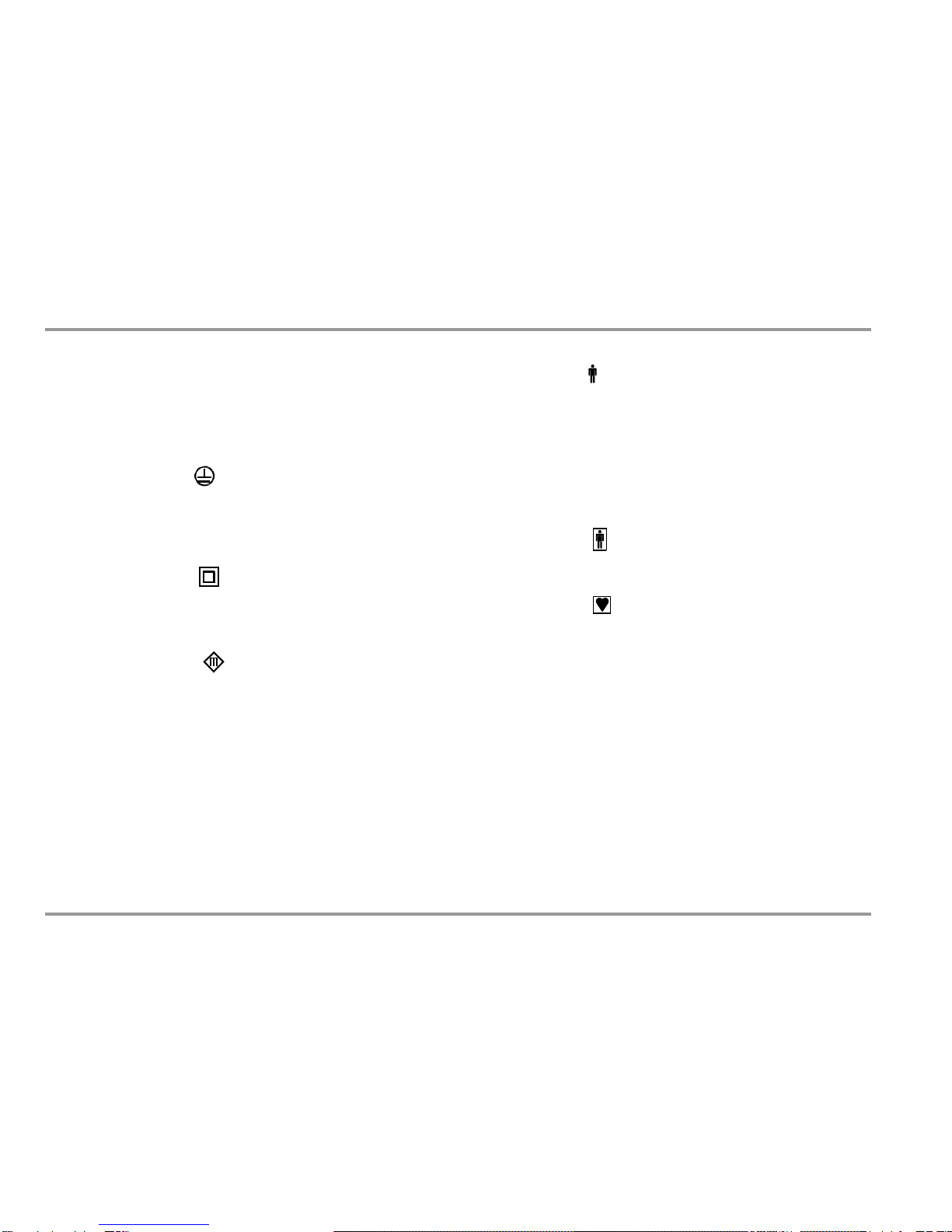
1.1.2 Applied Parts (electrical medical devices)
Type B Applied Parts
(body)
Devices of this type are suitable for both internal and external
patient applications, except for use in direct proximity to the heart.
These devices provide for adequate protection against shock,
especially as regards:
•
Reliable leakage current
•
Reliable protective conductor connection if utilized
Protection Class I Devices
Exposed, conductive parts are connected to the protective
conductor so that they are not charged with voltage if the basic
insulation should fail.
Type BF Applied Parts
(body float)
Same as type B, but with type F insulated applied parts.
Protection Class II Devices
These devices are equipped with double insulation or reinforced
insulation.
Type CF Applied Parts
(cardiac float)
Devices of this type are suitable for use directly at the heart. The
application part maynot be grounded.
Protection Class III Devices
These devices are powered with safety extra-low voltage (SELV).
Beyond this, no voltages are generated which exceed SELV.
These devices may not be connected to the mains.
Note: Only a visual inspection can be conducted for devices of this
protection class with the BC Biomedical SA-2500.
6
BC Biomedical

Safety Warnings
2
Safety Features and Precautions
Observe the following safety precautions:
•
The instrument may only be connected to electrical supply
systems with which conform to the valid safety
regulations
(e.g. IEC 60364, VDE 0100) and are protected with
a fuse or
circuit breaker with a maximum rating of 16 A.
Measurements within electrical systems are prohibited.
Be prepared for the occurrence of unexpected voltages at
devices under test (for example, capacitors may be
dangerously charged).
Make certain that the measurement cables are in proper
working
condition, e.g. no damage to insulation, no cracks in
cables or
plugs etc.
Insulation Resistance Measurement (alternative leakage current):
Testing is conducted with up to 500 V. Current limiting is
utilized (I < 10 mA), but if the terminals (L and N) are touched,
electrical shock may occur which could result in consequential
accidents.
Leakage Current Measurement
It is absolutely essential to assure that the device under test is
operated with line voltage during performance of leakage
current measurements. Exposed conductive parts may
conduct dangerous contact voltage during testing, and may
not under any circumstances be touched (mains power is
disconnected if leakage current exceeds approx. 10 mA).
Function Test
This instrument fulfills the requirements of applicable European
and national EC directives. This is confirmed by means of the CE
mark. A corresponding declaration of conformity can be
requested from BC Biomedical.
TheSA-2500 measuringinstrumenthasbeenmanufactured
and
tested in accordance with the following safety regulations:
IEC61010-1 / DIN EN 61010-1 / VDE 0411-1, DIN VDE 0404
IEC 61577 / EN 61577 / VDE 0413 part 1, 2 and 3
When used for its intended purpose, the safety of the user, the
measuring instrument and the device under test (electrical
equipment or electrical medical device) is assured.
Readtheoperatinginstructionscarefullyandcompletelybeforeplacing
yourmeasuringinstrumentintoservice.Followallinstructionscontained
therein.Makesurethattheoperatinginstructionsareavailable to all
usersof the instrument.
Tests may only be performed by qualified personnel, or under
the supervision and direction of qualified personnel. The user
must be instructed by qualified personnel in the execution and
evaluation of tests.
•
•
•
•
•
Note
Manufacturers and importers of electrical medical devices
must provide documentation for the performance of
maintenance by trained personnel.
•
!
Attention!
The function test may only be performed after the DUT has
successfully passed the safety test!
BC Biomedical
7
Safety Warnings
•
Power Consumers with High Inrush Current (> 16 A) –Function Test
(e.g. fluorescent tubes, halogen lamps, headlights etc.):
Observe the following instructions in order to prevent
excessive contact loads.
Meanings of Symbols on the Instrument
300 V CAT II
Maximumpermissiblevoltageandmeasuringcategory
between connections 1 through 4, the test socket and
ground
I
System with maximum 16 A nominal current
!
Attention!
Starting the Function Test
For reasons of safety, the device under test must be
switched off before the function test is started. This
precaution prevents inadvertent start-up of a device under
test which may represent a hazard during operation, e.g. a
cetrifuge.
Ending the Function Test
After completion of the function test, devices under test
must be turned off with their own switch –especially
devices with motors or other inductive loads.
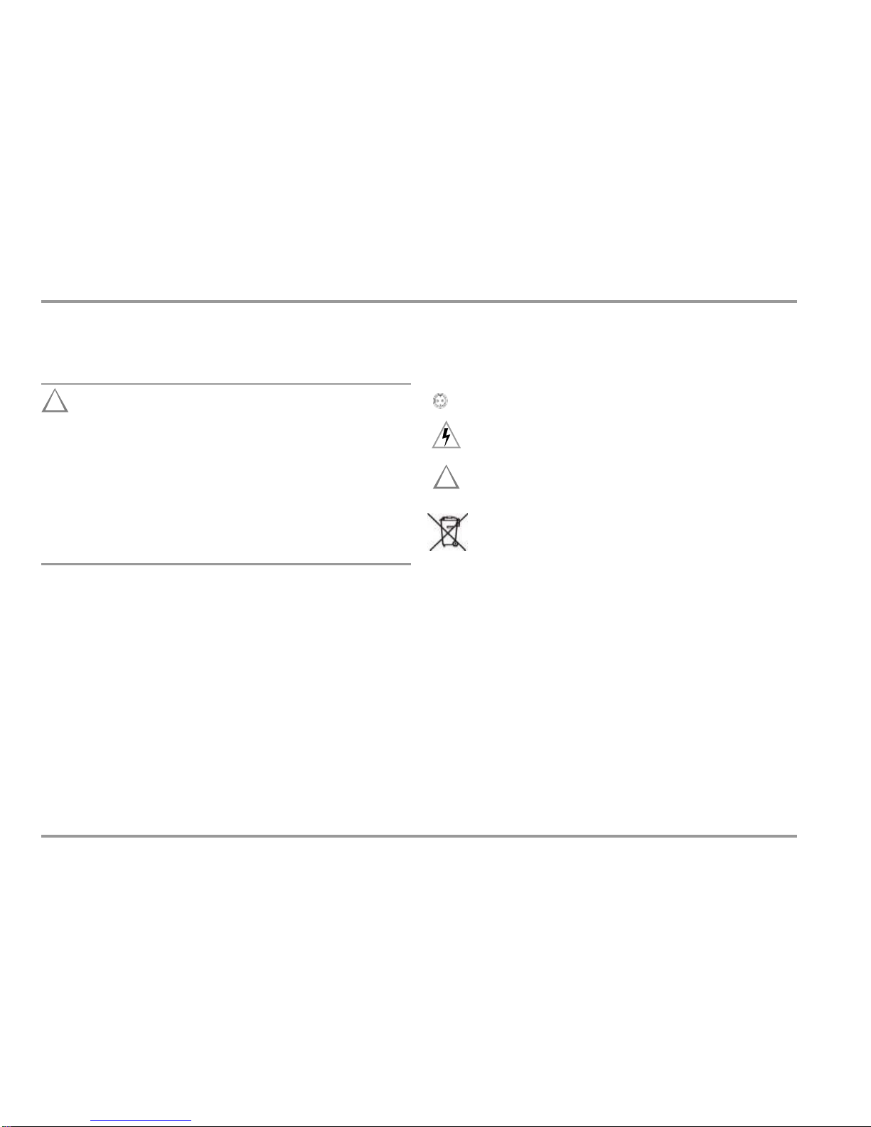
Warning regarding dangerous electrical voltage
Warning concerning a point of danger
(attention: observe documentation!)
!
Per European Council Directive WEEE
2012/19/EU, do not dispose of this product as
unsorted municipal waste.
The measuring instrument may not be used:
•
•
If it demonstrates visible damage
With damaged connector cables, measuring cables or
patient ports
If it no longer functions properly
•
In such cases, the instrument must be removed from operation
and secured against unintentional use.
8
BC Biomedical

Terminals
3
Terminals
Jacks 1 through 10 for Applied Parts
USB Slave, to PC
1
10
Standard Socket (test socket)
for connecting the DUT
S1
S2
nection
Connections for Probes
Insertthedoubleplugoftheprobeintosockets 1and2suchthat
the plug with the white ring makes contact with socket 1 (silver
ring).
If 2 probes are used: If the first probe is, for example, the 25 m cable
drum (1-2), the test point is contacted with the second probe (3-4).
1)
For a lot of measurements, the protective conductor of the
test socket is not connected with the protective conductor
of the mains terminal.
1)
4-wire measurement possible
2)
4-wire measurement not provided for, see ”Measuring and Storing an
Offset Value when Using a 2
nd
Probe” on page 15
BC Biomedical
9
Connection
Application
TopConnections
Standardsocket
Testsocket
Sockets 1 through 10
Applied parts connection
USB-SI
USB slave, to PC
Bottom Connections
Sockets 1 and 2
Test probe connection (max. 300 V CAT II)
Sockets 3/4 (green)
Terminal for second test probe
2)
(max. 300 V CAT II)
Inlet socket
Connection for supply power (90 to 240 V, 50 to 400 Hz)
MainsCon
Fuses
Initial Start-Up –Setup
4 Initial Start-Up
4.1 Connection to the Mains (90 to 240 V, 50 to 400 Hz)
➭
Connect the mains plug at the measuring instrument to the
mains power outlet.
4.1.1 Automatic Recognition of Mains Connection Errors
The measuring instrument’s protective conductor connection is
tested each time the start-stop key is pressed.
If a voltage of greater than 25 V is detected between the
protective conductor and the finger contact, no measurements
are possible. Disconnect the measuring instrument from the
mains immediately in the event of a mains connection error, and
arrange for the error to be corrected!
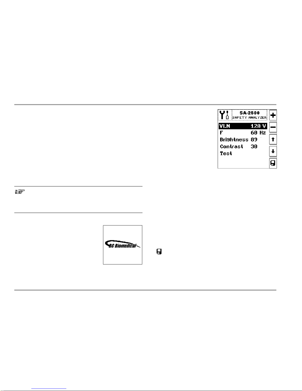
Selecting Nominal Line Voltage VLN
Measured values acquired by
means of leakage current mea-
surement are normalized to the
selected VLN voltage value. Line
voltage parameter VLN (100, 110,
115, 117, 120, 127, 220, 230,
240 or 250 V) can be selected
with the
keys, and adjusted
with the +/–keys. The voltage
value selected here is generated
by the measuring instrument for alternative measurement.
Setting Nominal Frequency
The frequency selected here is generated by the measuring in-
strument for alternative measurement of leakage current. Nominal
line frequency parameter F (50 or 60 Hz) can be selected with the
keys, and adjusted with the +/–keys. This setting is irrelevant
for direct measurement and differential current measurement.
Setting Brightness and Contrast
Brightness (1 ... 40 ... 100) and contrast (0 ... 40 ... 63) for the LCD panel
can be selected with the
keys, and adjusted with the +/–keys.
Activating Device Parameters
Changed values are permanently saved after acknowledging with
Note
Voltage at the mains protective conductor may cause
erroneous measured values during the measurement of
leakage current.
4.2 Switching the Measuring Instrument On
InitialWindow
The initial window shown at the right ap-
pears in the event of mains connection.
the
key. The display is then switched to the main menu. If the
setup menu is exited with the ESC key, the changed values only re-
main active until supply power to the instrument is interrupted.
Function Test
For testing the keys, LCD segments and the acoustic warning sig-
nal.
4.3 Configuring Device Parameters –Setup Menu
All of the settings which are required for operation of the
measuring instrument can be entered in the setup menu.
10
BC Biomedical

Local Operating Mode
Manual Test
5
Manually Triggered Measurements
Adjustable measuring parameters
are displayed as softkeys.
DIR
DIF
ALT
Direct measurement
Diff. current measurement
Alternative meas. method
PRINT:
Key for hardcopy functions
(inpreparation)
L/N
N/L
ESC:
Return to previous level
Mains polarity
ARROW
UP
HELP:
Access context sensitive help
Select measuring function
ARROW
DOWN:
MENU:
Access the main menu
(R
PE
measuringfunction)
Select measuring function
START
STOP: Start or stop measurement /
function test
SETUP:
Access the setup menu
–
Line voltage
–
Line Frequency
–
LCD brightness
–
LCD contrast
Contact Surface
For finger contact –PE potential check
Main Menu Display
!
Attention!
Remotecontrol ofthe SA-2500 should alwaysbe coordinated
with the user who is in contact with the measuring
instrument at the same time, for example in order to ex-
clude the possibility of contact hazards.
BC Biomedical
11
Operating Mode Display
–
Remote: highlighted display
–
Local: display not highlighted (see below)

Local Operating Mode
Manual Test
5.1 General Procedure
5.2
Overview
➭
➭
➭
Select the main menu: MENU key.
Select a menu function:
keys.
Depending upon the measuring function select either
–
Type of test current: DIR / DIF / ALT / DL key.
or
–
Protectionclassandtypeofconnection:PC1/PC2/FIX key.
Connect the device under test in accordance with the
previously selected type of test current.
14
➭
Depending upon the type of test current, it may be necessary to
use the probe.
The device under test is checked for short circuiting for all active
measurements during which the mains are connected to the test
socket (e.g. for leakage current measurements).
➭
Start the test with the START
STOP
key.
During measurement, a symbol representing a runner appears
at the upper left-hand corner instead of the measurement icon.
During measurement and after the measurement has been com-
pleted, measurement data can be read from the display.
➭
Ifnecessary,repeatthetestwithreversedmains
power
polarity:L/NN/Lkey.
➭
The display is returned to the main menu by pressing the ESC
key or the MENU key.
26
AP=appliedpart;PC1/2=protectionclassI/II;FIX=permanentconnection
12
BC Biomedical
Abbreviation
Measurement Type Parameter
Description
Measured Quantity /
Method
Type of
’Connection
Sockets:
Probe 1–2
APA ...K
Resistance Measurements
R PE
Protective conductor
resistance
PC1
l
Probe 1–2
Page
R INS
Insulationresistance
PC1
—
Page
16
PC2
l
Probe 1–2
FIX
Leakage Current Measurement
I E
Equipment leakage
current
DIR
Directmeasurement
Testsocket
l
AP A ... K
Probe 1–2
Page
18
DIF
Differential current
measurement
ALT
Alternativemeasurement
(alternative equipment
leakagecurrent)
I T
Touch current
DIR
Directmeasurement
Testsocket
l
Probe 1–2
Page
20
DIF
DifferentialCurrent
Measurement
ALT
Alternativemeasurement
(alternative equipment
leakagecurrent)
DL
Measurement with 2 probes
(cable drum at 1–2)
Probe 1–2
Probe 3–4
I P
Patient leakage current
DIR
Patient leakage current,
direct
Testsocket
l
AP A...K
Page
24
I AP
Appliedpartsleakage
current
DIR
Directmeasurement
(mainsat applied part)
Testsocket
l
AP A...K
Page
ALT
Alternative measurement
(altern.patientleakagecurrent)
Functions Tests
TEST
Voltage / Load current
Active/apparent power P/A
Power factor PF
Testsocket
Page
28

This page has been left blank to display the following measure-
ments on opposite pages for better clarity.
BC Biomedical
13
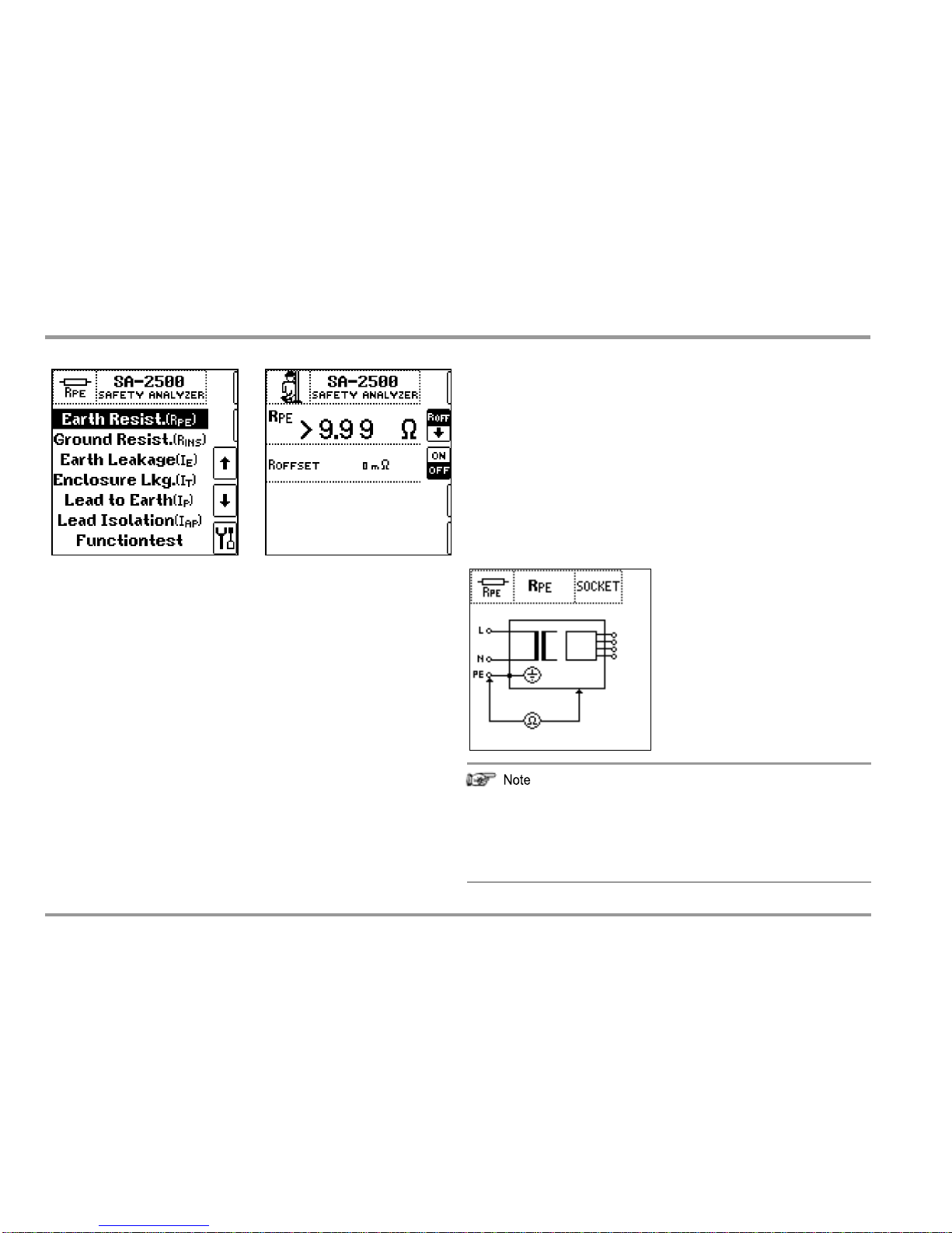
R
PE
ProtectiveConductorResistance
Measuring Method
Resistance is measured:
•
Betweeneachexposedconductivepart of the housing which
is connected to the protectiveconductor (probecontact) and
theearthingcontactsatthemainsand thedeviceplug(ifa
removablemainsconnectorcableisused).
•
Between the earthing contacts at the mains plug and the
earthing contacts at the device plug for device connector
cables
TestSocketConnection
Applications
Continuity and resistance of the protective conductor must be
measured.
Definition
Protectiveconductorresistanceistheresistanceofthe
connectionofaprotectionclassIdevice(PC1)betweenany
exposed conductiveparts whichareconnectedtothe protective
conductor and the protective contact at the mains plug or the
mains sideofthepermanentconnection.
Protective conductor resistance is the sum of the following
resistances:
The protective conductor of the test socket (which is not
connected with the protective conductor of the mains termi-
nal for this measurement) is permanently connected with
sockets 3 and 4 to which a second probe can be con-
nected.
•
•
•
Connector cable or device connector cable resistance
Contact resistance of the plug and terminal connections
Resistance of the extension cable
14
BC Biomedical

R
PE
ProtectiveConductorResistance
Measuring and Storing an Offset Value when Using a 2
nd
Probe
When a second probe is used which is connected to sockets 3
and 4, 4-wire measurements are not provided for. However, the
ohmic resistance of the cable for the second probe can be auto-
matically deducted from the measuring result by determining an
offset value. Please proceed as follows to this end:
➭
➭
Startthetest:PresstheSTART
STOPkey.
1
probe: Contact one of the conductive parts of the housing which is con-
nected to the protective conductor with the probe (socket 1–2).
2
probes: A cable drum or extension cable (socket 1–2) is contacted
with the reference point (e.g. overall earth electrode of a unit), the sec-
ond probe (socket 3-4) is contacted with the test point.
➭
Ð
Connect the two probes to sockets 1 and 2 or 3 and 4,
respectively. The probe extension cable or the probe
cable drum must generally be connected with sockets 1
and 2. Contact both probes with the same reference point.
This is equivalent to short-circuiting the two probes. The offset
value established in this way is retained by pressing the key on
the right (only for values < 2
), displayed briefly and will be
deducted from all future measuring results. You can store this
offset value, see key below.
After measuring the offset value, the latter can be per-
manently stored with the key on the right so that it is
available after switching the instrument on again.
Press the key on the right for loading a stored offset
value.
During measurement, the connector cable must only be moved to the ex-
tent that it is accessible during repair, modification or testing. If a change
in resistance occurs during the manual test step of the continuity test, it
must be assumed that the protective conductor is damaged, or that one
of the connector contacts is no longer in flawless condition.
➭
➭
➭
Measured values are displayed.
Endthetest:PresstheSTART
STOPkey.
Read the measured value and compare it with the table of
permissible limit values.
Ð
Examples of Maximum Permissible Limit Values for Protective Conductor
Resistance for Connector Cables with Lengths of up to 5 m
Ð
Cable
Only use this function if you work with extension cables.
When using different extension cables, the procedure
described above must principally be repeated.
Sequence
➭
Selectthetest:
keys.
➭
ConnecttheDUT tothetestsocket andconnecttheprobe.
BC Biomedical
15
Test
Standard
Test current
Open-
Circuit
Voltage
R
PE
Housing –
DevicePlug
R
PE
Housing –
Mains Plug
Connector
IEC 60601
IEC 61010
Production
Not defined
0.1
0.1
1.1
IEC 62353
(VDE0751-1)
> 200 mA
4 V < U
L
<
24 V
1.2
1.3
0.1
VDE 0701-
0702
—
0.3
+ 0.1
for each addi-
tional 7.5 m
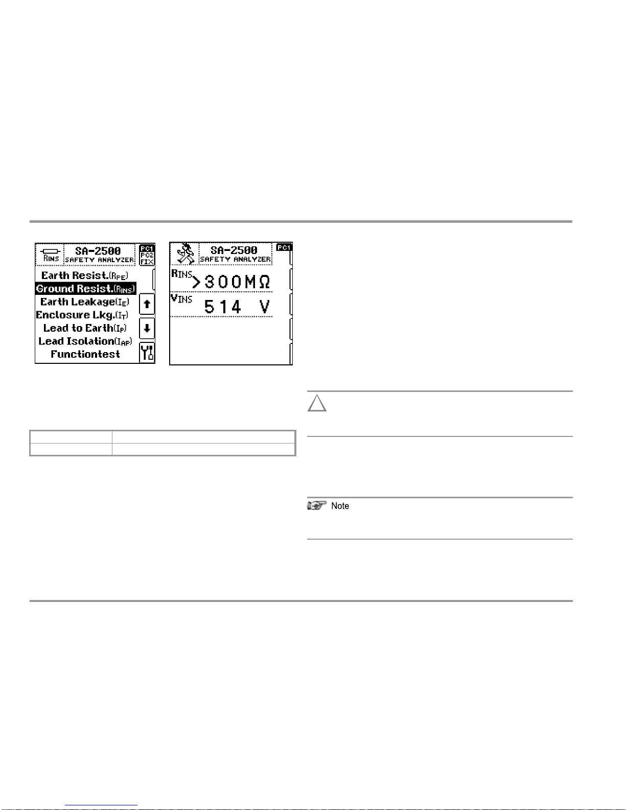
R
INS
InsulationResistance
Measuring Method
Protection Class I (PC1)
Insulation resistance is measured between short-circuited mains
terminals and the protective conductor.
Protection Class II (PC2)
Insulation resistance is measured between short-circuited mains
terminals and external conductive parts which can be contacted
with the probe.
Connection of Permanently Installed Protection Class I Devices
!
Attention!
Deactivate the electrical system which supplies power to
the device under test before connecting the test system!
Applications
Insulation resistance must be measured for:
➭
Remove the mains fuses from the device under test and
disconnectneutralconductorNinsidethedeviceundertest.
Connect the probe to phase conductor L at the device under
test in order to measure insulation resistance.
In order to assure that all insulation which is exposed to line
voltage is tested during this measurement, make sure that
switches, temperature regulators etc. are closed.
Definition
Insulation resistance is active resistance between the electrical
circuits of the device and its exposed conductive parts.
➭
ThePEcontact of thetestsocket isconnectedwiththe pro-
tective conductor of the mains terminal.
16
BC Biomedical
PC1: protection class l
Between L + N and PE
PC2: protection class ll
Between L + N and user accessible conductive parts

R
INS
Insulation Resistance
PC1 Connection
PC2 ConnectionI
Allswitches at the deviceunder test mustbeset tothe on posi-
tion during measurement of insulation resistance, including
temperature controlled switches and temperature regulators as
well. Measurement must be performed in all program steps for
devices equipped with program controllers.
➭
Start the test: Press the START
STOP
key.
!
Attention!
Testingisconducted with upto500 V.Currentlimiting is uti-
lized (I < 10 mA), but if the terminals (L and N) are touched,
electrical shock may occur which could result in conse-
quential accidents.
Permanent connection
Note: Open-circuit voltage is always greater than nominal voltage.
➭
PC2 connection:Contact exposed conductive parts with the
probe during measurement.
All measured values are displayed.
Endthetest:PresstheSTART
STOPkey.
Read the measured value and compare it with the table of
permissible limit values.
➭
➭
➭
Sequence
Protection class I devices: The protective conductor test must already
have been passed as a prerequisite for the insulation resistance test.
Examples of Minimum Permissible Limit Values for Insulation Resistance
➭
➭
Select the test:
keys.
Select the protection class and the type of connection:
PC1/PC2/FIX.key.
Connect the DUT to the test socket, and connect the probe if necessary.
➭
BC Biomedical
17
Test
Standard
TestVoltage
R
ISO
PC I
PC II
PC III
Heat
IEC 62353
(VDE 0751-1)
500 V
2 M
7 M
70 M
70 M
VDE0701-0702
1
M
2
M
0.25M
0.3 M

I
E
EquipmentLeakageCurrent(differentialcurrent–protectiveconductorcurrent–faultcurrent)
Definition of Alternative Measurement(alternative equipment leakage current)
Alternativeleakagecurrentis currentwhichflowsthroughthe
activeconductors of the device whichare connected toeach
other (L/N) to the protective conductor, or to the exposed,
conductive parts and the applied parts.
Direct Measurement Method
The device under test is operated with mains power. Current
which flows through the PE conductor to earth at the mains side
of the device connection is measured. The value which has been
adjusted to nominal line voltage is displayed (see section 4.3).
Theprotectiveconductorisineffectiveduringmeasurement!
Differential Current Measurement Method
The device under test is operated with mains power. The sum of
the momentary values of all currents which flow through all active
conductors (L/N) at the mains side of the device connection is
measured. The measurements must be performed with mains
plug polarity in both directions. The value which has been adjus-
ted to nominal line voltage is displayed (see section 4.3).
AlternativeMeasurementMethod(alternativeequipmentleakagecurrent)
The device under test is tested with the nominal voltage which
has been selected in the setup menu. Current which would flow
with this nominal voltage is displayed.
Type of Test Current Parameter
Applications
Equipment leakage current must be measured for all devices.
Definition of Equipment Leakage Current / Protective Conductor Current
IEC62353(VDE0751-1)
Current which flows from a power pack to ground via the protec-
tiveconductor, and viaexposedconductive partsof thehousing
and the applied parts.
Definition of Direct Measurement
Total amount of current which flows through the protective con-
ductor, probe and applied parts in the case of housings which are
isolated from ground.
Definition of Differential Current Measurement
Sum of instantaneous current values which flow via the L and N
conductors at the device mains connection. Differential current is
practically identical to fault current in the event of an error. Fault
current: Current which is caused by an insulation defect, and
which flows via the defective point.
–
DIR
–
DIF
–
ALT
Protectiveconductorcurrent,direct
Differential current
Alternative equipment leakage current
Mains Polarity Parameter
Polarity can be reversed for tests in accordance with the direct
and differential current methods.
18
BC Biomedical

I
E
EquipmentLeakageCurrent(differentialcurrent–protectiveconductorcurrent–faultcurrent)
Equipment Leakage Current with the Direct Measurement Method
Equipment Leakage Current with the Alternative Measurement Method
Sequence
The protective conductor is ineffective during measurement!
➭
➭
➭
➭
➭
➭
➭
➭
Select the test:
keys.
Connect the DUT to the test socket.
Select type of test current: DIR / DIF / ALT key.
Select mains polarity reversal: L/N / N/L key.
Start the test: Press the START
STOP key.
Measured values are displayed.
Endthetest:PresstheSTART
STOPkey.
Read the measured value and compare it with the table see bel.
EquipmentLeakageCurrentwiththeDifferential Current Measurement Method
Examples of Maximum Permissible Limit Values for Device Leakage
Current / Protective Conductor Current
BC Biomedical
19
Test Standard
Protec-
tionClass
Direct/DifferentialCur-
rent Measurement
Alternative Measurement
IEC 60601 3rd ed.
PC1
5 mA
10 mA
IEC 62353
(VDE 0751-1)
PC1
0.5mA
1 mA
PC2
0.1mA
0.5mA
VDE 0701/702
PC1
3.5mA
PC2
0.5mA

I
T
Touch Current –Testing for Absence of Voltage
Definition of Touch Current
Leakage current that flows from the housing or parts thereof –
with the exception of the patient ports –with which the user or the
patient may come into contact during use for intended purpose,
to ground or another part of the housing via an external
connection, except for the protective conductor.
Definition of Direct Measurement
Current which flows through the probe in the case of housings
which are isolated from ground.
Definition of Differential Current Measurement
Sum of instantaneous current values which flow via the L and N
conductors at the device mains connection. Differential current is
practically identical to fault current in the event of an error. Fault
current: Current which is caused by an insulation defect, and
which flows via the defective point.
Definition of Alternative Measurement (alternative equipment leakage
current)
Alternative leakage current is current which flows through the
active conductors of the device which are connected to each
other (L/N), to theexposed,conductiveparts.
Applications
ForprotectionclassIdevices,itmaybenecessarytoseparately
measureleakagecurrentfromexposedconductivepartswhich
are not connected to the protective conductor.
Only methods direct measurement and differential current mea-
surement can be used for devices for which isolation in the power
pack is not taken into consideration by the measurement (e.g. re-
sulting from a relay which is only closed in the operating state).
Leakage current measurement may only be performed at
protection class I devices after the protective conductor test has
been passed.
The device must be measured in all intended functional states
(e.g. switch positions) which influence leakage current. The
highest acquired value, as well as the corresponding function if
applicable, must be documented. The manufacturer’s
specifications must be adhered to.
20
BC Biomedical
Table of contents
Other BC Biomedical Measuring Instrument manuals

BC Biomedical
BC Biomedical SPO-2000 User manual

BC Biomedical
BC Biomedical DPM-2350 SERIES User manual

BC Biomedical
BC Biomedical USP-100A User manual

BC Biomedical
BC Biomedical USP-30 User manual

BC Biomedical
BC Biomedical PFC-3000 SERIES User manual

BC Biomedical
BC Biomedical SA-2010 User manual

BC Biomedical
BC Biomedical IPA-2000 User manual

BC Biomedical
BC Biomedical SPO-2000 User manual

BC Biomedical
BC Biomedical SA-2010S User manual

BC Biomedical
BC Biomedical DA-2006 User manual


