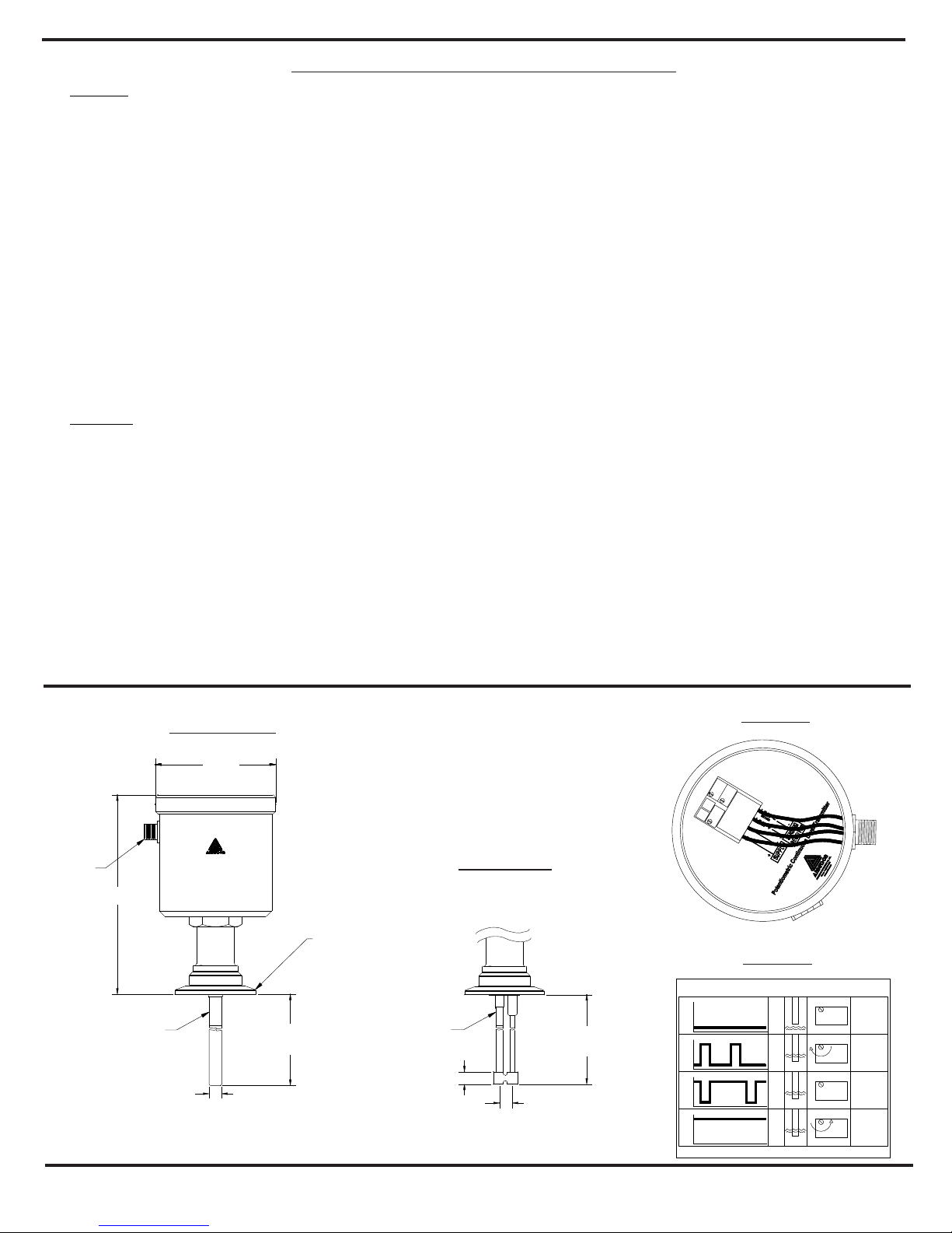
manuals.online logo
Brands
  1. Home
  2. •
  3. Brands
  4. •
  5. Anderson
  6. •
  7. Transmitter
  8. •
  9. Anderson LN Instruction Manual

Anderson LN Instruction Manual

2. Strip back 1-1/4” of outer sheathing, cut off any excess
wires, shield and ground. Strip off 1/4” insulation from
remaining four wires. It is not necessary or recommended
1. Insert cable through Pressing Screw, Compression
Ring, Seal Grommet, and Sleeve as shown below.
CABLE REQUIREMENTS
4 conductor, stranded, 18-24 AWG,
shielded with ground.
4-8mm (0.16-0.31”) Cable Sheath
OD.
Shown With
Cap Removed
3. Orient Connector end so that
center pin connecting screw is
horizontal facing right (see
detail).
4. Wire PWR + (red) wire to top-right
terminal, and PWR - (black) wire to
top-left terminal. Wire LOOP + (white) to
center terminal and LOOP - (green) to
bottom left terminal.
5. Screw on the Sleeve. Hand-tighten only.
6. Press the Seal Grommet into the Sleeve and
hand-tighten the Pressing Screw against the
compression ring.
7. Use a wrench to tighten the Pressing Screw
another 3/4 turn. Do not over-tighten!
Connector End
Section 1 - Field Wireable Connector
LN Potentiometric Level Transmitter
Quick Start Installation Guide
Rev. 2.1 Doc 1136 Page 1 of 2
Technical Bulletin
Anderson Instrument Co., Inc.
156 Auriesville Road
Fultonville, NY 12072
Phone: 518-922-5315 or 800-833-0081
www.anderson-negele.com
To install connector, simply line up key, press
into receptacle, and hand-tighten the
*Receptacle pins should be coated with
USDA approved dielectric grease to
Minimize possibility of corrosion.
Field Wireable Connector
+PWR (red) wire
-PWR (black) wire
Shield (clear or bare) wire
P/N: 42119B0000 (without cable)
P/N: 5662400000
*Dielectric Grease
Retaining Ring
Pin 1 - Red
(+PWR 18-36 VDC)
Pin 2 - Black
(-PWR)
DETAIL
Sleeve
Seal
Grommet
Compression
Ring
Pressing Screw
-2 included choose one to accommodate cable OD
Pin 3 - Green
(LOOP- Return) Pin 5 - White
(LOOP+)
Loop- return (green) wire
Loop+ (white) wire
Molded Cord Set - Heavy Duty
P/N: 42117F0025
42117F0050
42117F0100
Loop + (grey) wire
Loop - (blue) wire
Shield (clear or bare) wire
PWR- (white) wire
PWR+ (brown) wire
Molded Cord Set
Note: Green and White not used
on 2 wire devices.
Shield not connected to nut.
P/N: 42117K0025
42117K0050
42117K0100
+PWR (red) wire
-PWR (black) wire
Shield (clear or bare) wire
Loop- return (green) wire
Loop+ (white) wire
Figure 2
Figure 1
3.74”
INSERTION
LENGTH
6.1”
SHOWN WITH
2" TRI CLAMP
ANDERSON INSTRUMENT CO., INC.
WWW.ANDINST.COM
1-800-833-0081
MODELU
S/NU
INPUT 18-36 VDC
M12
CONNECTION
TEFLON COATING
2” for probe length < 20”
4” for probe length ≥ 20”
0.24” for probe length < 20”
0.39” for probe length ≥ 20” 0.59”
TEFLON COATING INSERTION
LENGTH
0.3”
2” for probe length < 20”
4” for probe length ≥ 20”
Rev. 2.1 Doc 1136 Page 2 of 2
Section 4 - Installation / Calibration Verification
Operation
• Probe may not be cut! Trimming the probe length will
disable the sensor and VOID warranty.
• The process connection must have electrical contact
with the tank, therefore LN’s must be clamped on
fitting for proper operation.
• Single probe LN's are suitable for installation in linear
metallic tanks with probe parallel to tank wall. Non-parallel
installation will increase reading error.
• Dual probe LN's are suitable for installation in
nonmetallic and/or non-linear tanks.
• Sensor probe must not touch tank wall.
• For accuracy and proper operation, measured media
should be homogeneous with respect to temperature
and conductivity. Media must have a conductivity of at
least 1 µS/cm.
• The LN is shipped calibrated to the bottom of the
Teflon® coating. Normally at installation, additional
adjustments are not required.
• A turndown of up to 30% below top of probe is possible
if 20mA output is desired at less than full rod height.
Follow SPAN ADJUST for this feature.
Calibration
Zero Adjust
1. Connect power supply as shown in Section 1.
2. Connect Digital MultiMeter to output. With empty
vessel (uncovered probe) signal output is 2.4mA.
3. Fill vessel until level contacts probe. Adjust OFFSET
until signal output is 4.0mA (see Fig. 1).
Span Adjust
1. Connect power supply as shown in Section 1.
2. Connect Digital MultiMeter to output.
3. Fill vessel until maximum level desired. Adjust SPAN
until signal output is 20.0mA (see Fig. 1).
Note:
• Probe will not measure in Teflon® coated zone. Maximum
level must be below the Teflon® zone.
• Max turn down is 30% of full probe length (including
Teflon® coated area) from the top e.g. 30” rod length
with 4” Teflon® coating may adjusted from 26” down to
21”.
• Span and Zero are normally non interactive however
significant turndown adjustment may require an
additional Re-Zero step.
Sensitivity
Typically adjustment is not required. If calibration is needed, perform
the following with the least conductive media:
1. Connect power supply as shown in Section 1.
2. Fill vessel until media level contacts probe.
3. Observe red LED labeled SENSITIVITY (see Fig. 2 LN
Sensitivity Table).
• If the LED remains off or only blinks on briefly, turn
SENSITIVITY clockwise.
• If the LED remains on continuously, turn
SENSITIVITY counterclockwise.
Note:
The objective is to achieve state 3 on the LN
Sensitivity Table. The red LED should be lit with a brief
off blink.
Single Probe
Dual Probe
Sensitivity Offset
Span
Sensitivity Power
OUTPUT PROBE
ON
OFF
ON
OFF
ON
OFF
ON
OFF
2.4
mA
4-20
mA
4-20
mA DO NOT
ADJUST
4-20
mA
LED
SENSITIVITY
ADJUSTMENT
DO NOT
ADJUST
EXPECTED
WITH NO
LIQUID
INCREASE
SENSITIVITY
TOO
SENSITIVE
OPTIMAL
State
1
2
3
4
LN Sensitivity Table

Other Anderson Transmitter manuals

Anderson DA2 User manual

Anderson

Anderson DA2 User manual

Anderson LD Series User manual

Anderson

Anderson LD Series User manual

Popular Transmitter manuals by other brands

HK Instruments AVT Series installation instructions

HK Instruments

HK Instruments AVT Series installation instructions

Doro Secure 271 quick start guide

Doro

Doro Secure 271 quick start guide

Lectrosonics SMa Series instruction manual

Lectrosonics

Lectrosonics SMa Series instruction manual

Greystone Energy Systems CD2DT Series installation instructions

Greystone Energy Systems

Greystone Energy Systems CD2DT Series installation instructions

Aigital 09S user manual

Aigital

Aigital 09S user manual

Shenzhen KingBoard Technology Co., Ltd. KBZ-818 Operation guide

Shenzhen KingBoard Technology Co., Ltd.

Shenzhen KingBoard Technology Co., Ltd. KBZ-818 Operation guide

Produal TEUFL Series user guide

Produal

Produal TEUFL Series user guide

Ashcroft KM41 installation instructions

Ashcroft

Ashcroft KM41 installation instructions

Rosemount 8712C product manual

Rosemount

Rosemount 8712C product manual

Siemens SITRANS LR110 operating instructions

Siemens

Siemens SITRANS LR110 operating instructions

Carson Reflex Wheel Pro 2 Telemetry 500500038 instruction manual

Carson

Carson Reflex Wheel Pro 2 Telemetry 500500038 instruction manual

KROHNE OPTIBAR DP 3050 Handbook

KROHNE

KROHNE OPTIBAR DP 3050 Handbook

Endress+Hauser Memograph CVM40 operating instructions

Endress+Hauser

Endress+Hauser Memograph CVM40 operating instructions

Televes 238201 user guide

Televes

Televes 238201 user guide

AssetScan ASB01 instructions

AssetScan

AssetScan ASB01 instructions

Crestron IM-WCVP Operation and installation guide

Crestron

Crestron IM-WCVP Operation and installation guide

LEGRAND MY HOME 883 31 installation instructions

LEGRAND

LEGRAND MY HOME 883 31 installation instructions

Baumer PBMN Series quick start guide

Baumer

Baumer PBMN Series quick start guide

manuals.online logo
manuals.online logoBrands
  • About & Mission
  • Contact us
  • Privacy Policy
  • Terms and Conditions

Copyright 2025 Manuals.Online. All Rights Reserved.