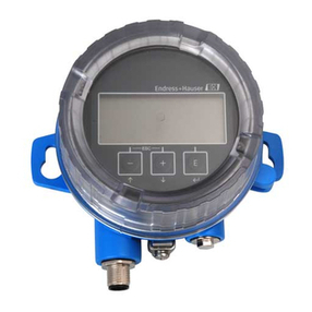
Endress+Hauser Memograph CVM40 User manual
Other Endress+Hauser Transmitter manuals
Endress+Hauser
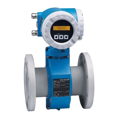
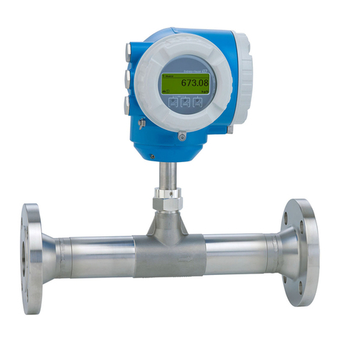
Endress+Hauser Promag Series User manual
Endress+Hauser
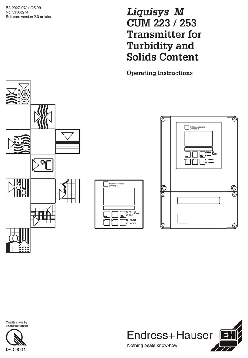
Endress+Hauser Proline 300 Technical specifications
Endress+Hauser
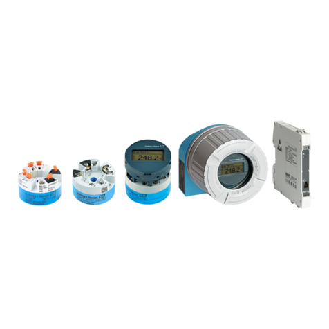
Endress+Hauser Liquisys M CUM 223 User manual
Endress+Hauser
Endress+Hauser iTEMP TMT71 Technical specifications
Endress+Hauser
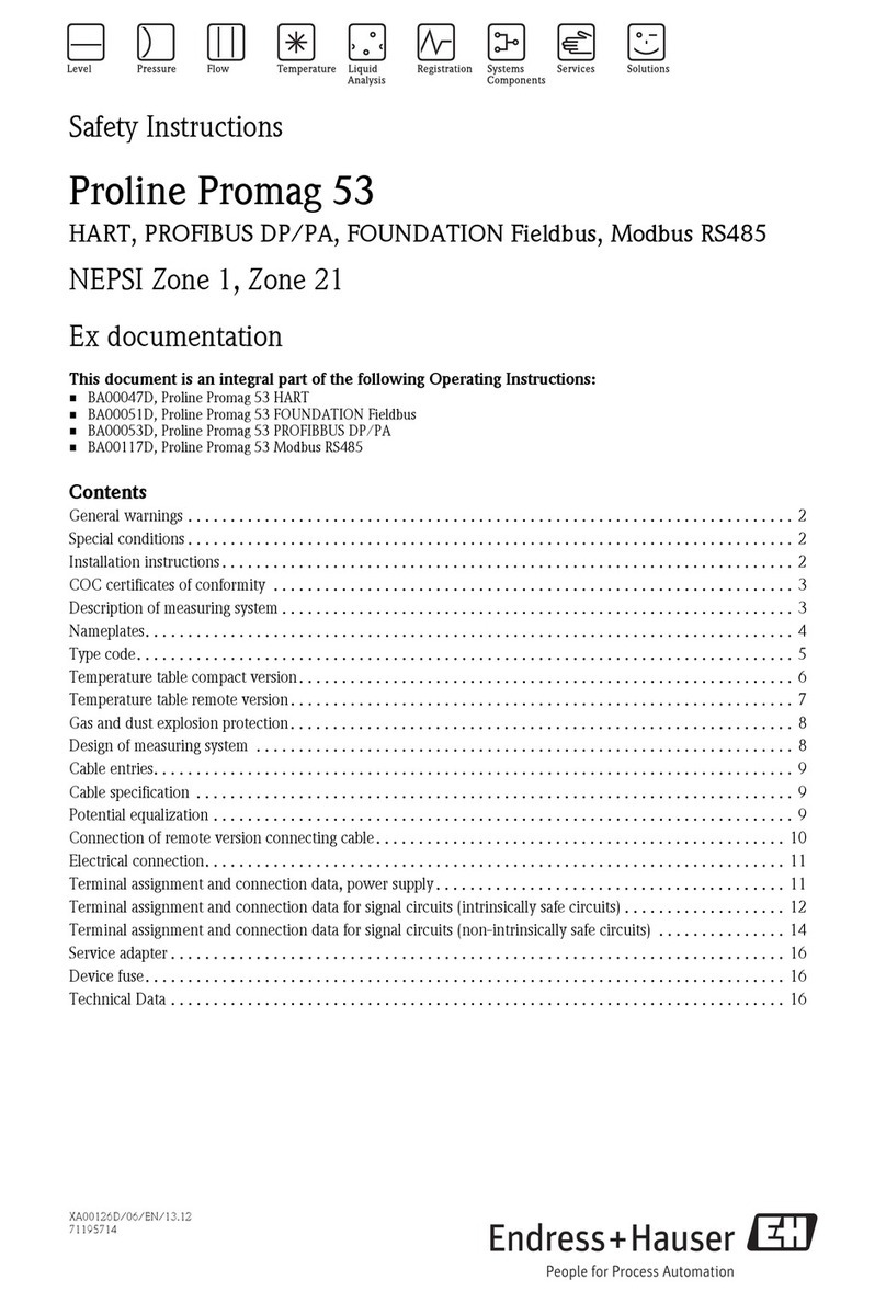
Endress+Hauser PROline promag 53 Installation instructions
Endress+Hauser
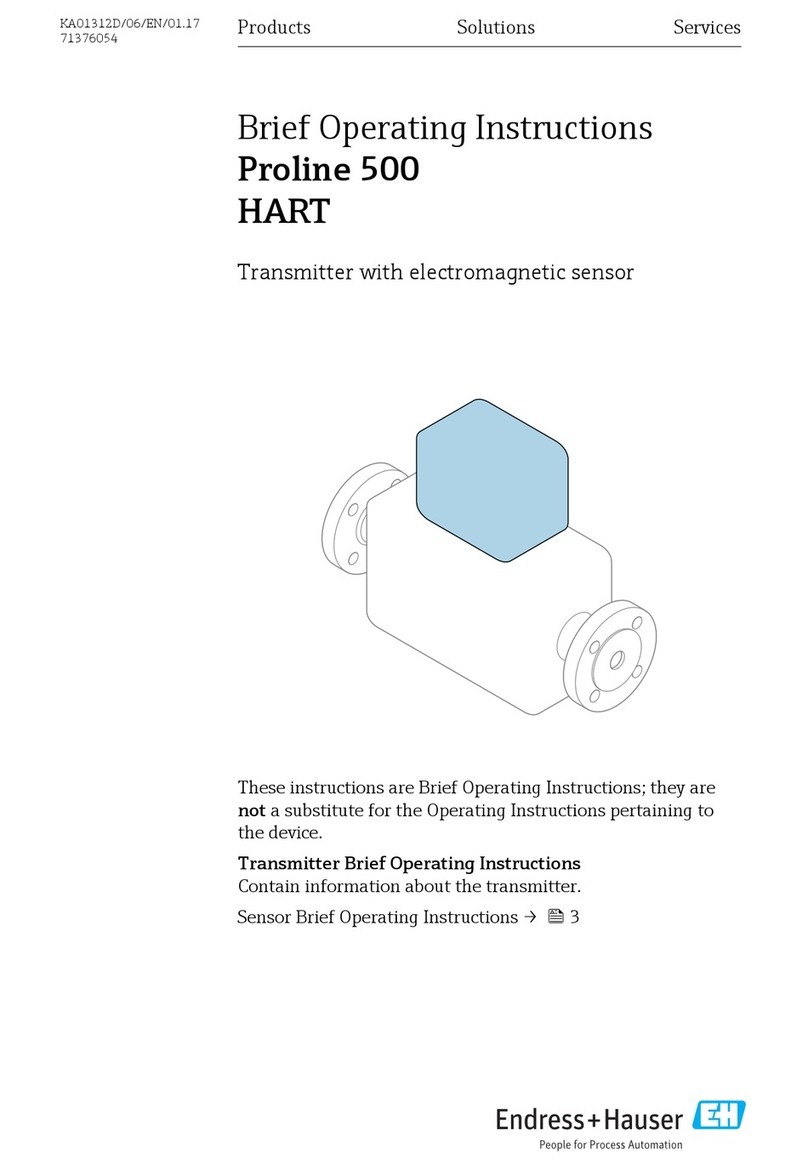
Endress+Hauser Proline 500 HART Technical specifications

Endress+Hauser
Endress+Hauser Proline 500 PROFIBUS PA Technical specifications
Endress+Hauser
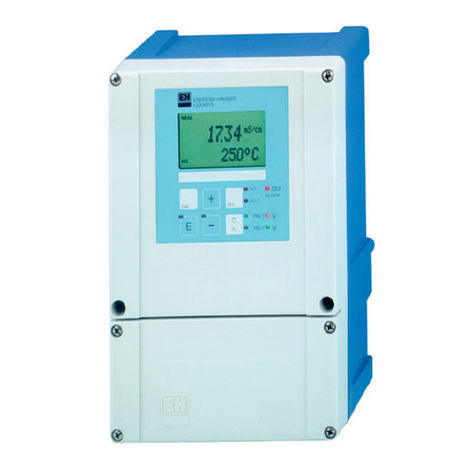
Endress+Hauser Liquisys M CLM223 User manual
Endress+Hauser
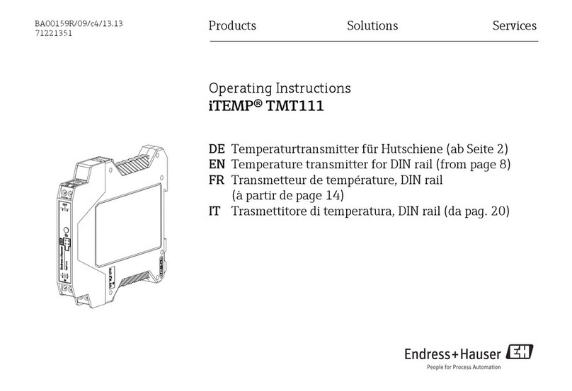
Endress+Hauser iTEMP TMT111 User manual
Endress+Hauser
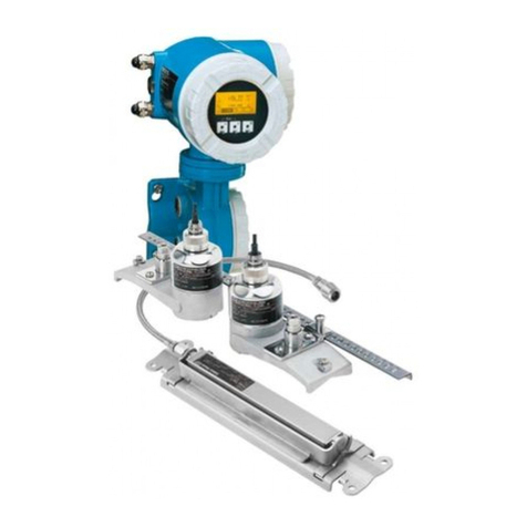
Endress+Hauser Proline Prosonic Flow 93 User manual
Endress+Hauser
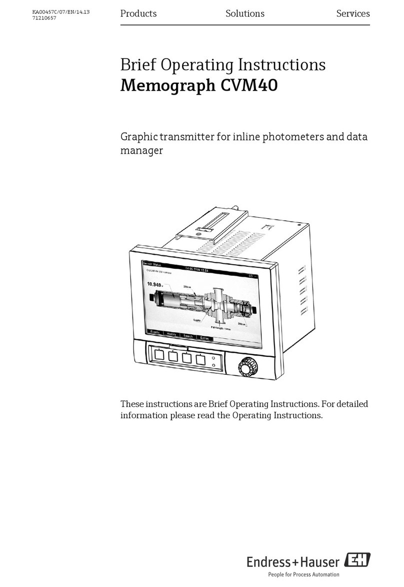
Endress+Hauser Memograph CVM40 Technical specifications
Endress+Hauser
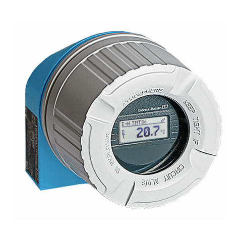
Endress+Hauser iTEMP TMT86 Technical specifications
Endress+Hauser
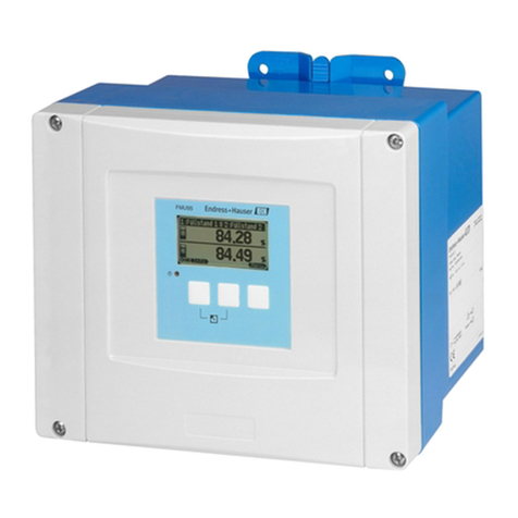
Endress+Hauser Prosonic S FMU95 User manual
Endress+Hauser
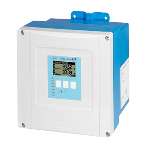
Endress+Hauser Prosonic S FMU90 User manual
Endress+Hauser
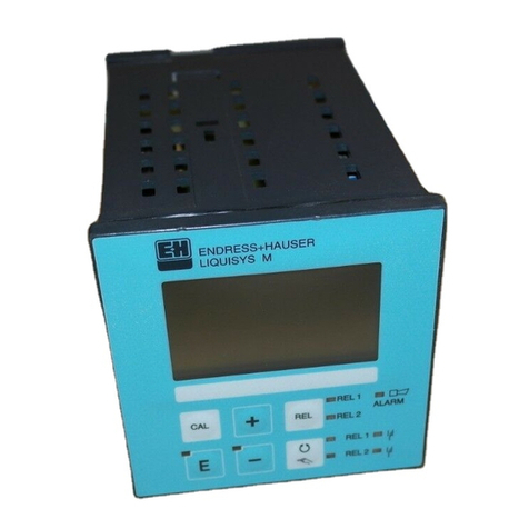
Endress+Hauser Liquisys M CLM 223 User manual
Endress+Hauser
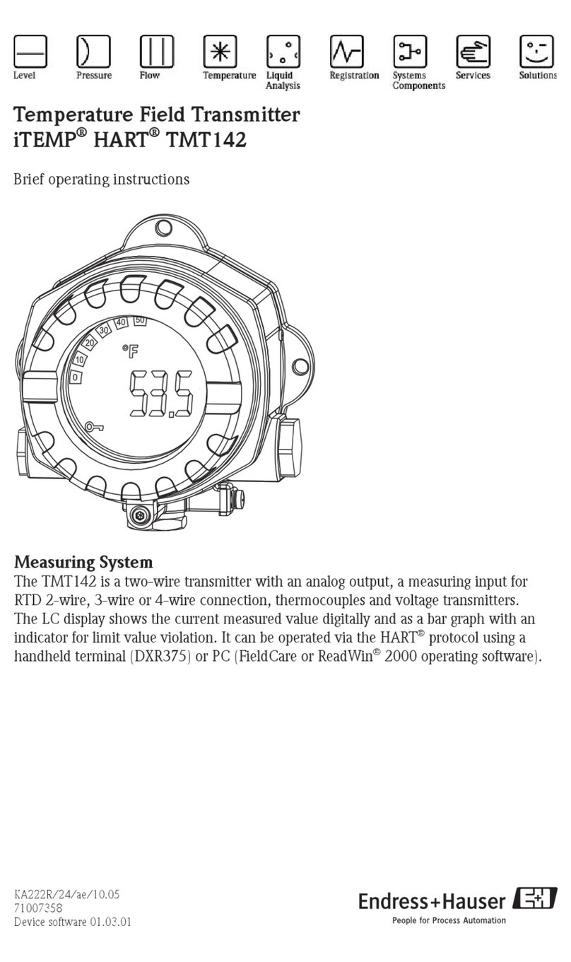
Endress+Hauser tmt142 Technical specifications
Endress+Hauser
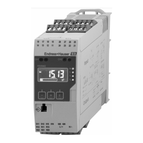
Endress+Hauser RMA42 User manual
Endress+Hauser
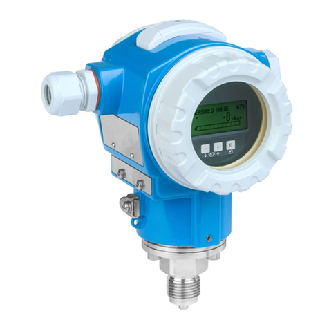
Endress+Hauser Cerabar S PMC71 User manual
Endress+Hauser
Endress+Hauser Flowmeter Proline 200 Technical specifications
Endress+Hauser
Endress+Hauser HART Flowmeter Proline 400 Technical specifications
Popular Transmitter manuals by other brands

Dejero
Dejero EnGo 3x manual

Rosemount
Rosemount 4600 Reference manual

Speaka Professional
Speaka Professional 2342740 operating instructions

trubomat
trubomat GAB 1000 instruction manual

Teledyne Analytical Instruments
Teledyne Analytical Instruments LXT-380 instructions

Rondish
Rondish UT-11 quick start guide
