Angelus 180S Operation and maintenance manual

Angelus 4900 Pacific Blvd. Los Angeles, CA 90058-2214 Tel: (323) 583-2171 1/1
Service Notices
Model 180S
1) Select the Bookmark option
2) Click on appropriate Service Notice
Service Notice Numbering and Tracking System
The following layout is using a single part number for reference
65L614 Rubber Plug
8 characters used as a "File Name" on the computer system.
060 14 001
Subdivision related to the part "14" which will continually increase as the number
of Lubrication Notices are created.
Type of part - Main Division, such as "14" for Lubrication or "44" for Shafts or "00" for an
assembled component.
Designates Seamer Model Number
Revisions to existing Service Notices will be as follows:The "File Name" will be duplicated on
the Service Notice with the latest revision level designated by a letter.
Example: 06014001"A". Revision levels on Service Notices are rare but can happen. The
Service Notice will provide remaining needed information.

ANGELUS SANITARY CAN MACHINE COMPANY
SERVICE NOTICE
Seaming Lever Cone Point Set Screw 32S826
104S816 104S816
Locknut Locknut
Seaming Roll
Adjustment Screws
28S826
* It is recommended to hold the Seaming Roll Adjustment Screw while
tightening 104S816 Locknuts.
180S Seaming Roll Lever Torque Specifications
Seaming Lever Cone Point Set Screw, number 32S826.
used to locate the Seaming Roll Lever on the Seaming Lever Shaft
should be tightened to 80 ft. lbs80 ft. lbs
80 ft. lbs80 ft. lbs
80 ft. lbs. before endplay ad ustments are
made.
Locknut, number 104S816,
used to clamp & hold the Seaming Roll Ad ustment Screw should
be tightened to approx. *45 ft. lbs*45 ft. lbs
*45 ft. lbs*45 ft. lbs
*45 ft. lbs. after Seaming Rolls have been
set.
5/21/91-18000001

ANGELUSSANITARYCANMACHINECOMPANY
SERVICE NOTICE
1 of 5
Complete Oil Change, 180S Seamer
The following procedure will drain all oil from the 180S seamer to insure all contami-
nates have been removed before new oil is installed.
A. Drain oil from the Upper Turret. Take out the Drain Plug located at
station no.1
NOTE:
EachSeamingSpindleis
heldintotheUpperTurretbya
BearingRetainerwithFaceSeal.
Bearingcavitieswillholdsome
oilandnotallowafulldrain.Three
and1/2quartswilldrainfromthe
Turret.Itholdssixquarts.
B. Drain Lower Turret.
Oil in the Lower Turret can be completely drained by taking out (6) pipe plugs located
between stations 2 & 3, 5 & 6, 8 & 9, 11 & 12, 14 & 15, and 17 & 18.
1/8 -27 pipe plugs are at this
location around the Lower
Turret.
11/10/90-18000002

ANGELUSSANITARYCANMACHINECOMPANY
SERVICE NOTICE
2 of 5
C. RemovebothServiceCoversfromthemachineandwipeclean*theUpperTurret
Housingarea.DisconnecttheoilreturnlinebelowtheHousingandflushitout
toremoveallcontaminates.
*Caution: When cleaning out the Housing area, it is very important to not use high
pressure hoses or any forced cleaning solutions inside this area. Water will enter the
Upper Turret, settling into bearing cavities, and will not be drained out through the
plug. If this accidently happens, all 18 Seaming Spindles will have to
come out to drain water.
D. Turn off air pressure supply to the Drive Case before disconnecting return line at
Lower Turret Guard.

ANGELUSSANITARYCANMACHINECOMPANY
SERVICE NOTICE
3 of 5
F. Drain oil from Filler Gear Drive Case.
Take out a 3/4" pipe plug
undertheFillerDriveClutch
Housing.
Take out a 1/2" pipe plug on
the bottom of this Drive Case.
E. Drain Drive Case.
Remove 1" pipe plug from the Drive Case Cover.

ANGELUSSANITARYCANMACHINECOMPANY
SERVICE NOTICE
4 of 5
G. Drain In-Motion Timer and Tail Shaft Assemblies.
Two 3/4" pipe plugs located under each of these.
H. Replace Filtration System Filter. Clean out Filter canister and install new
Filter. Drain oil reservoir and Clean out Water Separator

ANGELUSSANITARYCANMACHINECOMPANY
SERVICE NOTICE
5 of 5
Oil Refill Process.
Installalldrain plugs(usepipe sealant)beforerefilling oil.
1. Refill Upper Turret through the Rotating Union Guard on top of the
Machine. Pour the oil down the outside of the Rotating Union Support and
not down the center. Install (6) quarts of Aero-Shell W80 oil.
2. Fill Lower Turret through fill plug. Install 8 quarts Aero-Shell W80 oil.
3. Fill Drive Case through an opening on the side of the Base just below
Discharge side of Machine. Take off the Base Cover to do this. Drive Case
holds 21 1/2 quarts of Aero-Shell W80 oil.
4. Filler Drive and In-Motion Timer Housings will hold 4 1/2 quarts Aero-
Shell W80 oil. Both these units can be filled at the same time through an
openinginthe FillerDriveClutchHousing.
5. Fill Tail Shaft assembly with 1 quart of Aero-Shell W-80 oil. There is a fill
plug on top of this assembly.
5. Refill Filler Drive Gear Case with 3 quarts of 80/90W Lubriplate. Fill
plugs are located on top of this assembly.
6. Refill Trabon oil Reservoir with 7 quarts Aero-Shell W-80 oil.
7. RefillFilter Canister with6 quarts Aero-ShellW-80.
Note: If Food Grade Oil is required then use Chevron FM105X. Tube lines
from the oil pump will consume a certain amount of oil. Listed are
quantities of oil per foot.
A 1/2" Tube line holds 0.04 quarts of oil / Foot.
3/4" line holds 0.1 qts./ft.
1.0" line holds 0.16 qts./ft.

ANGELUS SANITARY CAN MACHINE COMPANY
SERVICE NOTICE
8/31/04-18000003
Model 180S Seaming Rolls
with
Ceramic Ball BearingAssembly
InstallationRequirements

ANGELUS SANITARY CAN MACHINE COMPANY
SERVICE NOTICE
8/31/04-18000003
LUBRICATIONREQUIREMENTS:CeramicBallBearingsassembledwithintheSeamingRollandmountedreadyforproduction,
shouldonlyrequireoneshotofgreasefromahandgreasegun foreachassembly.Ifmorethanoneshotof greaseisinstalled,the
ceramic ball bearing will expel excess grease out of the assembly.
Suggestedlubricationintervals=every72hoursw/N.L.G.I.TypeOgreaseor1shotofgreaseaftersanitationtoremovewater
fromtheSeamingRoll.
Seaming Roll with Ceramic BearingAssembly
Installation Sequence for 180S Seamers

Angelus 4900 Pacific Blvd. Los Angeles, CA 90058-2214 Tel: (323) 583-2171 1/5
18014001 - 11/7/05
Service Notice
Subject:
180S Gravity Feed Lubricator for Can Feed Chain
Purpose:
Minimize expendable oil loss
Benefit:
The Gravity Feed Lubricator has substantial advantages over the existing sprocket lubricator.
The Gravity Feed Lubricator is a separate unit compared to the traditional chain sprocket lubri-
cator line fed by the automatic oil lubrication system. The Gravity Feed Lubricator does not
drain the oil recovery system, thus preventing oil loss. The Gravity Feed Lubricator can utilize a
lighter and less expensive oil.
Description:
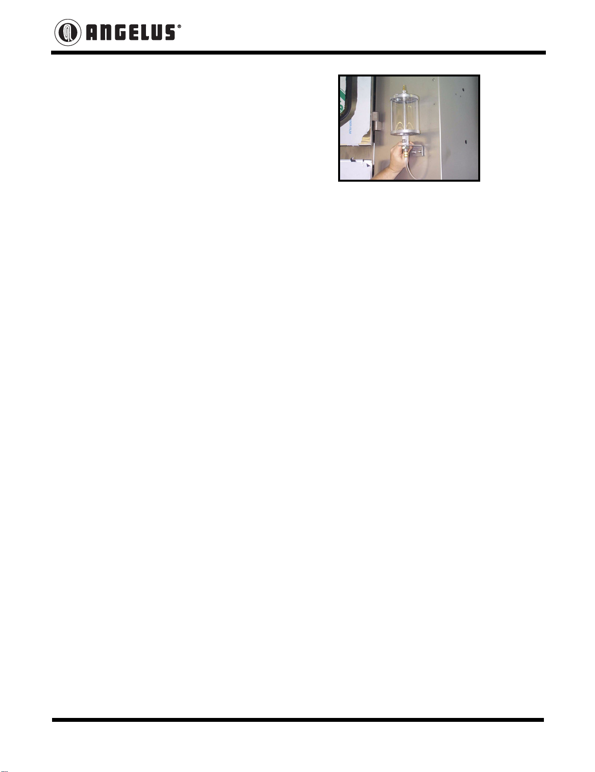
The Gravity Feed Lubricator consist of a oil canister with electrical solenoid mounted on the
outside top of enclosure for quick level visibility and plumbed by stainless steel line through
enclosure to the sprocket. The Gravity Feed Lubricator solenoid is programmed to operate
during “Jog” or “Run” commands only.
Availability:
Available for purchase per Parts List 121LM158.03.
Installation Procedure:
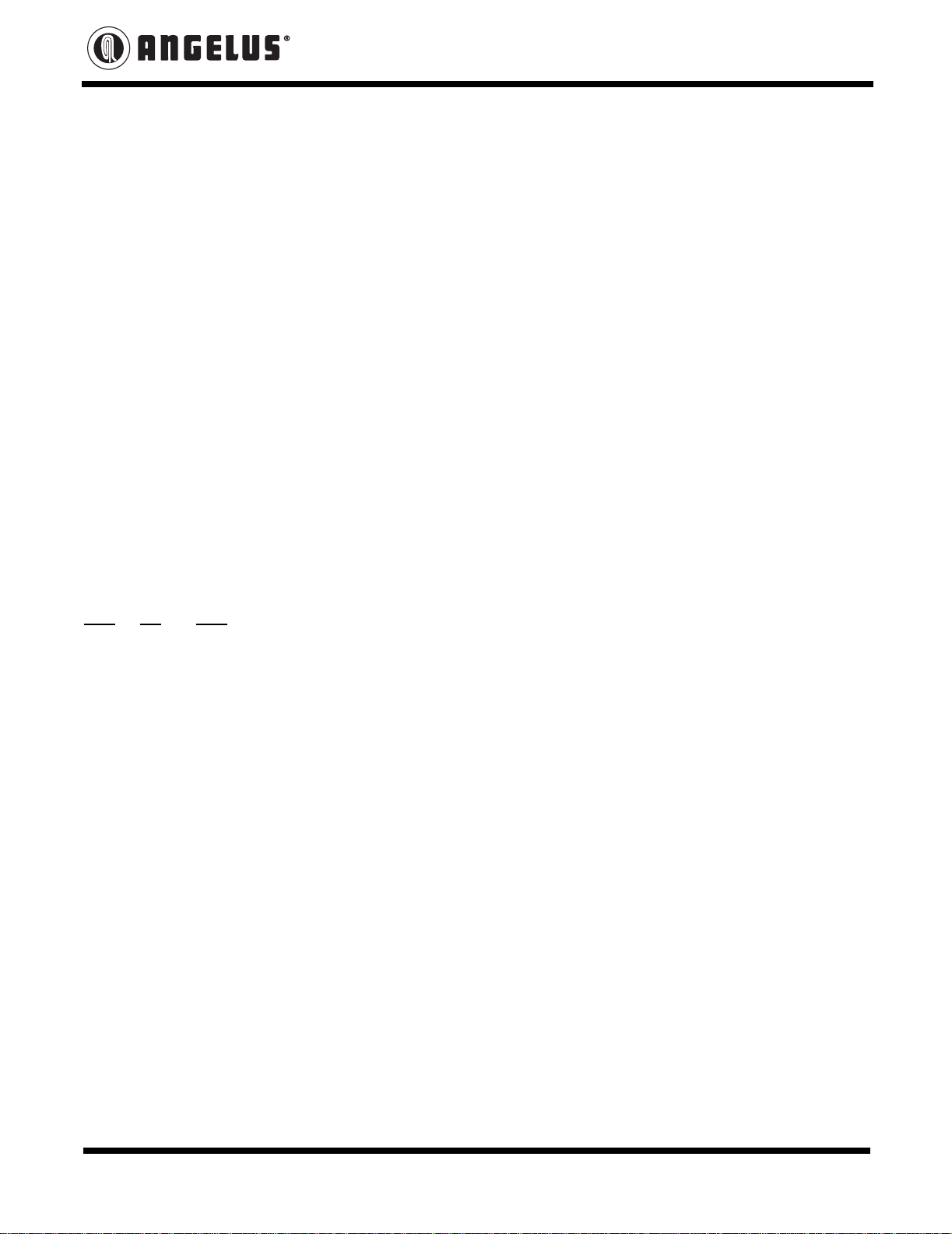
Divert the existing “Y” Feed Sprocket Line into “P” Lower Chuck Cam Line. Use Pipe Thread
Compound (PST) on all connections.
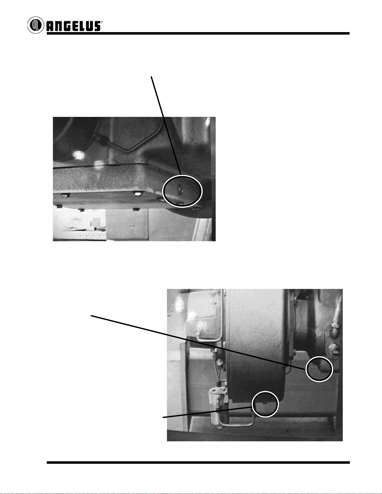
• Remove lines “Y” and “P” and temporary identify lines “Y” or “P” (See Fig. 1)
• Remove straight fittings from the base (See Fig. 1)
• Install 1/8 close nipple, 1/8 tee, and straight fitting into “P” designate in base (See Fig. 3)
• Install 1/8 close nipple and 1/8 elbow into tee (See Fig. 3)
• Install 1/8 plug in “Y” designate in base (See Fig. 3)
• Reinstall lines by cutting to fit. (See Fig. 3)
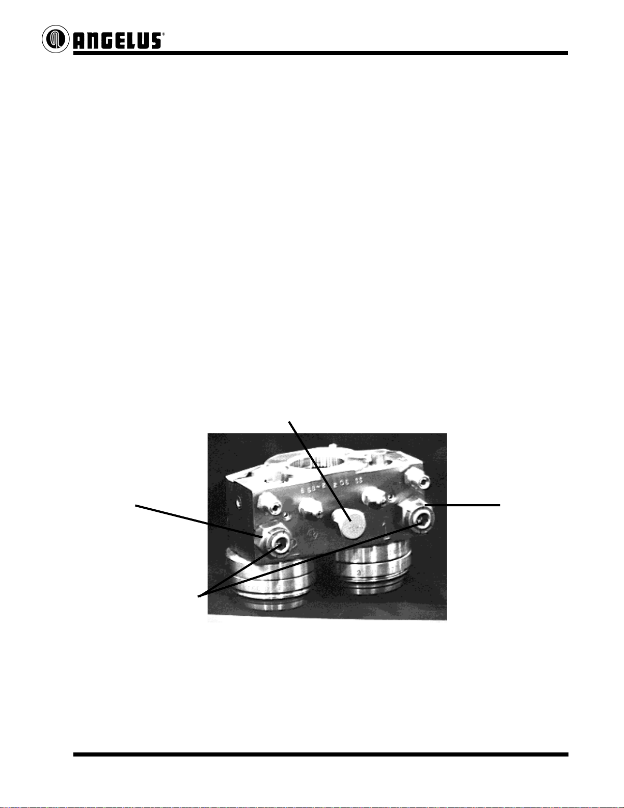
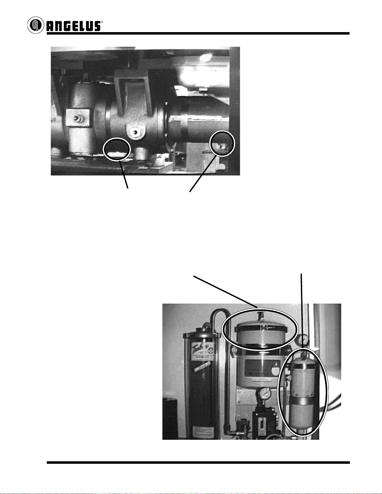
• Remove existing sprocket lubricator line and install 1/8 plug. (See Fig. 4)
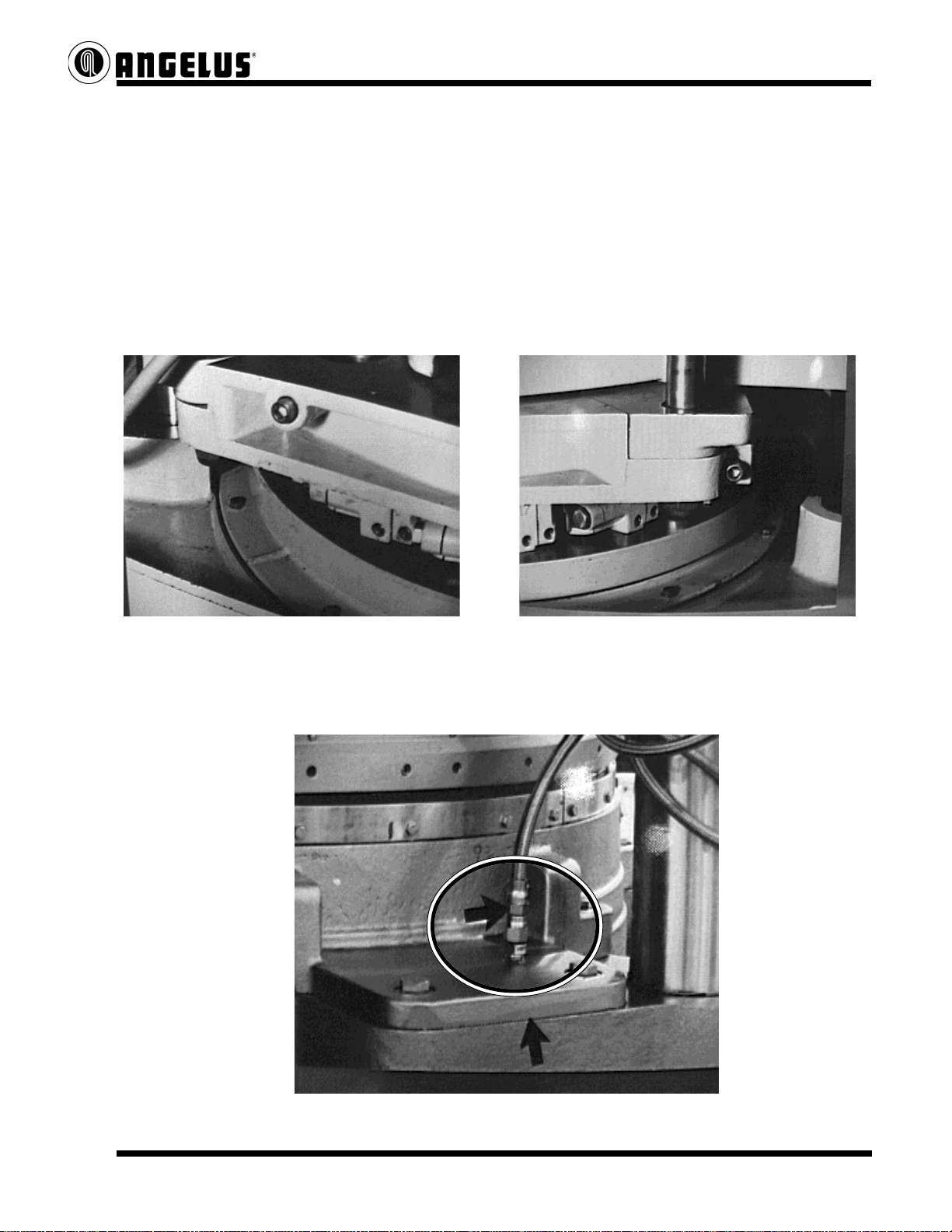
• Install Gravity Feed Lubricator (See Fig. 6)
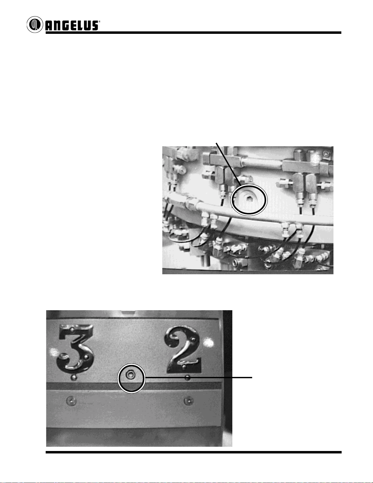
• Modify 262S854 feed sprocket guard per the following illustrations. (See Fig. 7)
• Electrical Programming Changes - Connect chain oiler solenoid to a unused 24VDC output.
In PLC program add a line of logic. Program “Jog Command” bit parallel with “Run
Command” bit to energize Gravity Feed Lubricator.

Angelus 4900 Pacific Blvd. Los Angeles, CA 90058-2214 Tel: (323) 583-2171 2/5
18014001 - 11/7/05
Service Notice
Fig. 1 - 180S without Gravity Feed Lubricator
Fig. 2 180S without Gravity Feed Lubricator
Fig. 3 - 180S with Gravity Feed Lubricator
Fig. 4 - 180S with Gravity Feed Lubricator
“P” Lower Chuck Cam Line
“Y” Feed Sprocket Line
Plugged Feed Sprocket Line
Line Diversion
“P” Lower Chuck Cam Line
“Y” Feed Sprocket Line

Angelus 4900 Pacific Blvd. Los Angeles, CA 90058-2214 Tel: (323) 583-2171 3/5
18014001 - 11/7/05
Service Notice
Fig. 5 - Lube Line Diversion
Ref. Data Sheet G180.156-A

Angelus 4900 Pacific Blvd. Los Angeles, CA 90058-2214 Tel: (323) 583-2171 4/5
18014001 - 11/7/05
Service Notice
Fig. 6 - Lubricator Assembly
Ref. Data Sheet G180.156-A

Angelus 4900 Pacific Blvd. Los Angeles, CA 90058-2214 Tel: (323) 583-2171 5/5
18014001 - 11/7/05
Service Notice
Fig. 7 - 262S854 Feed Sprocket Guard Modification
Ref. Data Sheet G180.156-A

Angelus 4900 Pacific Blvd. Los Angeles, CA 90058-2214 Tel: (323) 583-2171 5/5
18014001 - 11/7/05
Service Notice
Fig. 7 - 262S854 Feed Sprocket Guard Modification
Ref. Data Sheet G180.156-A

Angelus 4900 Pacific Blvd. Los Angeles, CA 90058-2214 Tel: (323) 583-2171 1/1
18015001 - 8/9/06
Service Notice
Subject:
180S Seamers - Filler Drive Safety Clutch Oil Seal (26S815)
Purpose:
To give customers notification regarding Angelus in house overhauls of Filler Drive In Motion
Timer & Filler Drive Safety Clutch Assemblies.
• The oil seal (26S815) will be shipped separately or uninstalled.
• It is the customers responsibility to install the oil seal (filler gear box applications only).
Description:
Filler Gear Box Applications: The oil seal (26S815) located within the 17S843 clutch housing
prevents intermixing of the filler gear box gear lube and clutch housing/tailshaft seamer oil.
Filler Belt Drive Applications: The oil seal (26S815) is not to be installed because it would
restrict seamer oil to the filler belt drive assembly causing bearing damage.
17S843 Clutch Housing
Filler Gear Box
26S815 Oil Seal Installed Only on Filler
Gear Box Applications
Filler Belt Drive
17S843 Clutch Housing

ANGELUS SANITARY CAN MACHINE COMPANY
SERVICE NOTICE
1
Model 180S Main Drive Shaft
Locknut 192S816 Requirements.
Calculated Pinion location shims must be
installed prior to final assembly and
torquing the Locknut.
1. Install the Bearing Carrier, Tapered
Roller Bearing Assembly and the
Clamp Locknut 192S816.
Use Spanner #J-13168 to torque the
Locknut to 250 ft. lbs.
NOTE: These photos show the Bearing
Retainer mounted in the bore. The Fixture is
designed to be used with the Carrier in or
out, although the Torquing Fixture Flange is
more stable with the Carrier out of the bore
when applying this amount of torque.
2. Install the Nut Clamp using (4) M4 x
16mm L. Soc. Hd. Screws. Use Blue
#243 Loctite on the screw threads.
3. After tightening the Locknut, install
Bearing Retainer 76S817, always use
Parker Super Lube on O-Rings,
ensure that the oil ports line up and
use (4) M10-1.5 X 70mm L. Soc.
Capscrews. Use Blue #243 Loctite on
screw threads.
Locknut Fixture #J-13168
Locknut Clamp, use Blue loctite
#243 on the M4 screws
Torque the Locknut to a required 250 ft. lbs.
18016001-12/15/98

ANGELUS SANITARY CAN MACHINE COMPANY
SERVICE NOTICE
1
10/7/99-18020001
Knockout Pad Adjustment Procedures
204 diameter covers only!
Model 180S Seamer must be equipped with the following;
204 cover dia. Knockout Pad no. F 056L841
Knockout Cam no. F 017S820
Lower Chuck Cam no. F 01S820
Adjusting Umbrella style Knockout Pads
1st. Insure that the Lower Chuck Cam is located
correctly, the Lower Chuck Plate plane is
within tolerance and the Seamer Pin Height
is correct.
2nd Measure the countersink depth on several
covers.
Example: .270
3rd Measure the Knockout Pad contact area
of the cover on the same set of covers.
Average these dimensions.
Example: .155
Countersink depth measurement of cover.
Knockout Pad contact area of
the Umbrella style Pad
Using a Countersink Gauge to
measure the Pad contact area.

ANGELUS SANITARY CAN MACHINE COMPANY
SERVICE NOTICE
2
10/7/99-18020001
4th. Subtract the Pad contact dimension, .155 from the countersink dimension, .270
Equals: .115
5th. Measure and add the Knockout Pad Offset
depth .160 of an inch to the above result.
Equals: .275
6th. Add .080 of an inch to the
above result in step 5.
Equals: .355 of an inch
7th. Add .355 to the Seamer Pin Height.
Example: 4.500 + .355 = 4.855
8th Place each station at the Timing Pin located
on the Lower Turret Guard.
Adjust the Knockout Pad at all stations
to obtain 4.855 inches from the offset area
of the Pad down to the Lower Chuck Plate.
Secure 1/2-20 Jam Nuts securely.
9th Adjust the Discharge side of the Knockout
Cam radially.
Rotate the Seaming Turret around, with a
seamed can and correct internal pressure, and Adjust Knockout Pad height
stop at the point where the seamed can has with an Inside Micrometer.
just released from the Seaming Chuck. Position
the Knockout Cam-Discharge radially until a .010 feeler gauge slips between the can and
Lower Chuck Plate. Secure the Cam.
NOTE: Set Knockout Pads measuring from Lower Chuck Plate up to the Offset area of the Pad.
Set Knockout Pad height when each station is positioned at the Timing Pin located on the
Lower Turret Guard.
Check can and cover control during the rise up to the Seaming Chuck. When the cam
is adjusted correctly, one should not be able to lift the can and cover up away from
the Lower Chuck Plate during the entire duration or cam rise, but still be able to turn
the can freely without any binding or pressure from above.
Knockout Pad Offset measurement
equals .160 of an inch

ANGELUS SANITARY CAN MACHINE COMPANY
SERVICE NOTICE
VARIABLE SPEED INCHING MECHANISM "VARIATOR PART NO. 5S822"
RECOMMENDATIONS:
1. DO NOT START THIS MECHANISM AT FULL 90 CANS/MINUTE SPEED.
2. DO NOT REVERSE DIRECTION OF MOTOR BEFORE FIRST BRINGING SEAMER TO
A COMPLETE STOP.
3. BE CERTAIN THAT THE TOOTH CLUTCH IS PERIODICALLY CHECKED FOR THE
PROPER .015" GAP AND OPERATION OF CLUTCH IS NORMAL.
4. ALWAYS MAINTAIN PROPER OIL LEVELS AND USE RECOMMENDED LUBRICANTS.
CAUTION: THIS UNIT IS A HYDRAULIC PUMP AND WILL NOT FUNCTION PROPERLY WITH AN
INADAQUATE OIL LEVEL. THIS COMPLETE UNIT IS DESIGNED FOR
MAINTENANCE ON THE SEAMER AND NOT TO BE USED FOR PRODUCTION OR
FOR CLEARING CAN JAMS.
IMPORTANT NOTICE:
LIMITER DEVICES
ROTATION OF THE VARIATOR CAN BE LOCKED OUT IN EITHER DIRECTION. REVERSE
DIRECTION IS LOCKED OUT AT THE FACTORY AND ONLY MOTOR DIRECTION
ALLOWS REVERSE ACTION.
TO USE ROTATION LIMITERS,
1. ADJUST THE VARIATOR TO THE REQUIRED MAXIMUM SPEED OR TO ZERO
R.P.M. IF A DIRECTION OF ROTATION IS TO BE ELIMINATED.
2. LOOSEN THE LOCKNUT ON THE APPROPRIATE ROTATION LIMITER, TURN THE
ROTATION LIMITER UNTIL IT BOTTOMS OUT AGAINST THE ADJUSTING
MECHANISM AND RETIGHTEN THE LOCKNUT.
VIEW OF VARIATOR IS FROM THE
OUTPUT SHAFT END.
ITEMS 1 & 4 = LOCKNUTS
ITEMS 2 & 3 = ROTATION LIMITERS
CLOCKWISE ROTATION LIMITER COUNTERCLOCKWISE
ROTATION LIMITER
123
4
5/20/91-18022001
Table of contents
Popular Industrial Equipment manuals by other brands

Felder
Felder ERM 1050 operating manual

SUHNER
SUHNER ROTOmaster 12, ROTOmaster 15 Technical document

Power Master
Power Master 8-37101 instruction sheet

Harmonic Drive
Harmonic Drive SHG Series manual

Ebmpapst
Ebmpapst R1G133-AA17-02 operating instructions

Tek-Trol
Tek-Trol TEK-DP 1630A Series instruction manual