Content
............................................................................................. 2
............................................................................................... 4
................................................................................................ 8
....................................................................................... 11
Warranty .................................................................................................. 12
Appendix ................................................................................................. 13
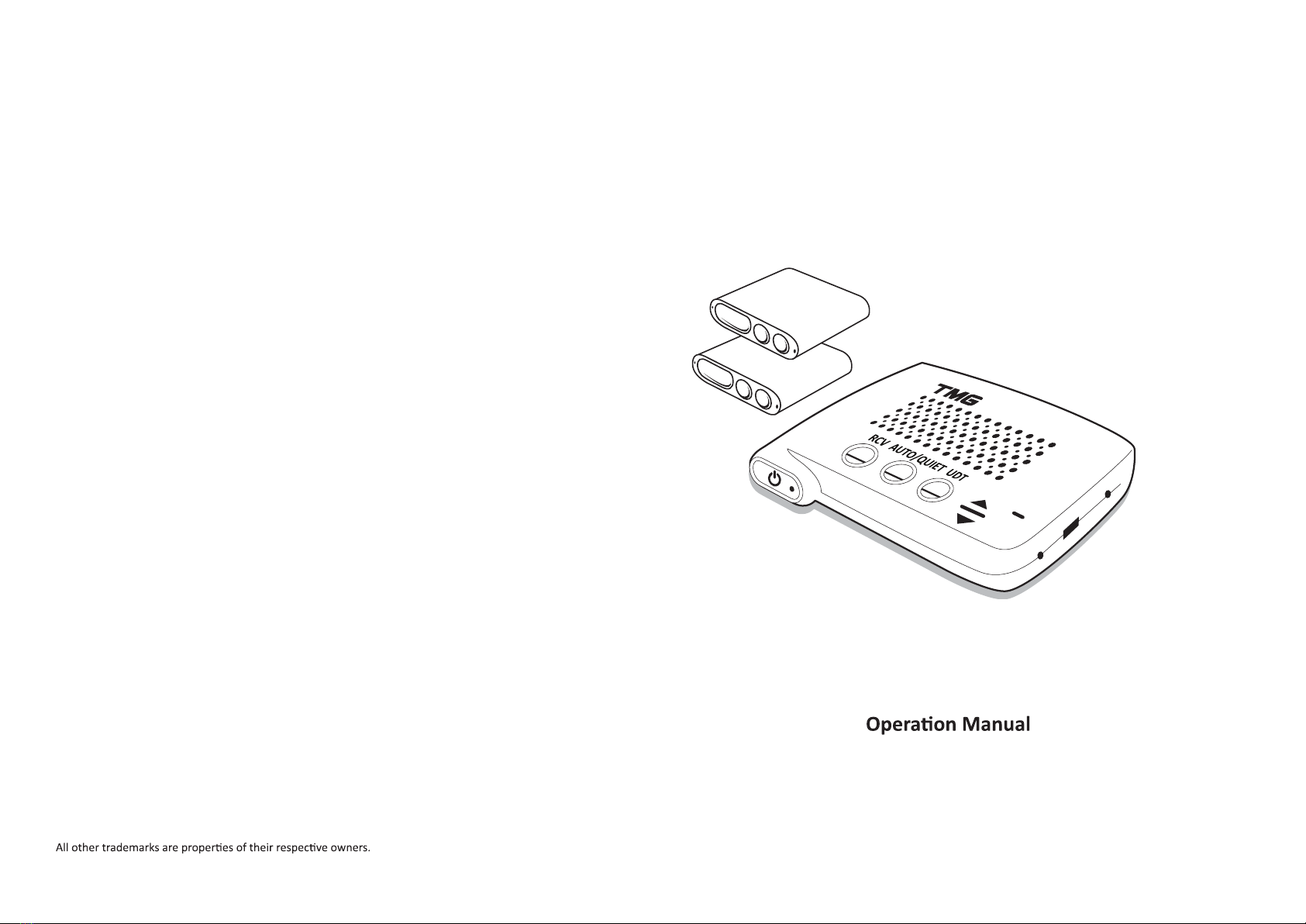
Please be sure to read this manual to familiarize yourself with the features and
TMG system is a class 1M laser product. Never look at the heads
closely while powered on! We recommend wearing Laser protected
Check your State and local laws on usage. We encourage you to disable your
and could result in suspicion that a LIDAR operator has been jammed. Auto-sleep
mode is default, and highly recommended with an Auto-kill feature to “Receive only
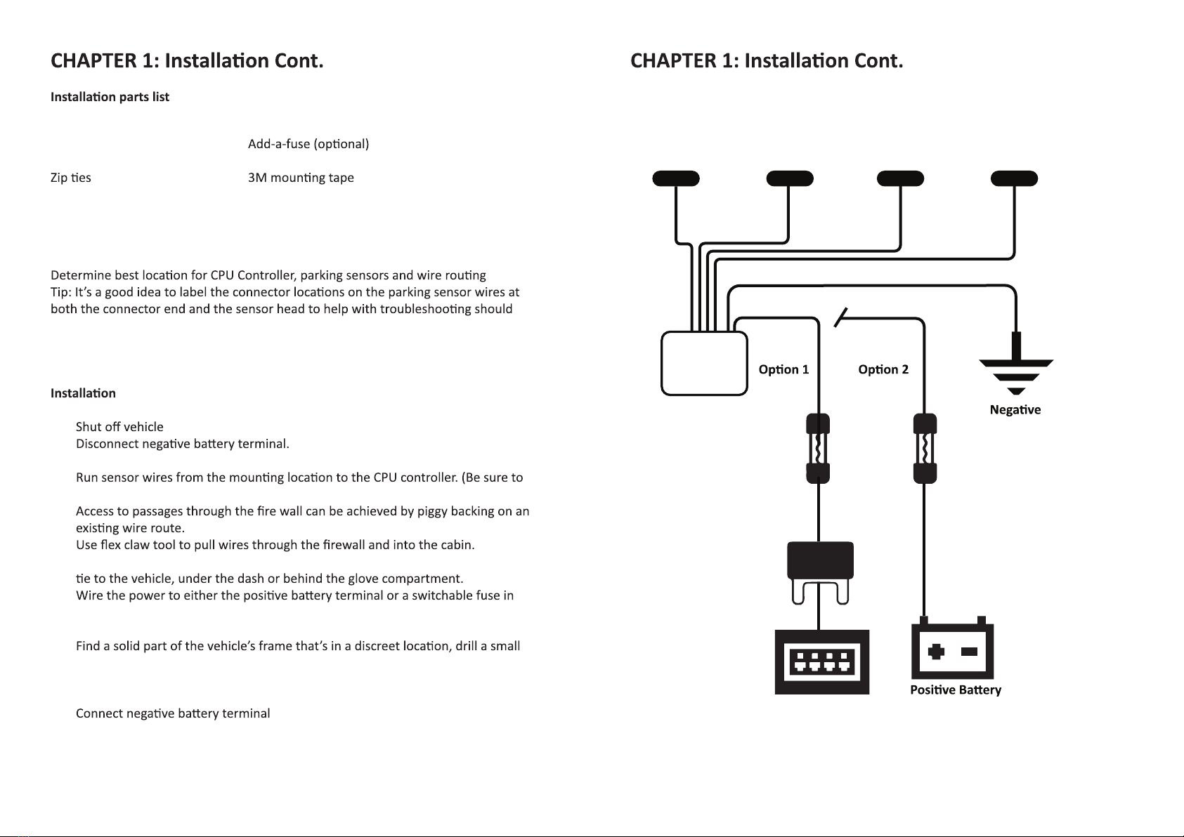
CPU only takes 12V power sources; A 24V power source will
damage the product permanently, and will void your 2 year
warranty.
Input ............................................................................... DC 12V
Laser Wavelength ........................................................... 905nm
.......................................................... Up to 75 W
..............................................................
.................................................. -10°F~150°F / -25°C~70°C
FCC ID ............................................................................. 2ARGWTMGA15
Fuse size ......................................................................... 2A 250V Glass
0.2 x 0.78 inch /
5 x 20 mm (2amp) (F2A)
Tool Requirements
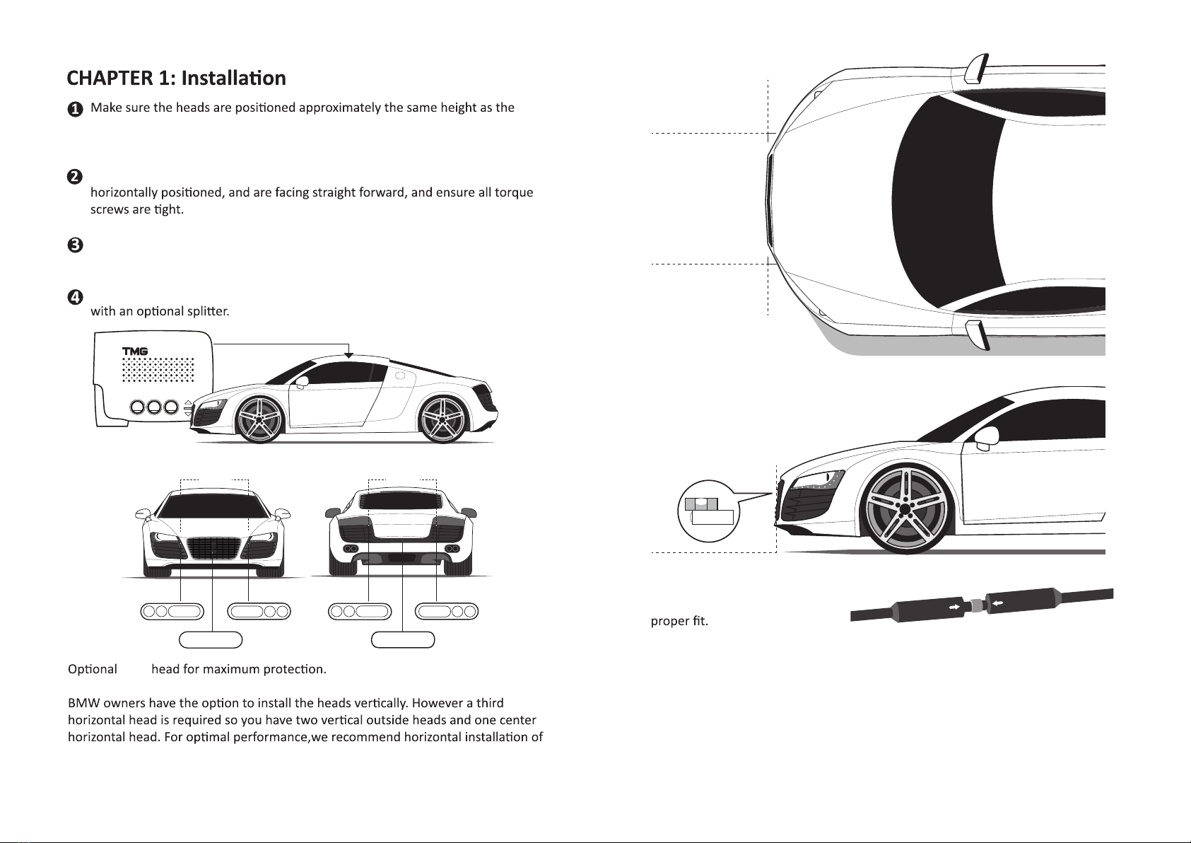
•T-10 torque bit or allen wrench
•Cordless screw driver- mount the brackets
•Small screws- to mount the brackets
•Velcro or 3m tape to mount the CPU
•
•Electrical tape - wrap up the head connectors and the wire to feed through
•Metal wire to feed the
wires through the
2 3
Indent
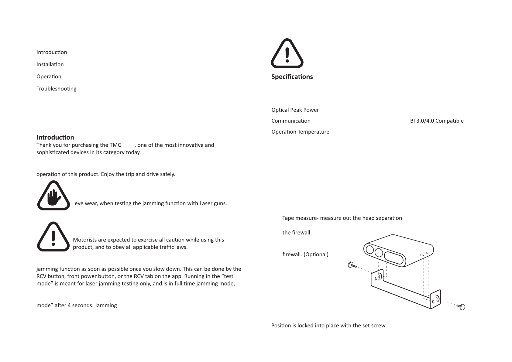
Set Screw
Detent
Coupler
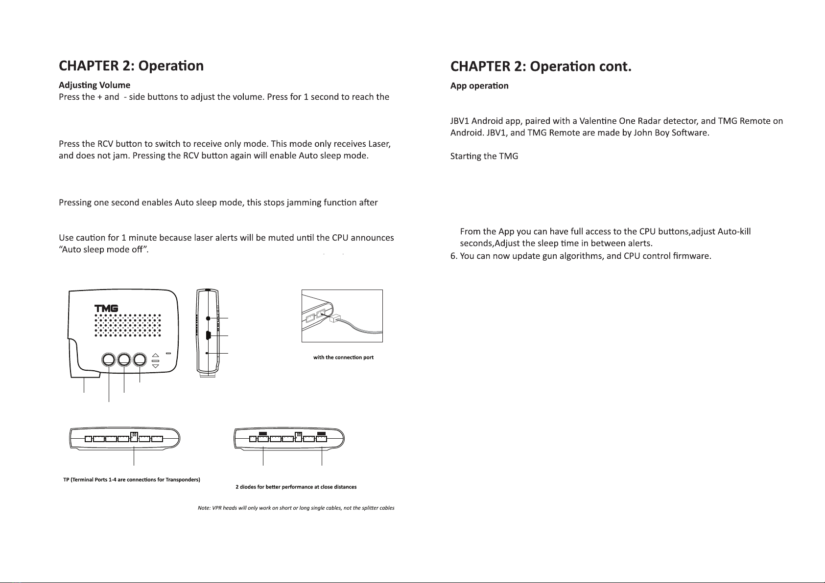
Detent on transponder lines up with indent on the bracket.
A-17
length can be adjusted through the App.